AERI-I-176-BK01混合动力车VSIM仿真参数输入表
CRUISE-电动车整车仿真输入参数

齿轮传动比表
传动比
变速器(AMT)
输入处齿数 输出处齿数
各档位传动比
各档位效率
主减速器(Final Drive)速效比率
差速锁
转矩分配因子
输入转动惯量
差速器(Differential) 输出转动惯量1
差速器(Differential)
输出转动惯量2
固定效率 静态滚动半径
车轮(Tire)
动态滚动半径
gear ratio table
transmission ratio number of teeth input number of teeth output
Transmission Ratio Efficiency Differential lock
Torque split factor Inertia moment in(kg* m2) inertia moment out 1(kg* m2)
Inertial moment(kg* m2)
inertia moment in(kg* m2) inertia moment out(kg* m2) maximum transferable torque(Nm pressure force brake piston surface specific brake factor Effective friction radius(mm)
drag coefficient Nominal Voltage Maximum Speed Torque-Speed Speed-Torque-Efficiency mass Initial Temperature
Maximum Mharge Initial Charge Nominal Voltage Maximum Voltage Minimum Voltage Number of cell Number of Cells per Cell-Row Number of Cell-Rows Operating Temperature Idle Voltage-Charge Idle Voltage-Discharge Ohimic Resistance-Charge Ohimic Resistance-Discharge
ELC-MC01 动力控制单元说明书

5011641701-MC012007-05-08ELC-MC01Motion Control UnitInstruction Sheet1WARNING•This Instruction Sheet only provides descriptions for installation, wiring and trial run. For furtherinfromation, please refer to special module of ELC Application Manual.•Do NOT touch terminals when power on. Please must power OFF before wiring.•This is an OPEN TYPE ELC. The ELC should be kept in an enclosure away from airborne dust, humidity,electric shock risk and vibration. Also, it is equipped with protective methods such as some special toolsor keys to open the enclosure in order to prevent hazard to users or damage the ELC.•Do NOT connect the AC input power to any of the input/output terminals, or it may damage the ELC.Check all the wiring prior to power up.•Warning – Do not disconnect while circuit is live unless area is known to be non-hazardous.•Power, input and output (I/O) wiring must be in accordance with Class 1, Div. 2 wiring methods - Article501-10(B)(1) of the National Electrical Code.•Suitable for use in Class 1, Division 2, Groups A, B, C, D or Non-Hazardous locations only.•Warning – Explosion hazard - Substitution of components may impair suitability for Class 1, Division 2.•Warning – Explosion hazard - Do not disconnect equipment unless power has been switched off or thearea is known to be Non-Hazardous.2 INTRODUCTION2.1 Model Description and PeripheralsMC01 (positioning unit) is mainly applied to the speed/position control of step/servo driven system. Themaximum output pulse can be up to 200 KPPS, and built-in various route control modes. The EATON ELCPB/PC/PH/PA series can read/write MC01 via FROM/TO instrucitons. There are 49 CRs (Control Register) with16-bit for each register in MC01. The 32-bits data is composed of 2 continuous CR number.2.2 Product Profile and Outline (LED Indicator and Terminal Block)Unit: mm1. Status Indicator (Power, L.V. and ERROR)2. Model name Upper Row Lower Row3. DIN rail clip4. Terminal S/S A-5. Terminal layout6. Mounting hole START B+7. Nameplate 8. Extension port to connect extension module STOP B-9. Extension unit/module clip 10. DIN rail track (35mm) DOG CLR+11. RS-485 communication port 12. Clip for combining extension modules LSP CLR-13. Power input 14. Extension port to connect extension module LSN FP+15. Upper row terminals 16. Lower row terminals PG0+ FP-PG0-RP+A+RP-2.3 LEDDisplayPOWER : Power indicator, +5V internal power START : Start inputLV : Low voltage indicator STOP : Stop inputlit when external input power is lower than 19.5V DOG : DOG (near point signal) inputERROR : Error indicator (ON/OFF blinking). FP : CW pulse outputIt will blink when CR#39 is not 0. RP : CCW pulse outputLSP : Right limit input indicator ΦA : A-phase input of manual pulse generatorLSN : Left limit input indicator ΦB : B-phase input of manual pulse generatorPG0 : Zero signal input indicator CLR : Output clear signal2.4 Input/OutputTerminalDescription Terminal name Content ResponsePower supply +24V, 0VPower input/DC24V (-15~+20%)±Current consumption 7010mA; Startup peak current 1.3 A-InputSTART Start input terminal 4ms/12msSTOP Stop input terminal 4msLSP / LSN Limit Stroke of right/left limit 1msΦA+, ΦA- A-phase terminal (+, -) of manual pulse generator input (line driver input) 200KHzΦB+, ΦB- B-phase terminal (+, -) of manual pulse generator input (line driver input) 200KHzPG0+, PG0- Zero signal input terminal +, - (line driver input) 4msInputDOGOffers two different functions depending on operation mode.(1) It is near-point signal in zero return mode.(2) It is start signal on interrupt 1st or interrupt 2nd speed mode.1msS/S Signal common terminal of these Inputs (START, STOP, DOG, LSP, LSN) -OutputCLR+, CLR- Clear signal (clear signal of internal error counter for Servo drive) 4msFP+, FP-FP/RP mode: CW pulse outputI/O mode: Output pulseAB-phase mode: A-phase output200KHzRP+, RP-FP/RP mode: CCW pulse outputI/O mode: direction outputAB-phase mode: B-phase output200KHzInput/Output CircuitNote:1. Do NOT arrange the wiring of I/O signal wires or power supply in the same wiring duct.2. Make sure the terminals of power module and ELC-MC01 are properly grounded or connects to machinecover.3.3 SPECIFICATIONS3.1 FunctionSpecificationsItem ContentPower supplyDC24V(-15% ~ +20%)Current consumption 70±10mA; Startup peak current 1.3 AMax. number ofconnected axes8 units; (PB/PC/PA/PH series MPU can connect up to 8 extension modules without occupying any I/O.)Distance instructionDistance value is set by CR.1. Setting range: -2, 147,483,648~+2,147,483,647;2. Selectable unit: um, mdeg, 10-4 inch, Pulse3. Selectable rate: 100, 101, 102, 103;4. Selectable position: absolute and relative position instructionSpeed instructionSpeed value is set by CR.1. Setting range: -2,147,483,648~+2,147,483,647 (conversion value of 10~200KPPS pulse)2. Selectable unit: pulse/s, cm/min, 10deg/min, inch/minExternal outputPhoto coupler is for insulation and there are LED indications for all output/input signals.Outputs: FP and RP (line driver output 5V)Output: CLR is the type of NPN open collector transistor output (5~24VDC, less than 20mA)External inputPhoto coupler is for insulation and there are LED indications for all output/input signals.±Input point: START, STOP, LSP, LSN, DOG(contact or open collector transistor, 24VDC10%, 5±1mA)ΦΦInputs:A, B(line driver or open collector transistor, 5~24VDC, 6~15mA)Input: PG0 (line driver or open collector transistor, 5~24VDC, 6~15mA)Pulse output format Three selectable modes: Pulse/Dir, FP (CW)/RP (CCW), A/B (all modes are line driver output)Position program & datatransmissionCR data can be read/write via FROM/TO intruction of ELC MPU. The 32-bit data is composed of 2continuous CR number. The range of 16-bit CR is CR#0 ~ CR#48.Connect to EATON ELCseriesModules are numbered from 0~7 with 0 closet and 7 farthest to the MPU. Up to 8 modules can beconnected without occupying any digital I/O.3.2 OtherSpecificationEnvironmental specificationsOperation/Storage1. Operation: 0~55(Temperature), 50~95%(Humidity), pollution degree 2()℃℃℃℃2. Storage: -25~70(Temperature), 5~95%HumidityNoise ImmunityESD(IEC 61131-2, IEC 61000-4-2): 8KV Air DischargeEFT(IEC 61131-2, IEC 61000-4-4): Power Line: 2KV, Digital I/O: 1KV, Analog & Communication I/O: 1KVRS(IEC 61131-2, IEC 61000-4-3): 26MHz~1GHz, 10V/mGroundingThe diameter of the grounding wire cannot be smaller than that of terminals 24V and 0V (if numerousELCs are used at the same time, make sure that each ELC is grounded respectively to the groundpoles)Agency ApprovalsUL508UL1604, Class1,Div2 Operating temperature code: T5European community EMC Directive 89/336/EEC and Low Voltage Directive 73/23/EECVibration/ShockimmunityStandard: IEC61131-2, IEC 68-2-6 (TEST Fc)/ IEC61131-2 & IEC 68-2-27 (TEST Ea)4 CR (Control Register)ELC-MC01 Motion control UnitCR No.Content Setting RangeHW LW AddressLatchedAttribute#0H’4190 O R Model No. System setting, Read-only (The model number of ELC-MC01 is H’0110.)#2 #1H’4191 O R/W Pulse rate (A)Range: 1 ~ +2,147,483,647 PPS/REV, factory setting: 2,000Pulse/Revolution (PLS/REV)#4 #3H’4193 O R/W Feed rate (B)Range: 1 ~ +2,147,483,647 unit/REV,Factory setting: 1,000 (unit*1/REV)#5H’4195 O R/WParameter settingFactory setting:H’0000b15 b14 b13b12b11b10b9 b8 b7b6 b5b4b3b2b1b0STOPinputpolaritySTARTinputpolaritySTARTresponsetimeAccelerationcurveoptionsDOGpolarityDOGtriggertimePulsedirectionZeroreturndirectionLSNinputpolarityLSPinputpolarityPulseoutputformatPositionratesettingUnitsettingb1 b0UnitMotorunitCombinedunitMachineunitb3b2Position rate setting b5b4Pulse output format0 0 MotorPosition pulse um 01000 0 FP + RP0 1 Machine pulse mdeg 0 1 1010 1 Pulse + direction1 0Combinedpulse 10-4inch 10 102 1A/B Phase pulse1 1Speedpulse/sec cm/min11 103 11pulse/sec 10deg/minpulse/sec inch/minbit # Content6When b[6]=0: positive logic. LSP input signal is ON and LPS signal is given.When b[6]=1: negative logic. LSP input signal is OFF and LPS signal is given.7When b[7]=0: positive logic. LSN input signal is ON and LSN signal is given.When b[7]=1: negative logic. LSN input signal is OFF and LSN signal is given.8When b[8]=0: zero return is executed to the direction of CP’s decreasing value. When b[8]=1, zero return is executed to thedirection of CP’s increasing value.9 When CW running is executed, b[9]=0 is for increasing CP value, but [9]=1 for decreasing.10When b[10]=0: DOG rising-edge is triggered. When b[10]=1,DOG falling-edge is triggered. (available for Interrupt 1st andinterrupt 2nd speed position modes)11When b[11]=0: positive logic. When DOG input signal is ON, DOG near point signal is given.When b[11]=1: negative logic. When DOG input signal is OFF, DOG near point signal is given.12 When b[12]=0: trapezoid acceleration line is chosen. When b[12]=1, S acceleration line is chosen.13 When b[13]=0: 4ms; when b[13]=1: 12ms(for noise filter).14When b[14]=0: positive logic. When START input signal is ON, START input.When b[14]=1: negative logic When START input signal is OFF, START input.15When b[15]=0: positive logic. When STOP input signal is ON, STOP input.When b[15]=1: negative logic. When STOP input signal is OFF, STOP input.#7#6H’4196 O R/W Maximum speed V max Range: 0 ~ +2,147,483,647 unit*1 (10 ~ 200K PPS) *2Factory setting: 200,000 unit*1#9#8H’4198 O R/W Bias speed V bias Range: 0 ~ +2,147,483,647 unit*1 (0 ~ 200K PPS pulse transfer value) *2Factory setting: 0 unit*1#11#10H’419A O R/W JOG speed V JOG Range: 0 ~ +2,147,483,647 unit*1 (10 ~ 200K PPS pulse transfer value) *2Factory setting: 5,000 unit*1#13#12H’419C O R/W Zero return speedV RTRange: 0 ~ +2,147,483,647 unit*1 (10 ~ 200K PPS pulse transfer value) *2Factory setting: 50,000 unit*1#15#14H’419E O R/WZero returndeceleration speedV CRRange: 0 ~ +2,147,483,647 unit*1 (10 ~ 200K PPS pulse transfer value) *2Factory setting: 1,000 unit*1#16H’41A0 O R/W The number of PG0in zero return mode NRange: 0~+32,767 PLSFactory setting: 0 PLS#17H’41A1O R/W The number of pulsein zero return mode PRange: -32,768 ~+32,767 PLSFactory setting: 0 PLS#18H’41A2O R/W Zero return modeH Modeb0: Zero return mode, b1: detect DOG falling-edge in zero return modebit #Content0 b[0]=0: normal mode, b[0]=1: override mode1 b[1]=0: DOG falling-edge detecting is on in zero return mode. b[1]=1: DOG falling-edge detecting is off in zero return mode.#20#19H’41A3 O R/W Zero point setting (HP) Range: 0 ~ ±999,999 unit*1; factory setting: 0 unit*1#21H’41A5 O R/W Acceleration time T acc Range: 10 ~ +32,767 ms; factory setting: 100 ms#22H’41A6 O R/W Deceleration time T dec Range: 10 ~ +32,767 ms; factory setting: 100 ms#24#23H’41A7 X R/W Target position (I) P(I)Range: -2,147,483,648 ~ +2,147,483,647 unit*1 (-2,147,483,648 ~+2,147,483,647 pulse transfer value) *2; factory setting: 0 unit*1#26#25H’41A9 X R/W Running speed (I) V(I)Range: -2,147,483,648 ~ +2,147,483,647 unit*1 (10 ~ 200K PPS pulsetransfer value) *2; factory setting: 1,000 unit*1#28#27H’41AB X R/W Target position (II)P(II)Range: -2,147,483,648 ~ +2,147,483,647 unit*1 (-2,147,483,648 ~+2,147,483,647 pulse transfer value) *2, factory setting: 0 unit*1#30#29H’41AD X R/W Running speed (II) V(II)Range: 0 ~ +2,147,483,647 unit*1 (10 ~ 200K PPS pulse transfer value)*2, factory setting: 2,000 unit*1.The ELC can be secured to a cabinet by using the DIN rail that is 35mm high with a depth of 7.5mm. When mounting the ELC on the DIN rail, be sure to use the end bracket to stop any side-to-side motion of the ELC, thus to reduce the chance of the wires being pulled loose. At the bottom of the ELC is a small retaining clip. To secure the ELC to the DIN rail, place it onto the rail and gently push up the clip.Notes:1. Please use 22-16AWG (1.5mm) wiring (either single or multiple core) for I/O wiring terminals.The specification for the terminals is as shown on the left. ELC terminal screws should betightened to 1.95 kg-cm (1.7 lb-in). Use Copper Conductor Only, 60/75 °C.2. I/O signal wires or power supply should not run through the same multi-wire cable orconduit.#31 H’41AF X R/WRunning instructionfactory setting: H’0000b15 b14 b13 b12 b11 b10 b9 b8 b7 b6 b5 b4 b3 b2b1 b0--CLRoutput(On/Off)CLRsignaloutputmode-Currentposition=-SoftwareSTARTABS/RELCoordinateZeroreturnstartJOG-JOG+CCWpulseSTOPCWpulseSTOPSoftwareSTOPErrorresetbit # Content Action7 When b[7]=0, it is absolute position. When b[7]=1, it is relative position. 0/18 Whenb[8]=01, start running by the work mode of CR#32.→0t110 Whenb[10]=01, current position (CP) is cleared to 0.→0t112When b[12]=0, CLR outputs 130ms to Servo when zero return is completed. It is the clear signal for servointernal error counter.When b[12]=1, CLR is common output point and the status(On/Off) is controlled by b[13].0/113 When b[13]=0, CLR output is Off. When b[13]=1, CLR output is On. 0/1#32 H’41B0 ╳R/WWork modeFactory setting:H’0001b15 b14 b13 b12 b11~b9 b8 b7 b6 b5 b4 b3 b2 b1b0--Currentposition:CR34,33;currentspeed:CR36,35;displayunit:Æpulse,1ÆunitReturntofactorysettingMASKsettingLSP/LSNstopmodeManualpulsegeneratorrangelimitationSTOPmodeManualpulsegeneratorinputoperationVariablespeedoperationmodestartInterrupt2nd-speedpositionmodestart2nd-speedpositionmodestartInterrupt1st-speedpositionmodestart1st-speedpositionmodestart5 When b[5]= 01, manual pulse generator input is started. Please refer to the setting of CR#40~#46.→6b[6]=0: When STOP is input, motor will decelerate to stop under running mode. When rerun instruction is received, motorwill neglect the uncompleted distance and directly go executing the next position instruction.b[6]=1: When STOP is input, motor will decelerate to stop under running mode. When rerun instruction is received, motorwill keep executing the uncompleted distance of previous instruction and then execute next position instruction.7b[7]=0: The output pulse of manual pulse generator is unlimited.b[7]=1: The output pulse of manual pulse generator is limited between P(I) and P(II). When the output pulse is out of therange, it will decelerate and then stop outputting.8b[8]=0: When motor is running, it will decelerate to stop if LSP/LSN signal is received.b[8]=1: When motor is running, it will stop immediately if LSP/LSN signal is received.9~11MASK setting (1st-speed operation, 2nd-speed operation, interrupt 1st-speed operation, interrupt2nd-speed operation)b[11~9]=K0(000) or other value: NO MASK function.b[11~9]=K1(001) : the rising-edge of input terminal A±will trigger MASK.ΦΦΦΦb[11~9]=K2(010) : the falling-edge of input terminal A±will trigger MASK.b[11~9]=K3(011) : the rising-edge of input terminal B±will trigger MASK.b[11~9]=K4(100) : the falling-edge of input terminal B±will trigger MASK.12 b[12]=1: All parameters return to factory setting.13b[13]=0: current position (CR34, 33) and current speed (CR36, 35). Display unit: pulse.b[13]=1: current position (CR34, 33) and current speed (CR36, 35). Display unit: unit.#34 #33 H’41B1 X R/WCurrent position CP(PLS)Range display: -2,147,483,648~+2,147,483,647 PLSFactory setting: 0 PLS#36 #35 H’41B3 X R/WCurrent speed CS(PPS)Range display: 0 ~ +2,147,483,647 PPSFactory setting: 0 PPS#37H’41B5X R/WCommunicationaddress and Baud ratesettingRS-485 communication address setting: setting range 01~225; factorysetting K1.Baud rate setting: 4800, 9600,19200, 38400, 57600, and 115200 bps.ASCII mode data format is 7Bit, even bit and 1 stop bit (7 E 1). RTU modedata format is 8Bit, even bit and 1 stop bit (8, E, 1)b0: 4800 bps(bit/sec.), b1: 9600 bps(bit/sec.) (factory setting)b2: 19200 bps(bit/sec.), b3: 38400 bps(bit/sec.)b 4: 57600 bps(bit/sec.), b 5: 115200 bps(bit/sec.)b6: reserved, b7: 0 for RTU, 1 for ASCII mode,b8~b15: communication address#38 H’41B6 O R/WExecution statusfactory setting:H’XXXXb15b14b13b12b11b10b9b8b7b6b5b4b3b2b1b0-----MPGinputdownwardMPGinputupward-RoutepausedindicationPositioncompletedindicationErroroccurredflagCPvalueoverflowZeroreturnisdoneCCWpulseisoutputtingCWpulseisoutputtingStatusindicationbit # Content0 When b[0]=0, system is ready. When b[0]=1, MC01 is executing position control mode (Pulse is outputting).1 When b[1]=1, CW pulse is outputting.2 When b[2]=1, CCW pulse is outputting.3When b[3]=1, zero return is completed and b[3] will be cleared by user-defined program. When MC01 is power on again, b[3]will be cleared to 0 automatically.4When b[4]=1, “Current position CP(PLS)”(CR#34, #33) of 32 bit will overflow. When MC01 is power on again or complete zeroreturn, b[4] will be cleared to 0 automatically.5 When b[5]=1, MC01 error occurred. Error code is stored in CR#39.6When MC01 starts executing zero return or error reset (only when error occurred), it will clear b[6] to 0. When zero return orposition control is completed, it will set b[6] to 1.7When MC01 is running and STOP status is on, MC01 will stop output and b[7] will be set to 1. It means that MC01 is pausedand it will execute the uncompleted route and b[7] will be cleared to 0 after STOP status is off.9 When b[9]=1, it means manual pulse generator inputs with counting upward.10 When b[10]=1, it means manual pulse generator inputs with counting downward.#39H’41B7 X R ErrorcodePlease refer to “Error Code & Troubleshooting” for detail. Factory setting:H’0000#40H’41B8 X R/WElectronic gearingnumerator of MPGinputPlease refer to the following explanationFactory setting: H’1#41H’41B9 X R/WElectronic gearingdenominator of MPGinputPlease refer to the following explanationFactory setting: H’1*1: Unit setting varies based on b0 and b1 setting of CR#5.*2: Use max. pulse output if upper limit is exceeded. Use min. pulse output if lower limit is exceeded.z CR#0~CR48: user can use the corresponding addresses H4190~41C0 to read/write data via RS-485 communication.1. Baud rate supportive: 4,800, 9,600, 38,400, 57,600, and 115,200 bps.2. Modbus ASCII/RTU: ASCII mode is 7Bit, even bit and 1 stop bit (7,E,1). RTU mode is 8Bit, even bit and 1 stop bit (8, E, 1).3. Function code: 03H for read data from CR; 06H for write one WORD in CR; 10H for write many WORDs in CR.5 INSTALLATION & WIRINGTo remove it, pull down the retaining clip and gently pull the ELC away from theDIN rail. As shown on the right:When installing the ELC, make sure that it is installed in an enclosure withsufficient space (as shown on the right) to its surroundings so as to allow heatdissipation.1. Installation of the DIN rail2. Wiring。
混合动力汽车动力系统的仿真与设计
混合动力汽车动力系统的仿真与设计【摘要】本文介绍了混合动力汽车动力系统的基本设计方法,根据设计的性能要求对动力系统参数进行了设计,用电动汽车仿真软件ADVISOR对整车性能进行了仿真计算,验证了参数设计的合理性。
【关键词】混合动力汽车;动力系统;仿真;设计一、前言新能源汽车的发展是我国汽车行业的战略性发展方向。
在新能源汽车中,混合动力汽车继承了石油燃料高比能量和高比功率的优点,弥补了纯电动汽车续驶里程短的不足,使其成为当前新能源汽车领域最为切实可行的方案[1]。
混合动力汽车设计的过程中,动力系统的参数设计是其关键部分,本文针对动力系统相关参数的设计与计算,讨论了混合动力汽车动力系统参数设计的一般思路和方法。
二、混合动力汽车动力系统参数设计1.发动机参数设计发动机是混合动力汽车的主要动力来源,因此,发动机的参数选择是整个动力系统参数设计的重要部分。
对发动机参数的设计主要工作是对发动机功率的选择。
如果发动机功率选择过大,汽车的燃油消耗就会严重,经济性能差;如果发动机功率选择较小,后备功率就小,动力性能不足。
发动机功率的选择是由汽车在单驱动工况下行驶的最大速度及其爬坡度来决定的,即:其中,Pemax为发动机最大功率;为传动系效率;为最高车速;m为汽车的总质量;为滚动阻力系数;为空气密度;CD为空气阻力系数;A为迎风面积。
由于混合动力汽车发动机提供的是汽车正常行驶时的平均功率,因此,发动机功率的选择主要是根据汽车匀速行驶的工况下功率的值,使发动机工作在经济性能最好的区域,用下式计算:其中,Pe为汽车正常行驶时的功率;为汽车的平均行驶速度。
2.电机参数设计混合动力汽车使用的电机具有这样的特性:电机以小于额定转速工作时,处于恒定转矩的工作模式,反之,处于恒定功率的工作模式。
电机本身的质量、尺寸、损耗等因素都直接影响着最高转速,对传动系尺寸的大小也有较大的影响。
电机的最高转速与额定转速的比值,称为电机扩大恒功率区系数β。
普锐斯混合动力汽车建模与仿真分析_尹攀飞
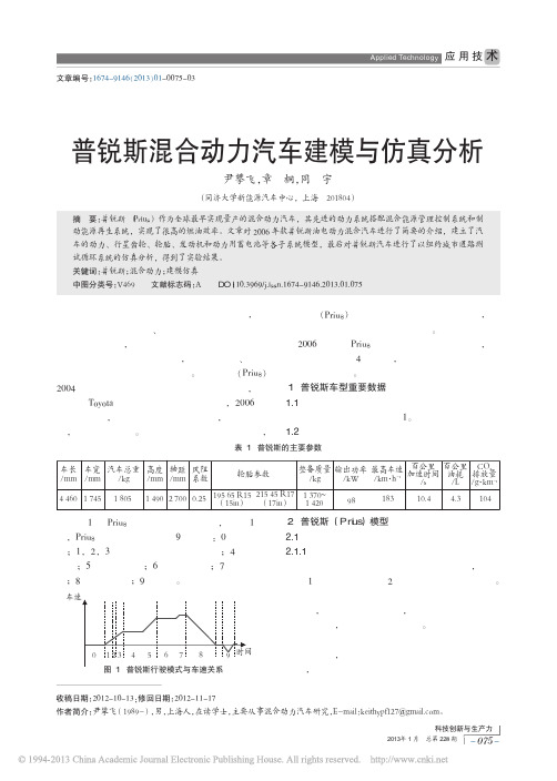
48 km/h 为 1.5 kW, 80 km/h 为 6.4 kW, 125 km/h 为
20.2 kW。
2.1.3 轮胎力学模型
SimDriveline 中 的 轮 胎 模 型 分 别 采 用 的 是 著 名
的 “Magic Formula” 轮胎模型。 轮胎纵向动力为
Fx = Fz〔Dsin{Carctan[B·x-
Vb
=
E0
-
R·i
-
K
Q
Q - it
it + i* + Aexp -B·it , (13)
其 中 , Vb 为 电 池 电 压 , E0 为 电 池 恒 定 电 压 , R 为 内阻, i 为电流, K 为极化电阻极化常数, Q 为电
池 容 量 , K Q 为 极 化 电 阻 , K Q it 为 极 化
50
00 1 000 2 000 3 000 4 000 5 000 6 000 转速 /r·min-1
图 3 电动机效率检索表
d dt
id
=
1 Ld
vd -
R Ld
id +
Lq Ld
pωriq;
(10)
d dt
iq =
1 Lq
vq -
R Lq
iq -
Lq Lq
pωrid -
λpωr Lq
;
(11)
Q - it
Q - it
电 压 , i* 滤 波 后 电 流 , A 为 指 数 区 振 幅 , exp (t)
乙 为指数区电压, it= idt 为电池实际充电量。
3 结论 混合动力汽车零部件的合理匹配对提高发动机
经济性和排放性能具有重要的作用。 通过上述分 析, 笔者对混合动力车进行了纽约城市行驶工况仿 真测试(见图 4), 采用车载排放测试系统, 模拟了 汽车在城市道路中行驶并频繁启停的工作状况, 并
基于Simulink的混合动力车型动力经济性仿真模型

项目 整车整备质量,kg
风阻系数 迎风面积,m2 车轮滚动半径,m 发动机转速范围,rpm TM电机最高转速,rpm ISG电机最高转速,rpm 发动机转动惯量,kg·m2 车轮转动惯量,kg·m2 电机及其他齿轮转动惯量,kg·m2 地面附着系数 电池总容量,kWh
电池电压,V 电池内阻,Ω 能量回收车速范围,km/h
考核项目试验载荷整车阻力设定备注参考标准动力性最高车速hev1km最高车速道路kmhcw1875物理参数混合动力车型适用gbt197522005gbt197502005gbt326942016gbt183852005gbt183882005gbt283822012等ev1km最高车速道路kmhcw1875物理参数新能源车型适用发动机巡航最高车速kmhcw1875物理参数hev30min最高车速cw1875物理参数混合动力车型适用ev最大爬坡车速4121kmkmhcw375物理参数新能源车型适用hev最大爬坡车速4121kmkmhcw375物理参数混合动力车型适用加速性能hev0100kmh加速时间scw1875物理参数混合动力车型适用hev0400m加速时间scw1875物理参数混合动力车型适用hev60100kmh加速时间scw1875物理参数混合动力车型适用hev80120kmh加速时间scw1875物理参数混合动力车型适用ev050kmh加速时间scw1875物理参数新能源车型适用ev5080kmh加速时间scw1875物理参数新能源车型适用ev0100kmh加速时间scw1875物理参数新能源车型适用爬坡能力hev最大起步坡度cw375物理参数混合动力车型适用hev最大爬坡度cw375物理参数混合动力车型适用ev最大起步坡度cw375物理参数新能源车型适用ev最大爬坡度cw375物理参数新能源车型适用经济性条件anedc工况百公里能耗cw100滑行法混合动力车型适用gbt197532013gbt197502005gbt183862017等条件bnedc工况百公里能耗cw100滑行法包含发动机的车型适用nedc加权平均油耗l100kmcw100滑行法混合动力车型适用续驶里程ev工况纯电续驶里程kmcw100滑行法新能源车型适用概述行业内采用的动力经济性仿真手段有
某款纯电动汽车动力匹配与仿真

FOCUS 技术聚焦设计•创新摘要:为了实现某款电动汽车的动力匹配,利用M ATLAB 软件计算得出该纯电动汽车电机、变速器和蓄电池的相关参数。
以M ATLAB 和A D V ISO R 仿真软件为平台,以该款纯电动汽车为原型,编写相应的程序和数据输入到文档中,对纯电动汽 车的动力系统进行仿真分析。
仿真结果表明,该纯电动汽车匹配的动力系统能够满足动力性指标和续驶里程的要求,符合相 关技术要求。
关键词:纯电动汽车;MATLAB; ADVISOR ;参数匹配;仿真Parameter Matching and Simulation of a Battery Electric Vehicle Power SystemAbstract : In order to carry out a certain electric power matching, using MATLAB software to calculate the related parametersof electric motor, transmission and battery is introduced in this paper. Taking this battery electric vehicle as the prototype, using MATLAB and ADVISOR software to write the corresponding program and data and input to the document, the battery electric vehicle power system is simulated. The simulation results show that the dynamic system of the battery electric vehicle can meet the dynamic requirements, the driving range and meet the relevant technical specifications.Key words : Battery electric vehicle; MATLAB ;ADVISOR;Parameter matching; Simulation随着环境污染和能源紧缺的加重,传统燃油汽车 产业面临着巨大的挑战,新能源汽车自然成为汽车研 究的热点,如今电动汽车已成为汽车产业发展的主要 研究方向之一[1-]。
能源控制器Ⅰ型使用说明书

能源控制器Ⅰ型使用说明书青岛东软载波科技股份有限公司能源控制器类型标识代码分类说明NC X X X X-XXXX 能源控制器场景远程通信本地通信总线通信产品代号NC-能源控制器1-公变2-专变1-4G2-5G0-无1-HPLC2-微功率无线3-双模1-RS-4852-M-bus3-CAN由不大于8位的英文字母和数字组成。
英文字母可由生产企业名称拼音简称表示,数字代表产品设计序号能源控制器的功能模块类型标识代码分类见下表。
功能模块类型标识代码分类说明G X X X X-XXXX功能模块功能模块类型功能模块类型属性接口数量温度级别产品代号G-功能模块K-控制模块X-遥信模块B-本地通信模块Y-远程通信模块M-模拟量采集模块T-其他功能模块类型无补充属性,则为X;本地通信模块:Z-窄带电力线载波H-HPLCJ-微功率无线S-双模通信模块(载波&无线)M-MBUS通信模块R-RS485通信模块C-CAN通信模块T-其它信道远程通信模块:2-无线公网2G3-无线公网3G4-无线公网4G5-无线公网5GA-230MHz专网L-以太网有线网络N-公共交换电话网F-光纤有线网络T-其他信道多功能组合模块类型属性定义为:Z。
对外物理接口数量:1~9-1~9路物理接口1-C12-C23-C34-Cx由不大于8位的英文字母和数字组成,必须包含版本信息。
英文字母可由生产企业名称拼音简称表示,数字代表产品设计序号尊敬的用户:首先衷心感谢您选择青岛东软载波科技股份有限公司的产品。
青岛东软载波科技股份有限公司成立于1993年6月,2011年2月在创业板上市,现已形成以智能制造为基础,芯片设计为源头,能源互联网与智能化应用两翼齐飞的产业布局。
公司发展战略是以集成电路设计为基础,开展以融合通信为平台的技术研发;布局“芯片、软件(模组)、终端、系统、信息服务”产业链,聚焦能源互联网、智能化应用这两个战略新兴领域,打造国际一流企业。
发动机模拟器(EVS-I型发动机车辆信号仿真仪用户手册)
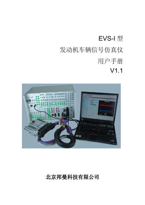
1.2 功能
本仿真仪的功能是仿真发动机 ECU 模块工作需要的发动机正时信号以及各 种传感器及开关信号。
本仿真仪模拟以下信号:
编号 信 号 名 称 型式 范 围 方向
备注
1 电源
电压 24V
输出 额定电流 32A(800W)
2 T15
电压 悬空|24V 输出
3 T50
电压 0|24V
输出
4 发动机转速
12 机油压力
电压 0-5V
输出
13 进气压力
电压 0-5V
输出
14 远程油门
电压 0-5V
输出
15 预留模拟通道 1 电压 0-5V
输出
16 EGR 前压力
电压 0-5V
输出
17 EGR 后压力
电压 0-5V
输出
18 DPF 压降
电压 0-5V
输出
1
EVS‐I 型发动机车辆信号仿真仪
19 预留模拟通道 2 电压 0-5V
北京邦曼科技有限公司
使用本仪器前请详细阅读本说明书,并妥善保存,以备将来参考之用。
1 前言
1.1 术语
本手册中使用的术语如下,在操作过程中的安全警告必须严格注意。
警告: 警告性声明指出可能会危害生命安全的条件和行
为。
注意: 注意性声明指出使用本产品中的一些辅助事项。
电压
输出 见软件帮助
5 车速
频率 0-0.5kHz 输出 0/12V 方波
6 风扇转速
频率 0-1.5kHz 输出 0/5V 方波
7 多态开关
电阻
输出 9.8/4.2/1.5kΩ
8 油门踏板
电压 0-5V
输出
9 油轨压力
- 1、下载文档前请自行甄别文档内容的完整性,平台不提供额外的编辑、内容补充、找答案等附加服务。
- 2、"仅部分预览"的文档,不可在线预览部分如存在完整性等问题,可反馈申请退款(可完整预览的文档不适用该条件!)。
- 3、如文档侵犯您的权益,请联系客服反馈,我们会尽快为您处理(人工客服工作时间:9:00-18:30)。
NEDC油耗(L/100km)
★
原型车P&E性能试验报告
★另附
混动车
性能
混动车P&E性能试验报告
★另附(第三、四轮仿真时提供)
整车技术部
原型车
重量参数
整备质量(kg)
★
满载质量(kg)
★
满载前后轴载荷比
★
发动机装置重量(kg)
★
进、排气系统重量(kg)
冷却系统(含冷却液)重量(kg)
中冷系统重量(kg)
燃油系统(含汽油)重量(kg)
混动车
重量参数
整备质量(kg)
★(目标设定值)
满载质量(kg)
★(目标设定值)
满载前后轴载荷比
★(目标设定值)
发动机装置重量(kg)
★
进、排气系统重量(kg)
冷却系统(含冷却液)重量(kg)
中冷系统重量(kg)
燃油系统(含汽油)重量(kg)
项目管理组
混动车
目标参数
最高车速(km/h)
其他要求:
换挡策略
另附
重量(kg)
★
主减
减速比
传动效率
混动车
发动机
型号
峰值扭矩(N·m)
★
最大功率(kW)
★
转动惯量(kg·m2)
★
重量(kg)
外特性数据
★另附
万有特性数据
★另附
变速器
型号
各挡减速比
★
各挡效率
★
最大输入扭矩(N·m)
★
换挡策略
★另附
重量(kg)
★
主减
减速比
★
传动效率
★
底盘
原型车IM仿真参数输入表
版本:V1.0
汽车工程研究院
节能环保部
2016年6月15日
主管部门
混合动力车VSIM仿真参数输入表V1.0
责任
工程师
会签
车型
类别
名称
参数
备注
动总
原型车
发动机
型号
峰值扭矩(N·m)
最大功率(kW)
转动惯量(kg·m2)
重量(kg)
★
变速器
型号
各挡总减速比
最大输入扭矩(N·m)
★(目标设定值)
最大爬坡度(%)
★(目标设定值)
0~100km/h加速时间(s)
★(目标设定值)
NEDC综合油耗(L/100km)
★(目标设定值)
配置要求
可另附
备注:标★项为必填项,第二轮仿真时若无真实数据,相关责任工程师可根据设计目标或对标参数或沿用原型车参数或经验预估值填写(标明参数来源),第三、四轮仿真时应填写真实数据。必填项参数不全,仿真分析工作无法有效开展。另附表格的格式参照研究院流程AERI-I-058《整车动力性经济性计算流程》附表格式。
滚动阻力系数
混动车
轮胎
型号
★
滚动半径(mm)
★
滚动阻力系数
★
CAE
原型车
风阻参数
迎风面积(m2)
空气阻力系数
混动车
风阻参数
迎风面积(m2)
★
空气阻力系数
★
试验部
原型车
性能
滑行阻力曲线/试验质量(kg)
★
最高车速(km/h)
★
最大爬坡度(%)
★
0~50km/h加速时间(s)
0~100km/h加速时间(s)