PM3350-RC中文资料
航模3505电机参数

航模3505电机参数全文共四篇示例,供读者参考第一篇示例:航模3505电机是一种常见的直流无刷电机,广泛应用于航模飞行器的动力系统。
它具有高效率、低噪音、稳定性好等特点,因此备受模型飞行爱好者的青睐。
下面我们将详细介绍航模3505电机的参数及其性能特点。
首先,我们来看一下航模3505电机的基本参数。
该电机的直径为35mm,长度为05mm,轴径为3mm,重量约为50克。
工作电压范围为2-4S锂电池,推荐使用3S电池,额定电压为11.1V。
电机的空载转速约为1500-12000转/分钟,最大功率可达150W,最大电流为15A,电机内阻为0.11Ω。
航模3505电机的性能特点主要包括以下几个方面:1.高效率:航模3505电机采用无刷电机设计,具有高效率和低能耗的特点。
在相同功率下,比传统有刷电机更省电,运行更稳定。
2.低噪音:由于航模3505电机采用了无刷电机技术,相对于有刷电机来说噪音更低,工作时几乎没有嗡嗡声,能够更好地保护用户的听力。
3.稳定性好:航模3505电机采用了高品质的材料和先进的生产工艺,具有出色的稳定性和耐用性。
在长时间高速运转也不易受损,寿命较长。
4.适配性强:电机的设计尺寸紧凑,重量轻,适用于多种航模飞行器,如固定翼飞机、直升机、四旋翼等,灵活方便。
5.易安装:航模3505电机安装简便,只需将电机与飞行控制器连接,加装适当的电调和螺旋桨即可投入使用。
对于初学者和DIY爱好者来说,是一个理想的选择。
总的来说,航模3505电机作为一种高性能、多功能的直流无刷电机,适用于各种模型飞行器的动力系统,具有较好的可靠性和稳定性,是模型飞行爱好者的首选之一。
希望以上介绍能够帮助大家更深入了解航模3505电机的参数及性能特点,选择适合自己的电机,享受飞行的乐趣。
第二篇示例:【航模3505电机参数】航模3505电机是一款性能稳定、品质可靠的无刷直流电机,广泛用于遥控模型飞机、无人机和车辆等领域。
本文将详细介绍航模3505电机的参数及特点。
三品变频器主要参数

Pr078 PLC 运转方向
参数值01001010换成十进制 即:01001010B=74 所以参数Pr078=74
Pr079
PLC加减速时间
Pr079=0000000001100011B=99
内控多段速(定时器)
Pr087 Pr088 Pr089 Pr090 Pr091 Pr092 Pr093 Pr094 定时器一 定时器二 定时器三 定时器四 定时器五 定时器六 定时器七 定时器八
运行时间由 Pr087~Pr094 定时器设定,不 用的控制段,定时器设定为零即可 各段速运行方向由 Pr078 (PLC 运转方向) 设定 各段速加减速时间由 Pr079(PLC 加减速时 间)设定
Pr003-Pr007用来确定变频器的V/F曲线, 以应对不同的负载特性
Pr009 频率下限
说明: 频率下限主要防止现场人员的误操作,避 免马达因运转频率过低可能产生的过热或 其他机械故障等。 频率下限的设定必须小 于频率上限的设定值。 (频率上限即Pr007最高操作频率) 类比施耐德变频器SEt-LSP、 SEt-HSP
三品变频器主要参数说明
Pr000
主频率设定
说明: 在运转频率来源设定为面板操作情况下, 频率以 Pr000 设定值运行。 在多段速运行中,主频率为第一段速频率。 在设定为外控多段速运行时,如果把Pr034 设定为1,即外部端子给定时,则第一段速 由外部端子模拟量给定。 主频率的设定受最大操作频率限制。
类比施耐德变频器SEt-JPF、JF2
多功能输入端子设置
三品:端子——功能 施耐德:功能——端子
多功能输出端子设置
输出配置:I-O-AOIt、dO(AOV/AOC) 继电器配置:I-O-r1、r2
日本三和PM3笔记本式万用表中文说明书
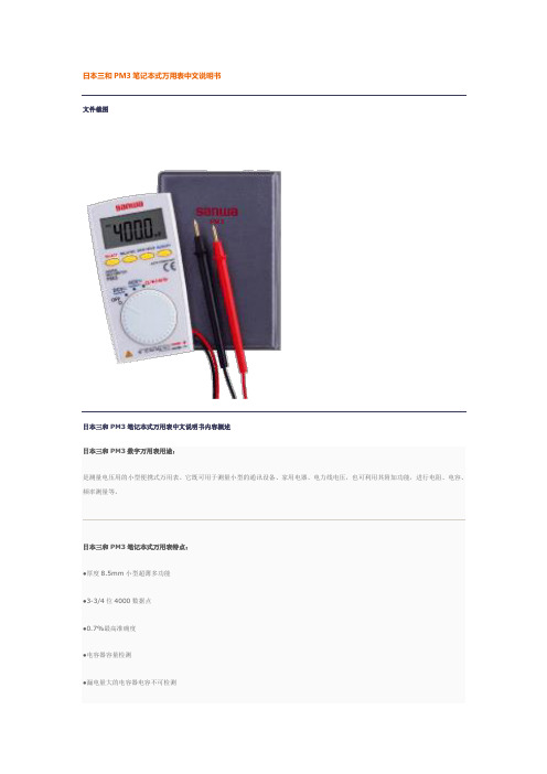
文件截图
日本三和PM3笔记本式万用表中文说明书内容概述
日本三和PM3数字万用表用途:
是测量电压用的小型便携式万用表。它既可用于测量小型的通讯设备、家用电器、电力线电压,也可利用其附加功能,进行电阻、电容、频率测量等。
日本三和PM3笔记本式万用表特点:
●厚度8.5mm小型超薄多功能
●背光及控制带LED的蜂鸣器
日本三和PM3笔记本式万用表特性:
●显示:数值4000
●抽样率:数值3次/秒
●安全规格:IEC1010 CAT. II DC/AC500V MAX.
日本三和PM3笔记本式万用表技术参数
PM3
测量量程
最高准确度
分辨率
输入电阻
直流电压
400m/4/40/400/500V
±(0.7%+3)
±(0.7%+5)
0.1Ω
占空比
0.1-99%
通断
10Ω-120Ω以下有蜂鸣音开路电压:约0.4V
二极管测试
开路电压约1.5V
频率特征
40-400HZ
内置电池
纽扣式锂电池C8*W56*D11.5mm/约85g
附件
手册型护套(C-PM3),使用说明书
0.1mv
DCV
10M-100MΩ
ACV
10M-11MΩ
交流电压
4/40/400/500V
±(2.3%+10)
0.001v
电阻
400/4K/40K/400K/4M/40MΩ
±(2.0%+5)
0.1Ω
电容器容量
4n/40n/400n/4μ/40μ/200μF
±(5.0%+10)
Cisco 350系列产品参数与价格表说明书
4800 Series Adapter
AIR-PC4800
DESCRIPTION
350 Series PC Card w/Integrated Diversity Antenna,128-bitWEP 350 Series PC Card Adapter w/128-bit WEP 40 Pack 350 Series PCI Adapter w/128-bit WEP 10 Pack 350 Series PCI Adapter w/RP-TNC,Dipole Antenna,128-bit WEP 350 Series PC Card w/Dual MMCX Connectors and 128-bit WEP 350 Series PC Card w/Dual MMCX and 128-bit WEP 40 Pack
350 Series Power
AIR-SSI350-J-K9 AIR-PWRINJ=
340 Series Access Point
AIR-BSE342
AIR-AP342E2C AIR-AP342E2R
340 Series Access Point Accessory AIR-ACC5559-072
350 Series Workgroup Bridge w/Captured Antenna / 128-bit WEP 350 Series Workgroup Bridge w/Dual RP-TNC and 128-bit WEP 350 Series 11Mbps, DSSS Bridge w/128-bit WEP 350 Series 11Mbps, DSSS Bridge w/128-bit WEP 350 Series 11Mbps, DSSS Bridge w/128-bit WEP 350 Series Site Survey Kit 350 Series Site Survey Kit 350 Series Site Survey Kit
panasonic RC-CD350 说明书

Model No.RC-CD350Operating instructionsCD Clock RadioDear customerThank you for purchasing this product.Before connecting, operating or adjusting this product, please read theseinstructions completely. Please keep this manual for future reference.Note“EB” on the packaging indicates the United Kingdom.Matsushita Electric Industrial Co., Ltd.Web Site: http://www.panasonic.co.jp/global/RQT7608-1BH0204ZZ1026EB GN En1 loop antenna: RSA0031Use the numbers indicated when asking for replacement parts.www. (for UK customers only)•Order accessory and consumable items for your product with ease andconfidence by telephoning our Customer Care Centre Mon-Friday 9:00am-5:30pm. (Excluding public holidays.)•Or go on line through our Internet Accessory ordering application.•Most major credit and debit cards accepted.•All enquiries transactions and distribution facilities are provided directly byPanasonic UK Ltd.•It couldn’t be simpler!Customer Care CentreForUKcustomers************For Republic of Ireland customers: 01 289 8333Technical SupportForUKcustomers************This Technical Support Hot Line number is for Panasonic PC softwarerelated products only.For Republic of Ireland, please use the Customer Care Centre number listedabove for all enquiries.For all other product related enquiries, please use the Customer CareCentre numbers listed above.Troubleshooting guideBefore requesting service, make the below checks. If you are in doubt about some ofthe check points, or if the remedies indicated in the chart do not solve the problem,consult your dealer for instructions.The clock shows “-:--”. •Set the clock.There is a lot ofnoise.•Keep away from mobile phones, televisions, and othertuners.•Extend and change the direction of the antenna.The alarm doesn’tsound at the set time.•Ensure the alarm’s indicator is on (“ALARM 1”, “ALARM2”, or “ALARM 3”).The memory hasbeen cleared.•Reset the items into the memory.•Insert a battery to preserve the memory contents.“no dISC” appears.•You haven’t inserted a CD.Play doesn’t start ordisplay is incorrect.•Clean the CD.•Clean the lens with a blower (SZZP1038Crecommended). If the lens gets marked withfingerprints, gently wipe them off with a cotton swab.•Wait an hour for condensation to dry, then try again.•Make sure the label is facing out.•Replace the CD if it is scratched, warped, or irregularlyshaped.The CD or radiodisplay disappears.•These displays disappear after a few seconds. To showthem again, press [DISPLAY, –DIMMER].For the United Kingdom and Republic of Ireland(Inside of product)(For United Kingdom)(“EB” area code model only)For your safety, please read the following text carefully.This appliance is supplied with a moulded three pin mains plug for your safety and convenience.A 5-ampere fuse is fitted in this plug.Should the fuse need to be replaced please ensure that the replacement fuse has a rating of 5-ampere and that it is approved by ASTA or BSI to BS1362.Check for the AST A markor the BSI markon the body of the fuse.If the plug contains a removable fuse cover you must ensure that it is refittedwhen the fuse is replaced.If you lose the fuse cover the plug must not be used until a replacementcover is obtained.A replacement fuse cover can be purchased from your local dealer.If a new plug is to be fitted please observe the wiring code as stated below.If in any doubt please consult a qualified electrician.IMPORTANTThe wires in this mains lead are coloured in accordance with the followingcode:Blue: Neutral, Brown: Live.As these colours may not correspond with the coloured markings identifyingthe terminals in your plug, proceed as follows:The wire which is coloured Blue must be connected to the terminal which ismarked with the letter N or coloured Black or Blue.The wire which is coloured Brown must be connected to the terminal whichis marked with the letter L or coloured Brown or Red.WARNING: DO NOT CONNECT EITHER WIRE TO THE EARTHSYMBOL OR COLOURED GREEN OR GREEN/YELLOW.THIS PLUG IS NOT WATERPROOF–KEEP DRY.Before useRemove the connector cover.How to replace the fuseThe location of the fuse differ according to the type of AC mains plug (figuresA and B). Confirm the AC mains plug fitted and follow the instructions below.Illustrations may differ from actual AC mains plug.1. Open the fuse cover with a screwdriver.CAUTION!THIS PRODUCT UTILIZES A LASER.USE OF CONTROLS OR ADJUSTMENTS OR PERFORMANCE OFPROCEDURES OTHER THAN THOSE SPECIFIED HEREIN MAYRESULT IN HAZARDOUS RADIATION EXPOSURE.DO NOT OPEN COVERS AND DO NOT REPAIR YOURSELF. REFERSERVICING TO QUALIFIED PERSONNEL.CAUTION!•DO NOT INSTALL OR PLACE THIS UNIT IN A BOOKCASE,BUILT-IN CABINET OR IN ANOTHER CONFINED SPACE. ENSURETHE UNIT IS WELL VENTILATED. TO PREVENT RISK OFELECTRIC SHOCK OR FIRE HAZARD DUE TO OVERHEATING,ENSURE THAT CURTAINS AND ANY OTHER MATERIALS DO NOTOBSTRUCT THE VENTILATION VENTS.•DO NOT OBSTRUCT THE UNIT’S VENTILATION OPENINGS WITHNEWSPAPERS, TABLECLOTHS, CURTAINS, AND SIMILAR ITEMS.•DO NOT PLACE SOURCES OF NAKED FLAMES, SUCH ASLIGHTED CANDLES, ON THE UNIT.•DISPOSE OF BATTERIES IN AN ENVIRONMENTALLY FRIENDL YMANNER.WARNING:TO REDUCE THE RISK OF FIRE, ELECTRIC SHOCK OR PRODUCTDAMAGE, DO NOT EXPOSE THIS APPARATUS TO RAIN, MOISTURE,DRIPPING OR SPLASHING AND THAT NO OBJECTS FILLED WITHLIQUIDS, SUCH AS VASES, SHALL BE PLACED ON THEAPPARATUS.The socket outlet shall be installed near the equipment and easilyaccessible or the mains plug or an appliance coupler shall remain readilyoperable.This product may receive radio interference caused by mobile telephonesduring use. If such interference is apparent, please increase separationbetween the product and the mobile telephone.THIS UNIT IS INTENDED FOR USE IN MODERA TE CLIMATES.CAUTION!IF THE FITTED MOULDED PLUG IS UNSUIT ABLE FOR THE SOCKETOUTLET IN YOUR HOME THEN THE FUSE SHOULD BE REMOVEDAND THE PLUG CUT OFF AND DISPOSED OF SAFEL Y.THERE IS A DANGER OF SEVERE ELECTRICAL SHOCK IF THE CUTOFF PLUG IS INSERTED INTO ANY 13-AMPERE SOCKET.•Avoid using or placing this unit near sources of heat.•Avoid cuts, scratches, or poor connections in the AC mains lead, as they may result in possible fire or electric shock hazard. Also, excessive bending, pulling or splicing of the cord should be avoided.•Do not unplug the AC mains lead by pulling on the cord. To do so may cause premature failure or a shock hazard.•Do not operate this unit on AC power in a bathroom, as a potential shock hazard may result.•If the unit is not used for a long period of time, remove the batteries to prevent potential damage due to possible battery leakage.•Do not heat, disassemble, or allow contact with flame or water.•Do not peel off the covering and do not use if the covering has been peeled off. Battery mishandling can cause electrolyte leakage which can damage items the fluid contacts and may cause a fire.If electrolyte leaks from the batteries, consult your dealer.Wash thoroughly with water if electrolyte comes in contact with any part of your body.•Do not use irregularly shaped CDs.•Do not use non-specification discs.•Do not use CDs printed with label printers available on the market.•Do not use CDs with labels and stickers that are coming off or with adhesive exuding from under labels and stickers.Note on CD-R/RWThis unit can play CD-R and CD-RW recorded with CD-DA. Use an audio recording disc and finalize* it when you finish recording. The unit may not be able to play some discs due to the condition of the recording.*A process that enables CD-R/CD-RW players to play audio CD-R and CD-RW.Specifications are subject to change without notice.Mass and dimensions are approximate.To clean this unit, wipe with a soft, dry cloth.•Never use alcohol, paint thinner or benzine to clean this unit.•Before using chemically treated cloth, read the instructions that came with the cloth carefully.ONLY FOR AUSTRALIA/NEW ZEALANDFrequency rangeFM:AM:Sampling frequencyDecodingBeam sourceNumber of channelsWow and flutterD/A converterSpeakersPower requirementMemory back-upDimensions (W x H x D)Mass87.5 to 108.0 MHz (50 kHz step)522 to 1629 kHz (9 kHz step)44.1 kHz16 bit linearSemiconductor laser (wavelength 780 nm)2 channel, stereoLess than possible measurement data1 bit DAC4.5 cm, 6 Ω x 2AC 230 to 240 V, 50 HzPower consumption: 11 W9 V (One 6F22/6LR61, 006P battery)266 x 149 x 137 mm1.47 k g without battery (For the United Kingdom)1.43 k g without battery (For Australia and New Zealand)Power consumption in standby mode: 2.3 W1. The product is warranted for 12 months from the date of purchase. Subject to the conditions of this warrantyPanasonic or it's Authorised Service Centre will perform necessary service on the product without charge for parts or labour if, in the opinion of Panasonic, the product is found to be faulty within the warranty period.2. This warranty only applies to Panasonic products purchased in Australia and sold by Panasonic Australia or itsAuthorised Distributors or Dealers and only where the products are used and serviced within Australia or it's territories. Warranty cover only applies to service carried out by a Panasonic Authorised Service Centre and only if valid proof of purchase is presented when warranty service is requested.3. This warranty only applies if the product has been installed and used in accordance with the manufacturer’srecommendations (as noted in the operating instructions) under normal use and reasonable care (in the opinion of Panasonic). The warranty covers normal domestic use only and does not cover damage, malfunction or failure resulting from use of incorrect voltages, incorrect installation, accident, misuse, neglect, build-up of dirt or dust, abuse,maladjustment of customer controls, mains supply problems, thunderstorm activity, infestation by insects or vermin, tampering or repair by unauthorised persons (including unauthorised alterations), exposure to abnormally corrosive conditions or any foreign object or matter having entered the product.4. This warranty does not cover the following items unless the fault or defect existed at the time of purchase:(a)Video or Audio Tapes (d)Cabinet Parts(g)Microwave Oven cook plates.(b)Video or Audio Heads and Stylii resulting(e)User replaceable Batteries (h)Kneader mounting shaft unitfrom wear and tear in normal use(f)Thermal Paper, Toner/Ink Cartridges, (bread bakery)(c) Shaver Heads or Cutters Drums, Developer, Film(Ink/Ribbon),Film Cartridge, Printer Heads5. If warranty service is required you should:Telephone Panasonic’s Customer Care Centre on 132600or visit our website and use the Service CentreLocator for the name/address of the nearest Authorised Service Centre.Send or bring the product to a Panasonic Authorised Service Centre together with your proof of purchasereceipt as a proof of purchase date. Please note that freight and insurance to and / or from your nearestAuthorised Service Centre must be arranged by you.Note that home or pick-up/delivery service is available for the following products in the major metropolitanareas of Australia or the normal operating areas of the nearest Authorised Service Centres:(a)Picture tube (CRT) based Television Receivers (screen(b)Convection/Combination Microwave Ovenssizes greater than 66cm); Rear Projection TV’s; Plasma/LCD (c)Whiteboard (except portable type)televisions / displays (screen size greater than 103 cm)6. The warranties hereby conferred do not extend to, and exclude, any costs associated with the installation, de-installation or re-installation of a product, including costs related to the mounting, de-mounting or remounting of any screen, (and any other ancillary activities), delivery, handling, freighting,transportation or insurance of the product or any part thereof or replacement of and do not extend to, and exclude, any damage or loss occurring by reason of, during, associated with, or related to such installation, de-installation, re-installation or transit.Panasonic Authorised Service Centres are located in major metropolitan areas and most regional centres of Australia, however, coverage will vary dependant on product. For advice on exact Authorised Service Centre locations for your product, please telephone our Customer Care Centre on 132600or visit our website and use the Service Centre Locator.Unless otherwise specified to the consumer the benefits conferred by this express warranty are additional to all other conditions, warranties, guarantees, rights and remedies expressed or implied by the Trade Practices Act 1974 and similar consumer protection provisions contained in legislation of the States and Territories and all other obligationsand liabilities on the part of the manufacturer or supplier and nothing contained herein shall restrict or modify such rights, remedies, obligations or liabilities.November 2005If you require assistance regarding warranty conditions or any other enquiries,please visit the Panasonic Australia website.au or by phone on 132 600 If phoning in, please ensure you have your operating instructions available.This is a 12-hour clock. This example shows how to set the clock for 3:30 P.M. Reset the clock regularly to maintain accuracy. (Monthly accuracy 4/3 30 seconds.)1Press to select the time setting2Within 10 seconds, press to set the time3Press to start the clock and finishThe display returns to its original state after a confirmation tone is heard.Do the following to advance the clock by an hour during the summer months.12Press [u/3] or [4/i ] to select “on”.3Setting the clockSummer timeTime setting(Original display)Preset up to 20 FM and 12 AM stations. Use Auto Preset to preset all the stations the unit can receive, or Manual Preset to preset only those stations you want.Do the following once each for FM and AM.Press and holdThe first station to be preset plays when finished.Tune to the station Press and holdSelect the channel PressPreset tuningAuto PresetManual PresetSelecting channelsSet the unit to come on and play a CD or the radio with ALARM 1, or to sound a buzzer with ALARM 2 and ALARM 3.Preparation: Set the time. For ALARM 1, play the CD track or radio station and set the unit to the volume you want to wake up to.1Press to select one of the alarm types you want to set (ALARM 1, 2, 3)2Within 10 seconds, press to set the alarm time3Press to confirmThe display returns to its original state after a confirmation tone is heard.4When more than 2 alarm settings are turned on, only the alarm time that will occur first is displayed.ALARM 1 plays the CD track or radio station at the volume set (a buzzer sounds if you take out the CD).ALARM 2 and 3 sound buzzers (you cannot change the volume of the buzzer).You can still play a CD or the radio after setting an alarm.PressBass: Emphasizes the bass Clear: Clarifies the treble Soft: For background music Vocal: Adds gloss to vocals Offappears while Sound EQ is on.This stabilizes the midrange, such as vocals, and gives sound natural width and depth. Use it when listening to stereo sources. (Actual effect depends on the source.)Press and holdSet the unit to switch off after a certain number of minutes.PressTo check the remaining time, press once.The CD and radio displays disappear after a few seconds. To show them again:PressPress and holdTime setting ALARM 1ALARM 2ALARM 3(Original display)Other featuresSound qualitySound EqualizerSound VirtualizerEQ Sleep timerDisplayDimmer。
三品SANP变频器说明书

目录1、前言 (3)1.1 安全守则 (4)1.2 购入时注意事项 (5)1.3 SANP系列铭牌说明 (5)2、存储及安装 (6)2.1安装场所及环境 (6)2.2安装空间及方向 (7)3、配线 (8)3.1 主回路配线图 (8)3.2配线注意事项 (9)3.3 基本配线图 (11)4.1 产品通用规格 (14)4.2 接线端子说明 (15)4.3 主回路端子说明 (17)4.4 控制端子说明 (17)5、数位操作器说明 (18)5.1 数位操作器说明 (18)5.2 指示灯说明 (20)5.3 显示项目说明 (20)5.4 操作说明 (22)6、功能一览表 (24)7、功能说明 (33)9、周边设施选用及配置 (94)10、故障信息及排除方法 (106)9、周边设施选用及配置 (120)11、三品MODBUS通讯规约 (114)12、附录 (123)附录一:机器外形及安装尺寸 (123)附录二:面板外形及安装尺寸 (130)11、产品保修卡 (132)12、产品保修协议 (133)前 言感谢您选购SANP 系列变频器!本变频器是针对中国电网和各行业三相异步电动机调速的特点而设计;采用最新式微处理器,控制精度高、性能稳定、操作方便、保护功能更加完善。
在使用变频器前请详细阅读本使用说明书,以便正确安装使用本 产品,充分发挥其功能,并确保使用安全。
请妥善保存此说明书,以便日后保养、维护、检修时使用。
!SANP-0.75~415KW Series操作说明书Operating Instructions表示高压警告表示一般警告表示禁止操作【安全守则】1、请委托专业人员进行布线;如果布线不当可能会造成触电或火灾!2、请确认输入电源处于OFF(断开)位置后,方可进行布线作业!3、请务必连接好接地线,并且保证接地线截面积!4、请不要将交流电源连接到变频器输出端子上(U、V、W)。
5、请确认输入电源电压与本品的额定电压相符。
MC33035中文

0.1
0.2
0.3
电源电流
ICC
--
12
16
mA
管脚 17 (VCC = VC = 20 V)
IC
--
14
20 0
管脚 17 ( VCC = 20 V, VC = 30 V)
--
3.5
6.0
管脚 18 ( VCC = VC = 20 V)
--
5.0
10
管脚 18 (VCC = 20 V, VC = 30 V)
ISC
40
75
–
mA
基准欠电压锁定阈值
Vth
4.0
4.5
5.0
V
误差放大器
输入偏移电压 (TA = –40° ~ +85°C)
VIO
--
0.4
10
mV
输入偏移电流 (TA = –40°∼+85°C)
IIO
--
8.0
500
nA
输入偏置电流 (TA = –40° ~ +85°C)
IIB
--
-46
-1000 nA
tHl ,低速驱 动响应 时间
图11,低速驱动响应时间 VS电流感应输入电压
250
VCC=20V
VC=20V
200
RL=∞
CT=10nF
150
TA=25℃
100
50
0 1.0
2.0 3.0 4.0 5.0 6.07.0 10 电流感应输入电压(标称为 Vth)
V sa t,输出饱 和电压 (V)
图12,fault输出饱和电压 VS陷电流
Vsat,输出饱和电压(V)
ABB 1SAM350200R1002 电机保护开关用户手册说明书

Manuals+— User Manuals Simplified.ABB 1SAM350200R1002 Motor Protection Switch For Railways User ManualHome » ABB » ABB 1SAM350200R1002 Motor Protection Switch For Railways User ManualContents1 ABB 1SAM350200R1002 Motor Protection Switch ForRailways2 Product Information3 Product Usage Instructions4 General Information5 Environmental6 Container Information7 Documents / ResourcesABB 1SAM350200R1002 Motor Protection Switch For Railways7. Use the lockable rotary handle to select the desired motor operation mode.8. Monitor the separate fault indication window for any short-circuit tripping or other faults.9. If any unauthorized changes need to be prevented, ensure that the handle is locked.10. Regularly inspect and maintain the MS132-0.25B Manual Motor Starter for optimal performance and safety.Note: The product specifications and features mentioned above are subject to change without notice. Please refer to the latest version of the user manual for accurate information.General InformationExtended Product Type :MS132-0.25BProduct ID : 1SAM350200R1002EAN : 4013614521324Catalog Description : MS132-0.25B Manual Motor Starter 0.16 … 0.25 ALong Description MS132-B is a compact and powerful range for motor protection up to 15 kW (400 V) / 32 A in width of 45 mm, complying with the latest railway rolling stock standards and allowing installation inpassengers or driver cabins for trains frequently operating tunnels or undergrounds.They offer a reliable protection for motors in the event of overload or phase failure. The devices have trip class10.This type has also a clear and reliable indication of fault in a separate window in the event of short-circuit tripping. Further features are the build-in disconnect function, temperature compensation, trip-free mechanism and a rotary handle with a clear switch position indication. The manual motor starter is suitable for three- and single phase applications.The handle is lockable to protect against unauthorized changes. Auxiliary contacts, signaling contacts, under voltage releases, shunt trips, power in-feed blocks are available as accessory.These are suitable throughout the MS132-B/MS165-B range.designed in accordance to the applicable parts of IEC 60077 standardshocks and vibration withstand conforming to IEC 61373 (category 1, class B)usable according to European fire and smoke safety standard EN 45545-2OrderingMinimum Order Quantity 1 pieceCustoms Tariff Number 85362010Popular DownloadsData Sheet, Technical Information :1SBC100200C02__Instructions and Manual s :2CDC131022M6802Instructions and Manuals (Part 2) :2CDC131060M0202Time-Current Characteristic Curve : 1SAM300505F01021SAM300507F00011SAM300507F0003I²t Characteristic1SAM300508F00011SAM300508F0003Cut-off CurrentCharacteristicCAD Dimensional 2CDC001079B0201DimensionsProduct Net Width 45 mmProduct Net Height 90 mmProduct Net Depth Length / 86.75 mmProduct Net Weight 0.215 kgTechnicalRated Service Short- Circuit Breaking Capacity (Ics)(230 V AC) 100 kA(250 V DC) 3 Poles in Series 10 kA(400 V AC) 100 kA(440 V AC) 100 kA(500 V AC) 100 kA(690 V AC) 100 kARated Ultimate Short- Circuit Breaking Capacity (Icu)(230 V AC) 100 kA(400 V AC) 100 kA(440 V AC) 100 kA(500 V AC) 100 kA(690 V AC) 100 kARated Instantaneous Short-Circuit Current Setting (Ii) : 3.1 A Setting Range :0.16 … 0.25 ARated Operational Power AC-3 (Pe) (400 V) Three Phase 0.06 kW Rated Operational Power AC-3e (Pe) (400 V) Three Phase 0.06 kW Rated Operational VoltageMain Circuit 690 V ACMain Circuit 250 V DCRated Operational Current (Ie) : 0.25 ARated Operational Current AC-3 (Ie): 0.25 ARated Operational Current AC-3e (Ie) :0.25 ARated Operational CurrentDC-5 (Ie) : 0.25 AMain Circuit 50 HzMain Circuit 60 HzRated Frequency (f)Rated Impulse Withstand Voltage (Uimp) : Main Circuit 6 kVRated Insulation Voltage (Ui) : 690 VPower Loss :at Rated Operating Conditions per Pole 0.7 … 1.6 WNumber of Poles: 3Conventional Free-air Thermal Current (Ith) : Main Circuit 0.25 ADegree of Protection : Housing IP20 Main Circuit Terminals IP1Pollution Degree : 3Electrical Durability :50000 cycleMechanical Durability :100000 cycleTerminal Type: Screw TerminalsConnecting Capacity Main CircuitFlexible with Ferrule 1/2x 0.75 … 2.5 mm²Flexible with Insulated Ferrule 1/2x 0.75 … 2.5 mm²Flexible 1/2x 0.75 … 2.5 mm²Rigid 1/2x 1 … 4 mm²Tightening Torque : Main Circuit 0.8 … 1.2 N·mWire Stripping Length : Main Circuit 9 mmRecommended Screw Driver : Pozidriv 2Mounting Position : 1 (6)TH35-15 (35 x 15 mm Mounting Rail) acc. to IEC 60715TH35-7.5 (35 x 7.5 mm Mounting Rail) acc. to IEC 60715Mounting on DIN RailMinimum Mounting DistanceElectrical Conductive Board, Horizontal – Up to 400 V 0 mmElectrical Conductive Board, Horizontal – Up to 690 V 1.5 mmElectrical Conductive Board, Vertical 75 mmOther Device Same Type, Horizontal 0 mmOther Device Same Type, Vertical 150 mmActuator Typ e : Rotary HandleContact Position Indication :ON / OFF / TRIPStandardsIEC 60077-1 (applicable parts)IEC 60077-2 (applicable parts)IEC/EN 60947-1IEC/EN 60947-2IEC/EN 60947-4-1RemarksUL508 Self-Protected Combination Motor Controller (Type E) in combination with feeder block S1-M3-xx Technical UL/CSAShort-Circuit Current : Manual Self-Protected Combination Controllers (Type E), (600Y / 347 V AC) 47Rating (SCCR)Any UL Listed Fuses or Circuit-Breakers, Group Installations (480 V AC) 65 kAAny UL Listed Fuses or Circuit-Breakers, Group Installations (600 V AC) 47 kAAny UL Listed Fuses or Circuit-Breakers, Motor Disconnect (480 V AC) 65 kAAny UL Listed Fuses or Circuit-Breakers, Motor Disconnect (600 V AC) 47 kAAny UL Listed Fuses or Circuit-Breakers, Tap Conductor Protection in GroupInstallations (480Y / 277 V AC) 65 kAAny UL Listed Fuses or Circuit-Breakers, Tap Conductor Protection in GroupInstallations (600Y / 347 V AC) 47 kAMaximum Operating : Main CircuitFull Load Amps Motor Use600 V AC Voltage UL/CSA(200 V AC) Three Phase 0.25 A(208 V AC) Three Phase 0.25 A(220 … 240 V AC) Three Phase 0.25 A(440 … 480 V AC) Three Phase 0.25 A(550 … 600 V AC) Three Phase 0.25 ALocked Rotor Amps(200 V AC) Three Phase 1.5 A(208 V AC) Three Phase 1.5 A(220 … 240 V AC) Three Phase 1.5 A(440 … 480 V AC) Three Phase 1.5 A(550 … 600 V AC) Three Phase 1.5 AGeneral Use Rating UL/CSA :(600 V AC) 0.25 AConnecting Capacity Main Circuit UL/CSAFlexible 1/2x 16-12 AWGStranded 1/2x 16-12 AWGTightening Torque :Main Circuit 10 … 12 in·lbEnvironmentalAmbient Air Temperature YesAround the Enclosure 0 … +40 °COperation -25 … +70 °COperation Compensated -25 … +60 °CStorage -50 … +80 °CAmbient Air Temperature Compensation : YesMaximum Operating Altitude Permissibl e : 2000 mShock and Vibration Withstand acc to IEC 61373 :Category 1, Class BResistance to Shock acc to IEC 60068-2-27 : 11 ms Pulse 25gResistance to Vibrations acc. to IEC 60068-2-6 : 5g / 3 … 150 HzRoHS Status: Following EU Directive 2011/65/EU and Amendment 2015/863 July 22, 2019 Certificates and DeclarationsCB Certificate: 1SAA963002-2002CQC Certificate: CQC2010010307387700Cut-off Current :1SAM300508F0001Characteristic :1SAM300508F0003Declaration of Conformity 2020980307003526 – CCCDeclaration of Conformity 1SAD101100-3407 – CEDeclaration of Conformity 1SAD201100-3407 – UKCA1SAM300507F00011SAM300507F0003I²t CharacteristicKC Certificate 1SAA963002-1502UL CertificateE137861-20090225E345003-20090225Container InformationPackage Level 1 Units box 1 piecePackage Level 1 Width 92 mmPackage Level 1 Depth Length / 95 mmPackage Level 1 Height 50 mmPackage Level 1 Gross Weight 0.23 kgPackage Level 1 EAN 4013614521324Package Level 2 Units carton 40 piecePackage Level 2 Width 280 mmPackage Level 2 Depth Length / 395 mmPackage Level 2 Height 210 mmPackage Level 2 Gross Weight 14.026 kgPackage Level 2 EAN 4013614522918ClassificationsObject Classification Code : FETIM 5 :EC000074 – Motor protective circuit-breakerETIM 6: EC000074 – Motor protection circuit-breakerETIM 7: EC000074 – Motor protection circuit-breakerETIM 8 :EC000074 – Motor protection circuit-breakereClass : V11.0 : 27370401UNSPSC : 39121521IDEA Granular Category Code (IGCC) 4731 >> Manual Starters AccessoriesIdentifier Description Type Quantity Measur e1SAM201901R1001HKF1-11 Auxiliary Contact HKF1-111piece 1SAM201901R1201HKF1-11K Auxiliary Contact HKF1-11K1piece 1SAM201901R1002HKF1-20 Auxiliary Contact HKF1-201piece 1SAM201901R1202HKF1-20K Auxiliary Contact HKF1-20K1piece1SAM201901R1004HKF1-01 Auxiliary Contact HKF1-011piece 1SAM201901R1003HKF1-10 Auxiliary Contact HKF1-101piece 1SAM201902R1002HK1-20 Auxiliary Contact HK1-201piece 1SAM201902R1202HK1-20K Auxiliary Contact HK1-20K1piece 1SAM201902R1001HK1-11 Auxiliary Contact HK1-111piece 1SAM201902R1201HK1-11K Auxiliary Contact HK1-11K1piece 1SAM201902R1003HK1-02 Auxiliary Contact HK1-021piece 1SAM201902R1203HK1-02K Auxiliary Contact HK1-02K1piece 1SAM201902R1004HK1-20L Auxiliary Contact HK1-20L1piece 1SAM201902R1204HK1-20LK Auxiliary Contact HK1-20LK1piece 1SAM201903R1002SK1-20 Signaling Contact SK1-201piece 1SAM201903R1202SK1-20K Signaling Contact SK1-20K1piece 1SAM201903R1005SK1-20AR Signaling Contact SK1-20AR1piece 1SAM201903R1205SK1-20ARK Signaling Contact SK1-20ARK1piece 1SAM201903R1001SK1-11 Signaling Contact SK1-111piece 1SAM201903R1201SK1-11K Signaling Contact SK1-11K1piece 1SAM201903R1004SK1-11AR Signaling Contact SK1-11AR1piece 1SAM201903R1204SK1-11ARK Signaling Contact SK1-11ARK1piece 1SAM201903R1003SK1-02 Signaling Contact SK1-021piece 1SAM201903R1203SK1-02K Signaling Contact SK1-02K1piece 1SAM201903R1006SK1-02AR Signaling Contact SK1-02AR1piece 1SAM201903R1206SK1-02ARK Signaling Contact SK1-02ARK1piece 1SAM301901R1002CK1-20 Short Circuit Signaling Contact CK1-201piece 1SAM301901R1001CK1-11 Short Circuit Signaling Contact CK1-111piece 1SAM301901R1003CK1-02 Short Circuit Signaling Contact CK1-021piece 1SAM201910R1001AA1-24 Shunt Trip AA1-241piece1SAM201910R1002AA1-110 Shunt Trip AA1-1101piece 1SAM201910R1003AA1-230 Shunt Trip AA1-2301piece 1SAM201910R1004AA1-400 Shunt Trip AA1-4001piece 1SAM201904R1010UA1-20 Undervoltage Release UA1-201piece 1SAM201904R1001UA1-24 Under voltage Release UA1-241piece 1SAM201904R1002UA1-48 Under voltage Release UA1-481piece 1SAM201904R1003UA1-60 Under voltage Release UA1-601piece 1SAM201904R1004UA1-110 Under voltage Release UA1-1101piece 1SAM201904R1008UA1-208 Under voltage Release UA1-2081piece 1SAM201904R1005UA1-230 Under voltage Release UA1-2301piece 1SAM201904R1006UA1-400 Under voltage Release UA1-4001piece 1SAM201904R1007UA1-415 Under voltage Release UA1-4151piece 1SAM201904R1009UA1-575 Under voltage Release UA1-5751piece 1SAM201906R1102PS1-2-0-65 Busbar PS1-2-0-651piece 1SAM201906R1112PS1-2-1-65 Busbar PS1-2-1-651piece 1SAM201906R1122PS1-2-2-65 Busbar PS1-2-2-651piece 1SAM201916R1103PS1-3-0-100 Busbar PS1-3-0-1001piece 1SAM201906R1103PS1-3-0-65 Busbar PS1-3-0-651piece 1SAM201916R1113PS1-3-1-100 Busbar PS1-3-1-1001piece 1SAM201906R1113PS1-3-1-65 Busbar PS1-3-1-651piece1SAM201916R1123PS1-3-2-100 Busbar PS1-3-2-1001piece 1SAM201906R1123PS1-3-2-65 Busbar PS1-3-2-651piece 1SAM201916R1104PS1-4-0-100 Busbar PS1-4-0-1001piece 1SAM201906R1104PS1-4-0-65 Busbar PS1-4-0-651piece 1SAM201916R1114PS1-4-1-100 Busbar PS1-4-1-1001piece 1SAM201906R1114PS1-4-1-65 Busbar PS1-4-1-651piece 1SAM201906R1124PS1-4-2-65 Busbar PS1-4-2-651piece 1SAM201916R1105PS1-5-0-100 Busbar PS1-5-0-1001piece 1SAM201906R1105PS1-5-0-65 Busbar PS1-5-0-651piece 1SAM201916R1115PS1-5-1-100 Busbar PS1-5-1-1001piece 1SAM201906R1115PS1-5-1-65 Busbar PS1-5-1-651piece 1SAM201906R1125PS1-5-2-65 Busbar PS1-5-2-651piece1SAM201907R1101S1-M1-25 Power Infeed Block S1-M1-251piece 1SAM201907R1102S1-M2-25 Power Infeed Block S1-M2-251piece 1SAM201907R1103S1-M3-25 Power Infeed Block S1-M3-251piece 1SAM201913R1103S1-M3-35 Power Infeed Block S1-M3-351piece 1SAM201914R1002S1-PB1-25 Power Infeed Block S1-PB1-251piece 1SAM301911R1001TS1-M3-S1 Terminal Spacer TS1-M3-S11piece 1SAM301912R1001TS1-M3-S2 Terminal Spacer S1-M3-S21piece 1SAM201908R1001BS1-3 Protection Cover BS1-31piece 1SAM201909R1001FS116 Screw Fixing Kit FS1161piece 1SAM201914R1001PB1-1-32 Connecting Link PB1-1-321piece GJF1101903R0002SA2 Terminals and Installation Material SA21piece 1SAM201911R1012IB132-F Enclosure IB132-F1piece 1SAM201911R1010IB132-G Enclosure IB132-G1piece 1SAM201911R1011IB132-Y Enclosure IB132-Y1piece 1SAM201912R1010DMS132-G Door Mounting Kit DMS132-G1piece 1SAM201912R1011DMS132-Y Door Mounting Kit DMS132-Y1piece 1SAM201909R1021MSAH1 Shaft Supporter MSAH11piece 1SAM201920R1011MSHD-LTB Handles MSHD-LTB1piece 1SAM201920R1012MSHD-LTY Handles MSHD-LTY1piece 1SAM101923R0002MSMN Driver MSMN1piece 1SAM101923R0012MSMNO Driver MSMNO1piece 1SCA101647R1001OXS6X85 SHAFT OXS6X851piece 1SCA108043R1001OXS6X105 SHAFT OXS6X1051piece 1SCA101655R1001OXS6X130 SHAFT OXS6X1301piece 1SCA101659R1001OXS6X180 SHAFT OXS6X1801pieceCategoriesLow Voltage Products and Systems → Circuit Breakers → Manual Motor StartersLow Voltage Products and Systems → Control Products → Manual Motor Starters → Manual Motor Starters © 2023 ABB. All rights reserved.2023/08/10Subject to change without noticeMS132-0.25BDocuments / ResourcesABB 1SAM350200R1002 Motor Protection Switch For Railways [pdf] User Manual1SAM350200R1002 Motor Protection Switch For Railways, 1SAM350200R1002, Motor Protection Switch For Railways, Protection Switch For Railways, Switch For RailwaysManuals+,。
- 1、下载文档前请自行甄别文档内容的完整性,平台不提供额外的编辑、内容补充、找答案等附加服务。
- 2、"仅部分预览"的文档,不可在线预览部分如存在完整性等问题,可反馈申请退款(可完整预览的文档不适用该条件!)。
- 3、如文档侵犯您的权益,请联系客服反馈,我们会尽快为您处理(人工客服工作时间:9:00-18:30)。
PMC-970109ISSUE 38 PORT ETHERNET SWITCHPM3350ELAN 8X10⁸ PORT ETHERNET SWITCHDATA SHEETISSUE 3: APRIL 1998PMC-970109ISSUE 38 PORT ETHERNET SWITCHPMC-970109ISSUE 38 PORT ETHERNET SWITCHCONTENTSFEATURES (5)BLOCK DIAGRAM (7)DESCRIPTION (8)DEVICE DATA (9)Introduction (9)Switch Processor (9)Multichannel DMA Processor (9)Ethernet/IEEE 802.3 MAC Interfaces (10)Expansion Port (10)Local Memory Controller (10)Clocking and Test (11)TYPICAL SYSTEM APPLICATIONS (12)Simple 8-Port Switch (12)Low-cost 10/100 Mbit/s Switch (12)PRIMARY FEATURES AND BENEFITS (14)Wire-speed Packet switching (14)Combined Input- and Output-buffered switch (14)Modular design (14)Advanced switching features (14)Spanning tree bridging capabilities (15)Management and monitoring support (15)Autoconfiguration via Local PROM/EEPROM (15)PIN DIAGRAM (16)256-Pin SBGA Pin Diagram (16)PIN DESCRIPTION (18)Functional Grouping (21)PCI Expansion Bus Interface (22)MAU Interface Pins (23)Local Memory Interface (24)PMC-970109ISSUE 38 PORT ETHERNET SWITCHClock Inputs and Outputs (25)Miscellaneous Inputs and Outputs (26)DC CHARACTERISTICS (28)Absolute Maximum Ratings (28)Recommended Operating Conditions (28)D.C. Characteristics (29)AC CHARACTERISTICS (30)PCI Bus Interface (31)MAC Interface (32)Memory Interface (34)60 ns EDO DRAM AC Timing (34)150 ns EEPROM/EPROM AC Timing (34)Clocking (38)Miscellaneous (38)FUNCTIONAL DESCRIPTION (39)Overview (39)System Components (39)System Block Diagram (41)System Memory Map (43)Device Internal Blocks (45)Switch Processor (45)Ethernet MAC Interfaces (46)Multichannel DMA Controller (49)Memory Controller (50)PCI Expansion Port (51)Watchdog Timer Facility (55)Configuration and Initialization (56)Two-step process (56)Four-step process (56)Device Configuration (57)System Bootstrap Image (59)Configuration Parameters (63)Stand-Alone System Boot (63)Master/Slave System Boot (63)Host-Controlled System Boot (63)Self Test and Error Reporting (64)Data Structures (65)PMC-970109ISSUE 38 PORT ETHERNET SWITCH Switch Processor Operating Environment (65)Packet Buffers (68)Data Descriptors (71)Local Port Descriptor Tables (76)Expansion Port Descriptor Tables (85)Address Hash Table (89)Work Queue (98)Free Pools (99)Spanning Tree Support Data Structures (100)RTOS Requirements (101)UDP/IP Protocol Stack Requirements (102)SNMP Requirements (102)Storage Requirements (102)Switching System Initialization (105)Switching Between Local Ports (105)Switching Via The Expansion Bus (112)Address Learning and Aging (124)Buffer and Queue Management (132)Statistics Collection (137)Messaging Protocol (141)Spanning Tree Operation (141)RTOS Operation (141)UDP/IP Protocol Stack Operation (141)SNMP Operation (141)Device Interface Via PCI (141)Frame Transfer to Non-ELAN Devices (141)Participation in Address Learning (141)Participation in the Messaging Protocol (141)Accessing Variables and Statistics (141)Byte Ordering (142)ELAN 1x100 / ELAN 8x10 Expansion Bus Data Transfer Rates (144)PCI REGISTER/MEMORY ACCESS (150)PCI Configuration Space (150)PCI Configuration Registers (151)PCI Memory Space (160)Local Memory Access (161)Device Control/Status Registers (162)Device Configuration Registers (164)Device Debug Registers (169)PMC-970109ISSUE 38 PORT ETHERNET SWITCH Request and Acknowledge Counter Registers (169)PROGRAMMER'S MODEL (170)Local Memory Map (170)Register Map (170)General-Purpose Registers (170)Special-Purpose Registers (170)Control Registers (172)Register Descriptions (175)CPU Special Registers (175)Device Control Registers (176)RPCIM Functional Block (PCI access DMA channel) (185)Serial Communications Controller logic (SCC module) (203)Interrupts (215)Coprocessor Condition Tests (216)General-Purpose Inputs (216)General-Purpose Outputs (217)Programming Notes (218)General Switching Firmware Structure (218)Local Port Interrupt Handlers (218)Work Queue Interrupt Handler (218)Expansion Port Counter Interrupt Handler (218)Expansion Port Data Transfer Interrupt Handler (218)Alarm Interrupt Handlers (218)Background Task Dispatcher (219)SYSTEM IMPLEMENTATION CONSIDERATIONS (220)Power Supply Sequencing (220)System Reset (220)Device Configuration (220)PCI Interfacing (220)PCI Bus Arbitration (220)Memory Bus Loading (220)ORDERING AND THERMAL INFORMATION (221)MECHANICAL INFORMATION (222)THERMALLY ENHANCED BALL GRID ARRAY(SBGA) (222)256 PIN SBGA -27x27 MM BODY - (B SUFFIX) (222)PMC-970109ISSUE 38 PORT ETHERNET SWITCHFEATURES•Single-chip, 8-port 10BaseT Ethernet switch device for low-cost unmanaged and managed networks.•On-chip 50 MHz RISC CPU processor core, multi-channel DMA controller, MAC-layer interface logic, FIFOs, PCI-based expansion port and a flexiblememory controller.•CPU supports background applications running on local OS (e.g., SNMP or RMON), and real-time data oriented applications (e.g., packet forwarding andfiltering decisions).•Concurrently switches packets between 8 independent half-duplex ports at the full Ethernet rate of 10 Mbit/s.•Fully compatible with the PM3351 1-port 10/100 Mbit/s switch device; may be used to create a compact and inexpensive mixed 10/100 Mbit/s switch.•Store-and-forward operation with full error checking and filtering.•Filtering and switching at wire rates (up to 14,880 packets per second per port), supporting a mix of Ethernet and IEEE 802.3 protocols.•Performs all address learning, address table management and aging functions for up to 32,768 MAC addresses (limited by external memory) with an addresslearning rate of up to 10,000 addresses per second.•Maximum broadcast/multicast rate of 14,880 packets per second per port with configurable broadcast storm rate limiting.•Low-latency operation in both unicast and broadcast modes.•Implements the Link Partition function to isolate malfunctioning segments or hosts.•IEEE 802.1d compliant spanning-tree transparent bridging supported on-chip, with configurable aging time and packet lifetime control.•On-chip user-enabled backpressure flow control with configurable per-port buffer thresholds and limits.•Expandable to 64 ports without loss in throughput using multiple PM3350 devices via an on-chip 1 Gbit/s expansion port.PMC-970109ISSUE 38 PORT ETHERNET SWITCH •Expansion port supports a peak system bandwidth of 1 Gbit/s, and is compatible with industry-standard PCI bus (version 2.1).•Interfaces directly to industry-standard 10BaseT Ethernet Medium Access Unit devices (LXT944 or similar) with no glue logic.•Configuration, management, MIB statistics and diagnostics available in-band or out-of-band.•Maintains and collects per-port and per-host statistics at wire rates, allowing a network switch comprised of PM3351 and PM3350 chips to implement RMONstatistics (EtherStats and HostStats) using supplied on-chip firmware.•Fully static CMOS operation at 50 MHz clock rates.• 3.3 Volt core, 5 Volt compatible I/O•256 pin SBGA package.PMC-970109ISSUE 38 PORT ETHERNET SWITCH BLOCK DIAGRAM External Memory InterfaceMulti-Channel DMA Controller 50 MHz Embedded Processor I Cache PCI Bus Interface P C I E x p a n s i o n B u s EDO DRAM / EPROMExpansion Registers FIFO 10BaseT MAC 10BaseT 10BaseT 10BaseT 10BaseT Q u a d E t h e r n e t I n t e r f a c e A d a p t e r 10BaseT 10BaseT 10BaseT10BaseT Q u a d E t h e r n e tI n t e r f a c e A d a p t e r D Cache FIFO10BaseT MAC FIFO10BaseT MAC FIFO 10BaseT MACFIFO 10BaseT MACFIFO 10BaseT MACFIFO 10BaseT MACFIFO 10BaseT MACPMC-970109ISSUE 38 PORT ETHERNET SWITCHDESCRIPTIONThe PM3350 is a low-cost, highly integrated, stand-alone, single-chip switching device for Ethernet/IEEE 802.3 switching and bridging applications. The device supports all processing required for switching Ethernet/IEEE 802.3 packets between eight independent half-duplex 10 Mbit/s ports. In addition, a switch built around the ELAN8x10 can be expanded simply by connecting up to 7 additional devices to the on-chip1 Gbit/s expansion port. Switch configuration and management can be performed either remotely (in-band), via the on-chip SNMP MIB, agent and integrated TCP/UDP/IP stack, or from a local CPU interfaced to the expansion port. The ELAN 8x10 also collects per-port and per-host RMON statistics at wire rates on all ports. The ELAN8x10 chip contains all the required elements of a high-performance Ethernet switch: MAC-layer interfaces, buffer FIFOs, a high-speed DMA engine for fast packet transfers, a local memory interface for up to 16 MB of external buffer memory, a compatible PCI bus master and slave unit for modular expansion, and a switch processing unit that implements the switching and bridging functions. The only additional components required to create a complete 8-port switch are Ethernet Medium Access Unit (MAU) devices, line transformers, a bank of external memory and a system clock.The ELAN 8x10 device is implemented in high-density CMOS technology for low cost and high performance. It is available in a 256-pin SBGA, and is ideally suited for compact, low-cost desktop, workgroup and departmental Ethernet switching applications.PMC-970109ISSUE 38 PORT ETHERNET SWITCHDEVICE DATAIntroductionThe PM3350 ELAN 8x10 offers a complete system-level solution, integrating all required elements (except packet-buffer/address-table memory and transceiver logic) in a single high-density VLSI chip. It is a true single-chip managed switch; all the required functions, including address learning/aging, management, RMON-level statistics collection, spanning tree support and self-configuration, are performed by the ELAN8x10 without need for external CPUs or logic. In addition, the functions required for expandability are also integrated into the device.The ELAN 8x10 is built around a RISC CPU based Switch Processor core, coupled with a multi-channel DMA controller, MAC-layer interface logic, FIFOs, a PCI-based expansion port and a flexible memory controller.Switch ProcessorAn on-chip Switch Processor is primarily responsible for performing the Ethernet / IEEE 802.3 packet switching functions, and can switch packets arriving simultaneously from the eight 10BaseT ports and the expansion port at full wire rates using address tables that it creates and maintains in external local memory. Store-and-forward switching is performed, allowing the Switch Processor to detect CRC, length and alignment errors and reject bad packets. The Switch Processor also supports IEEE 802.3group/functional address handling. Address aging, topology change updates, and statistics collection are performed by the Switch Processor as well.The Switch Processor unit allows the device to support high-level capabilities. In addition, it implements the full IEEE 802.1d spanning-tree transparent bridging protocol, which allows the ELAN 8x10 to act as a eight-port expandable learning bridge, performing learning, filtering and redirection at full speed. Finally, the Switch Processor can host an SNMP agent for powerful remote switch configuration and diagnostic capabilities, allowing systems built around the ELAN 8x10 to be managed in-band using standard management platforms. When additional switch devices are connected to the ELAN 8x10 expansion port, the Switch Processors in all ELAN 8x10s intercommunicate to transparently support a distributed SNMP MIB.In host-based applications, the host CPU may bypass the on-chip SNMP agent to communicate directly with the Switch Processor for configuration, control and monitoring purposes.Multichannel DMA ProcessorThe on-chip DMA Coprocessor contains eleven independent and concurrently operating channels, one for each of the eight 10BaseT ports and three dedicated to thePMC-970109ISSUE 38 PORT ETHERNET SWITCH expansion port. The DMA Coprocessor operates under the control of the Switch Processor unit to transfer packets and data at high speed between the 10BaseT ports, the local memory and the expansion port. It also computes 32-bit IEEE Frame Check Sequence (FCS) CRC remainders over the transferred data, allowing the Switch Processor to filter packets with errors and generate CRCs for transmitted packets as required.Ethernet/IEEE 802.3 MAC InterfacesEight independent Ethernet/IEEE 802.3 MAC-layer interfaces are built into the ELAN8x10 chip. These interfaces connect directly to external 10BaseT Medium Access Unit (MAU) devices via the industry-standard 7-wire serial interface, and perform most of the MAC-layer processing tasks required for CSMA/CD networks. In addition, each MAC interface contains a 32-byte FIFO buffer that enhances throughput and minimizes latency issues.The signaling protocol used on the 7-wire serial interfaces supported by the ELAN 8x10 chip follows that required by the Advanced Micro Devices, Inc (AMD) Am7990 LANCE device.Expansion PortA 32-bit parity-checked expansion port is provided to allow systems using the ELAN8x10 to be expanded transparently from 8 to 64 ports. The expansion port supports a peak throughput of 1 Gbit/s, and requires only a single external PAL or similar device (to serve as a bus arbiter). Packets received on an ELAN 8x10 MAC port that are destined for an external ELAN 8x10 are transferred over the expansion bus prior to transmission on the designated destination port. Broadcast and multicast packets are handled using a two-level replication scheme, in which the broadcast/multicast packet is first transferred to all of the external ELAN 8x10s, after which it is transmitted out the required destination ports without any further use of the expansion bus. In addition, ELAN 8x10s interconnected via the expansion port exchange information to maintain the distributed MIB.Local Memory ControllerAn external local memory is used for holding configuration information, MAC address tables and statistics tables, node management data, packet buffers, and host communication queues (if a local host CPU is present). The ELAN 8x10 integrates a memory controller that is capable of addressing and directly driving up to 16 Mbytes of external memory, divided into four banks of 4 Mbytes each, with decoded selects for each bank. Independent, software programmable access times may be set for each bank, allowing a glueless interface to a mix of EDO DRAM, EEPROM, EPROM and ROM in the same system. An external memory timing generator may also be used if desired. The memory controller accepts simultaneous requests from the SwitchPMC-970109ISSUE 38 PORT ETHERNET SWITCH Processor, the DMA processor, and the expansion port, and efficiently partitions the100 Mbytes/s peak memory port bandwidth among them.The ELAN 8x10 is capable of auto-configuring after power-up via an 8-bit EPROM or EEPROM connected to the memory port. Parameters (such as the MAC address, IP address, configuration options, etc.) may be placed in this EPROM or EEPROM, and will be loaded automatically by the ELAN 8x10.Clocking and TestThe ELAN 8x10 is implemented in fully-static CMOS technology, and is intended to operate at a device clock frequency of 50 MHz (40 MHz for the expansion port bus). The Switch Processor performs a comprehensive power on self test (POST), and can report failure conditions and device status, if necessary, via an 8-bit LED interface register connected to the local memory port.PMC-970109ISSUE 38 PORT ETHERNET SWITCHTYPICAL SYSTEM APPLICATIONS Simple 8-Port SwitchThe ELAN 8x10 chip can act as a stand-alone managed or unmanaged switching device in low-cost, compact switch applications. Such a switch can be created from ELAN 8x10 chips (one for every 8 ports), a bank of two 256k x 16-bit 60 nsec EDO chips per ELAN 8x10 chip, a 32k x 8-bit EPROM or EEPROM for initialization andconfiguration information, two LXT944 or similar quad Ethernet Interface Adapters, and suitable passive components (filters, transformers, crystal oscillators, etc.) A block diagram of a typical 8-port 10BaseT stackable switch is given below. The PCIexpansion bus allows multiple ELAN 8x10 switch assemblies to be easily stacked up to a maximum of 64 10Mbit/s ports.Managed 8-Port Ethernet SwitchThe above system will operate as a fully managed system simply by replacing the 32k x 8-bit EEPROM with a 256k x 8-bit EPROM or EEPROM containing the SNMP agent,support firmware, spanning tree, and TCP/IP stack.Low-cost 10/100 Mbit/s SwitchThe ELAN 8x10 chip can be part of a 10/100 switch using the ELAN 1x100 10/100Mbit/s switch chip. Together they can form a workgroup or desktop switch supporting a high-speed server or backbone port in low-cost, compact Ethernet switching hubapplications. Such a switch can be created from one or two PM3351 devices (one forEDO DRAM 10BaseT Ports 1-410BaseT Ports 5-8Quad 10BaseT Interface ELAN 8x10PM3350Quad 10BaseT InterfaceEEPROMPCI Bus Expansion BusPMC-970109ISSUE 38 PORT ETHERNET SWITCHevery 100 Mbit/s port required), 1 to 7 PM3350 chips (one for every eight 10 Mbit/s ports required), a bank of memory per device (60 nsec EDO DRAM for each PM3350,15 ns SRAM for each PM3351) for holding packet buffers and switching tables, a single 32k x 8-bit EEPROM device for configuration information, two LXT944 10BaseTinterface adapters per PM3350 chip, one LXT970 100 Mbit/s PHY device per PM3351,and suitable passive components (filters, transformers, crystal oscillators, etc.) A block diagram of a typical 32-port 10BaseT stackable switching hub with two 100 Mbit/sserver/backbone ports is given in the following diagram. The PCI expansion bus is used seamlessly to stack the ELAN 8x10s and ELAN 1x100s.Expandable 10/100 Mbit/s Ethernet SwitchELAN 8x108x10BaseT PM3350PCI Backplane8 x 10BaseT10/100BaseT8 x 10BaseTQuad PHY E D OD R A MELAN 8x108 x 10BaseT PM3350Quad PHYELAN 8x108x10BaseT PM3350ELAN 1x1001x10/100BaseT PM3351Quad PHY Quad PHY10/100PHYE D OD R A MS R A MELAN 8x108x10BaseT PM3350E D OD R A ME D OD R A ME E P R O MELAN 1x1001x10/100BaseT PM3351S R A MQuad PHY Quad PHY Quad PHY Quad PHY 10/100BaseT10/100PHY8 x 10BaseT 8 x 10BaseTPMC-970109ISSUE 38 PORT ETHERNET SWITCHPRIMARY FEATURES AND BENEFITSWire-speed Packet switchingEach ELAN 8x10 chip offers 8 separate Ethernet ports all capable of accepting and processing packets simultaneously at wire rates (ranging from 14,880 packets/sec per port with a packet length of 64 bytes to 813 packets/sec per port with 1518 byte packets), immediately multiplying the aggregate bandwidth of the target network by a factor of eight. In addition, the low cost and compact size permitted by the single-chip ELAN 8x10 solution makes micro-segmentation highly feasible, allowing even more improvement in bandwidth.Combined Input- and Output-buffered switchThe ELAN 8x10 implements a hybrid input-buffered/output-queued switching algorithm which minimizes packet loss, allows packet buffers to be allocated on a demand basis, and permits limits to be established to prevent any one port from consuming all system buffer memory. Buffer limits are configured on a per-port basis. Packet storage is allocated within the external memory by the ELAN 8x10 from a central pool using anon-demand method, employing linked lists of small, fixed-length buffers to hold variable sized packets in order to maximize memory utilization.Modular designMultiple ELAN 8x10 chips interconnect seamlessly, allowing transparent expansion of switching hubs from 8 to 64 ports without significant redesign. The 1 Gbit/s expansion port bandwidth ensures that network capacity grows linearly as more ELAN 8x10 chips are added (up to the maximum number of supported ports).Advanced switching featuresThe ELAN 8x10 directly implements backpressure flow control (as a user-selectable option), with configurable thresholds and limits, to minimize packet loss in heavily loaded networks. Backpressure is performed by jamming, or colliding with, incoming packets on an individual port when the port has run out of buffer space; all other ports continue to run normally, with no head-of-line blocking effects. The ELAN 8x10 also implements per-packet lifetime control to ensure that transmit queues are flushed properly in the event of bottlenecks at the output ports. Address aging is handled on-chip, as is purging of the address table in the event of a network reconfiguration. Broadcast storm rate limiting is implemented (with configurable rate limits) to reduce the effects of high broadcast rates on the traffic flowing through the switch.PMC-970109ISSUE 38 PORT ETHERNET SWITCH Spanning tree bridging capabilitiesThe ELAN 8x10 optionally implements the 802.1d spanning tree protocol, allowing it to interoperate with IEEE-standard transparent bridges. The spanning tree protocol is supported by the on-chip Switch Processor unit, and does not require an external CPU for implementation.Management and monitoring supportThe ELAN 8x10 maintains full RMON port and host statistics for all ports and all learned MAC addresses at wire rates. These statistics may be retrieved either in-band (via SNMP agent) or out-of-band (via the expansion bus).The ELAN 8x10 implements an optional on-chip SNMP agent on top of an integralUDP/IP protocol stack, supporting SNMP and the RFC1493 bridge MIB. When multiple ELAN 8x10 chips are present in a system, they may be configured to intercommunicate and create a distributed MIB in a transparent manner. Alternatively, the system vendor may elect to disable the SNMP agent and access the ELAN 8x10 statistics and configuration variables directly from the expansion port.Status codes may be displayed on a set of LEDs (Light Emitting Diodes) during self-test and operation at the system implementer's discretion. These status codes are output to a register mapped into the ELAN 8x10 memory data bus at a specific address location. Device failure during self-test, or specific operating conditions, may be displayed using front-panel LEDs connected to the register.Autoconfiguration via Local PROM/EEPROMThe ELAN 8x10 will automatically self-configure upon power-up using user-defined parameters supplied in an external EPROM or EEPROM. The EPROM/ EEPROM may be connected to the memory bus and mapped to any address range; the ELAN 8x10will automatically locate the EPROM or EEPROM and load the configuration parameters from it. The ELAN 8x10 also contains hardware that enables it to write to standard 3.3-volt EEPROM devices, thus permitting configuration information to be changed dynamically.PMC-970109ISSUE 38 PORT ETHERNET SWITCHPIN DIAGRAMThe ELAN 8x10 is packaged in a 256-pin cavity-down SBGA, with 188 signal pins and associated VDD (supply) and VSS (ground) pins.256-Pin SBGA Pin Diagram20191817161514131211A VSS VSS VSS MDATA_31MDATA_27MDATA_24MDATA_20VSSMDATA_14MDATA_1B VSS VDD VDD MRAS_MDATA_28MDATA_25MDATA_21MDATA_17MDATA_15MDATA_11C VSS VDD VDD MWEN_1_MDATA_30MDATA_26MDATA_23MDATA_19MDATA_16MDATA_12D MRDY_MRD_MWEN_2_VDD MWEN_0_MDATA_29VDDMDATA_22MDATA_18MDATA_13E MCS_3_MCS_2_MCS_0_MWEN_3_F MADDR_2MADDR_1MADDR_0MCS_1_256 BGAG MADDR_6MADDR_5MADDR_3VDDBOTTOM VIEWH MADDR_10MADDR_8MADDR_7MADDR_4J VSS MADDR_12MADDR_11MADDR_9K VSSMADDR_13MADDR_14VDDL MADDR_15MADDR_16MADDR_17MADDR_18M MADDR_19COL_7CD_7RXD_7N VSS RCLK_7TEN_7COL_6P TXD_7TCLK_7CD_6VDD R RCLK_6RXD_6TEN_6COL_5T TXD_6TCLK_6CD_5TEN_5U RCLK_5RXD_5TXD_5VDD COL_4RXD_4VDD RXD_3CD_2VDD V VSS VDD VDD TCLK_5LBK TCLK_4RCLK_3TCLK_3RXD_2TCLK_2W VSS VDD VDD CD_4TEN_4COL_3TEN_3COL_2TEN_2TXD_2YVSSVSSVSSRCLK_4TXD_4CD_3TXD_3RCLK_2VSSVSS20191817161514131211PMC-970109ISSUE 38 PORT ETHERNET SWITCH10987654321VSS VSS MDATA_5MDATA_1DBG_2PC_3PC_7VSS VSS VSS AMDATA_8MDATA_7MDATA_3MDATA_0DBG_1PC_4PC_8VDD VDD VSS BMDATA_9MDATA_6MDATA_2MINTR_DBG_0PC_6PC_10VDD VDD VSS CVDD MDATA_4MGWE_VDD PC_5PC_9VDD N/C N/C ERST_DN/C TST_RST_GNT_EINT_REQ_AD_31AD_30FVDD AD_29AD_27AD_26GAD_28AD_25CBE_3_VSS HAD_24VDD5IDEL_AD_23JAD_22AD_21AD_20AD_19KVDD AD_18AD_17VSS LIRDY_CBE_2_AD_16VSS MSERR_DEVSEL_TRDY_FRAME_N256 BGA VDD PAR PERR_STOP_PBOTTOM VIEW AD_11AD_14AD_15CBE_1_RAD_7AD_10AD_12AD_13TCOL_1TXD_1RCLK_0VDD AD_2AD_6VDD PCI_CLK AD_8AD_9UMCLK RXD_1TCLK_1RXD_0TCLK_0AD_3CBE_0_VDD VDD VSS VSYSCLK RCLK_1TEN_1CD_0TXD_0AD_1AD_5VDD VDD VSS WCLK20CD_1VSS COL_0TEN_0AD_0AD_4VSS VSS VSS Y10987654321PMC-970109ISSUE 38 PORT ETHERNET SWITCH PIN DESCRIPTIONPIN SIGNAL PIN SIGNAL PIN SIGNALD1ERST_R3AD_14W12TEN_2E3TST_T1AD_13V12RXD_2F4INT_T2AD_12Y13RCLK_2E2RST_R4AD_11U12CD_2E1GNT_T3AD_10W13COL_2F3REQ_U1AD_9V13TCLK_3F2AD_31U2AD_8Y14TXD_3F1AD_30T4AD_7W14TEN_3G3AD_29U3PCI_CLK U13RXD_3H4AD_28V4CBE_0_V14RCLK_3G2AD_27U5AD_6Y15CD_3G1AD_26W4AD_5W15COL_3H3AD_25Y4AD_4V15TCLK_4J4AD_24V5AD_3Y16TXD_4H2CBE_3_U6AD_2W16TEN_4J3VDD5W5AD_1U15RXD_4J2IDSEL_Y5AD_0V16LBKJ1AD_23V6TCLK_0Y17RCLK_4K4AD_22W6TXD_0W17CD_4K3AD_21Y6TEN_0U16COL_4K2AD_20V7RXD_0V17TCLK_5K1AD_19U8RCLK_0U18TXD_5L3AD_18W7CD_0T17TEN_5L2AD_17Y7COL_0U19RXD_5M2AD_16V8TCLK_1U20RCLK_5M3CBE_2_U9TXD_1T18CD_5N1FRAME_W8TEN_1R17COL_5M4IRDY_V9RXD_1T19TCLK_6N2TRDY_W9RCLK_1T20TXD_6N3DEVSEL_Y9CD_1R18TEN_6P1STOP_U10COL_1R19RXD_6P2PERR_V10MCLK R20RCLK_6N4SERR_W10SYSCLK P18CD_6P3PAR Y10CLK20N17COL_6R1CBE_1_V11TCLK_2P19TCLK_7R2AD_15W11TXD_2P20TXD_7PMC-970109ISSUE 38 PORT ETHERNET SWITCHPIN SIGNAL PIN SIGNAL PIN SIGNALN18TEN_7F17MCS_1_D11MDATA_13M17RXD_7E18MCS_0_C11MDATA_12N19RCLK_7D20MRDY_B11MDATA_11M18CD_7D19MRD_A11MDATA_10M19COL_7E17MWEN_3_C10MDATA_9M20MADDR_19D18MWEN_2_B10MDATA_8L17MADDR_18C17MWEN_1_B9MDATA_7L18MADDR_17D16MWEN_0_C9MDATA_6L19MADDR_16B17MRAS_A8MDATA_5L20MADDR_15A17MDATA_31D9MDATA_4K18MADDR_14C16MDATA_30B8MDATA_3K19MADDR_13D15MDATA_29C8MDATA_2J19MADDR_12B16MDATA_28A7MDATA_1J18MADDR_11A16MDATA_27B7MDATA_0H20MADDR_10C15MDATA_26D8MGWE_J17MADDR_9B15MDATA_25C7MINTR_H19MADDR_8A15MDATA_24A6DBG_2H18MADDR_7C14MDATA_23B6DBG_1G20MADDR_6D13MDATA_22C6DBG_0G19MADDR_5B14MDATA_21A5PC_3H17MADDR_4A14MDATA_20B5PC_4G18MADDR_3C13MDATA_19D6PC_5F20MADDR_2D12MDATA_18C5PC_6F19MADDR_1B13MDATA_17A4PC_7F18MADDR_0C12MDATA_16B4PC_8E20MCS_3_B12MDATA_15D5PC_9E19MCS_2_A12MDATA_14C4PC_10D3N/C E4N/C D2N/CPMC-970109ISSUE 38 PORT ETHERNET SWITCHPin Signal Pin SignalB2VDD A1VSSB3A2B18A3B19A9C2A10C3A13C18A18C19A19D4A20D7B1D10B20D14C1D17C20G4H1G17J20K17K20L4L1P4M1P17N20U4V1U7V20U11W1U14W20U17Y1V2Y2V3Y3V18Y8V19Y11W2Y12W3Y18W18Y19W19Y20All VDD and VSS lines must be connected to supply and ground respectively. Standard decoupling practices should be followed for proper device operation.。