RQK0603CGDQATL-E中文资料
合科泰常规厚膜片式电阻器规格书
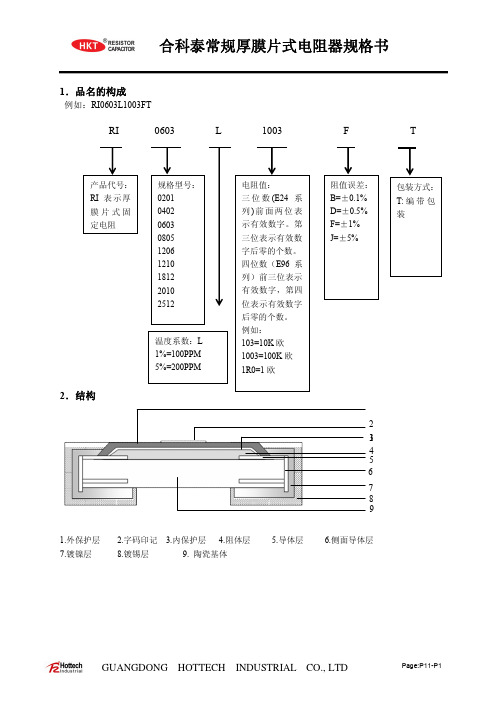
1.品名的构成
例如:RI0603L1003FT
RI
0603
L
1003
F
T
产品代号: RI 表示厚 膜片式固 定电阻
规格型号: 0201 0402 0603 0805 1206 1210 1812 2010 2512
2.结构
温度系数:L 1%=100PPM 5%=200PPM
1Ω~10Ω 10Ω~22MΩ ----------
1Ω~10Ω 10Ω~22MΩ ----------
0ohm Jumper
0ohm Jumper 最大电
流
50mΩ MAX
0.5A
50mΩ
1A
MAX
50mΩ
1A
MAX
50mΩ MAX
1.5A
50mΩ MAX
1.9A
50mΩ MAX
2.2A
50mΩ
3A
1Ω~10Ω 10Ω~10MΩ ----------
1Ω~10Ω 10Ω~10MΩ ----------
1Ω~10Ω 10Ω~10MΩ ----------
1Ω~10Ω 10Ω~10MΩ ----------
1Ω~10Ω 10Ω~10MΩ ----------
J(±5%) E24
1Ω~25Ω
25Ω~10MΩ
1Ω~10Ω ---------10Ω~10MΩ
1Ω~10Ω ---------10Ω~10MΩ
1Ω~10Ω ---------10Ω~10MΩ
1Ω~25Ω
25Ω~10MΩ
1Ω~10Ω 10Ω~10MΩ ----------
1Ω~10Ω 10Ω~10MΩ ----------
深圳市科特翎科技有限公司产品规格书说明书

产品规格书SPECIFICATION产品名称N ame.NO:0805白光White产品型号Model.NO:KTR-0805CWD文件编号Document.NO:MQ8032版次REV.NO:K3.0描述Description:■ 2.0×1.25mm贴片发光二极管2.0×1.25mm Chip SMD ■胶体颜色Colloid Color:黄色Yellow■发光颜色Emission Color:白色White■半功率角度Viewing Angle:120°深圳市科特翎科技有限公司SHENZHEN KETERINE TECHNOLOGY CO.,LTD.编制Prepared by审核Checked by核准Approved by市场部Market Dept.客户确认CUSTOMER CONFIRMATION确认Confirmed by审核Checked by核准Approved by确认Confirmed by1.外形尺寸Dimensions单位(Units):毫米(mm)注意:所有尺寸单位为mm,如无特殊说明误差范围为±0.1mmAll dimensions area in mm tolerance is±0.1mm unless otherwise noted.2.光电特性Electrical/Optical characteristics (1)最大限度值Absolute Maximum Ratings(TA=25±5ºC)项目Item符号Symbol最大额定值Absolute Maximum Rating单位Unit正向电流Forward Current IF20mA正向峰值电流Pulse Forward Current IFP100mA反向电压Reverse Voltage VR5V功率消耗Power Dissipation PD70mW工作温度Operating Temperature Topr-40ºC To+85ºC°C贮藏温度Storage Temperature Tstg-40ºC To+85ºC°C焊接温度Soldering Temperature Tsld ReflowSoldering:260ºC For10sec. 1/10周期,0.1msec脉宽IFP Conditions:1/10Duty Cycle,0.1msec Pulse Width.(2)样品光电参数Initial Electrical/Optical Characteristics(TA=25±5ºC)符号Symbol 项目Item单位Units最小值Min.规格值Typ.最大值Max.测试条件TestConditionsVF正向电压Forward Voltage V 2.6 3.2IF=10mAIR反向电流Reverse Current uA10VR=7V2θ½发光角度Viewing Angleº120ºIF=10mAø发光强度Luminous Intensitymcd6001080IF=10mATC色温Colour Temperature k700011000IF=10mARA显色指数Color Rendering Index Ra7080IF=10mA 正向电压允许误差±0.05V Tolerance of measurement of Vf is±0.05V.亮度允许误差±10%Luminous Intensity Measurement allowance is±10%.3.特性曲线Characteristic curve4.可靠性RELIABILITY (1)测试项目及结果Test Items and Results实验项目Test Items 参考标准Reference实验条件Test Conditions时间Time样品数Quantity判据Criterion冷热冲击Thermal Shock MIL-STD-202G-40℃(30min)←→100℃(30min)循环200次200cycles220/22湿热循环Temperature And Humidity Cyclic JEITA ED-4701200203-10℃——+65℃,0%-90%RH24hrs./1cycle循环10次10cycles220/22高温储存High Temperature Storage JEITA ED-4701200201Ta=100℃1000h220/22低温储存Low Temperature Storage JEITA ED-4701200202Ta=-40℃1000h220/22高温高湿储存High Temperature High Humidity Storage JEITA ED-4701100103Ta=60℃,RH=90%1000h220/22常温寿命试验Life Test JESD22-A108D Ta=25℃IF=20mA1000h220/22高温寿命High Temperature Life Test JESD22-A108D Ta=80℃IF=20mA1000h220/22低温寿命Low Temperature Life Test JESD22-A108D Ta=-40℃IF=20mA1000h220/22耐焊接热Resistance to Soldering Heat GB/T4937,Ⅱ,2.2&2.3Tsol*=260℃10secs.2次2times220/225.注意事项Cautions(1)焊接条件Soldering Conditions本产品最多只可回焊两次,且在首次回焊后须冷却至室温之后方可进行第二次回焊。
杰威尔电子0603包装LED光源数据表说明书

Max.
285.0 --------535 -----
3.95 50
Unit Condition
mcd
deg
nm
nm
IF=20mA
nm V
μA
VR=5V
Everlight Electronics Co., Ltd. Device No:SZDSE-193-G06
Prepared date: 07-27-2005
∫ 5 min
300 Cycles 22 PCS. 0/1
L : -40℃ 15min
H : +100℃ 5min
3
Thermal Shock
∫ 10 sec
300 Cycles 22 PCS. 0/1
L : -10℃ 5min
High Temperature
4
Storage
5
Low Temperature
Rev. 2
Page: 4 of 10
Prepared by: Hao Liu
EVERLIGHT ELECTRONICS CO.,LTD.
19-213/GHC-YR1S2M/3T
Typical Electro-Optical Characteristics Curves
Everlight Electronics Co., Ltd. Device No:SZDSE-193-G06
EVERLIGHT ELECTRONICS CO.,LTD.
Package Outline Dimensions
19-213/GHC-YR1S2M/3T
-
+
Note: The tolerances unless mentioned is ±0.1mm ,Unit = mm
贴片气体放电管型号

贴片气体放电管型号
贴片气体放电管是一种电子元件,也称为气体放电管、气体耦合器、气体变压器等。
它的结构由两个电极和介质组成,工作时在介质中通入特定气体,通过电极间的放电产生特定的电流和电压。
贴片气体放电管种类繁多,常见的有NE-2、NE-2H、NE-2W、NE-2G 等型号。
它们的尺寸、形状、放电电压、电流等参数各不相同,适用于不同的电路和应用场合。
例如,NE-2H适用于高压、高频、高电流的电路中,NE-2W适用于低电压、低功率的电路中。
贴片气体放电管具有耐高压、耐噪声干扰、寿命长等特点,广泛应用于电力、通讯、医疗、航空航天等领域。
- 1 -。
Murata LQW03AW_00系列芯片电容器(芯片导纳)参考规格书说明书
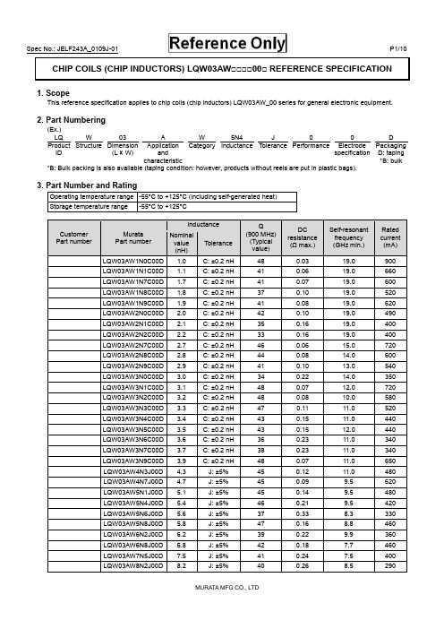
CHIP COILS (CHIP INDUCTORS) LQW03AW□□□□00□ REFERENCE SPECIFICATION1. ScopeThis reference specification applies to chip coils (chip inductors) LQW03AW_00 series for general electronic equipment.2. Part Numbering(Ex.)LQ W 03 A W 5N4 J 0 0 DProductID Structure Dimension(L × W)ApplicationandcharacteristicCategory Inductance Tolerance Performance ElectrodespecificationPackagingD: taping*B: bulk*B: Bulk packing is also available (taping condition: however, products without reels are put in plastic bags).3. Part Number and RatingOperating temperature range -55°C to +125°C (including self-generated heat)Storage temperature range -55°C to +125°CCustomer Part numberMurataPart numberInductance Q(900 MHz)(Typicalvalue)DCresistance(Ω max.)Self-resonantfrequency(GHz min.)Ratedcurrent(mA) Nominalvalue(nH)ToleranceLQW03AW1N0C00D1.0C:±0.2nH 48 0.03 19.0 900 LQW03AW1N1C00D1.1C:±0.2nH 41 0.06 19.0 660 LQW03AW1N7C00D1.7C:±0.2nH 41 0.07 19.0 600 LQW03AW1N8C00D1.8C:±0.2nH 37 0.10 19.0 520 LQW03AW1N9C00D1.9C:±0.2nH 41 0.08 19.0 620 LQW03AW2N0C00D2.0C:±0.2nH 42 0.10 19.0 490 LQW03AW2N1C00D2.1C:±0.2nH 35 0.16 19.0 400 LQW03AW2N2C00D2.2C:±0.2nH 33 0.16 19.0 400 LQW03AW2N7C00D2.7C:±0.2nH 46 0.06 15.0 720 LQW03AW2N8C00D2.8C:±0.2nH 44 0.08 14.0 600 LQW03AW2N9C00D2.9C:±0.2nH 41 0.10 13.0 540 LQW03AW3N0C00D3.0C:±0.2nH 34 0.22 14.0 350 LQW03AW3N1C00D3.1C:±0.2nH 48 0.07 12.0 720 LQW03AW3N2C00D3.2C:±0.2nH 48 0.08 10.0 580 LQW03AW3N3C00D3.3C:±0.2nH 47 0.11 11.0 520 LQW03AW3N4C00D3.4C:±0.2nH 43 0.15 11.0 440 LQW03AW3N5C00D3.5C:±0.2nH 43 0.15 12.0 440 LQW03AW3N6C00D3.6C:±0.2nH 36 0.23 11.0 340 LQW03AW3N7C00D3.7C:±0.2nH 38 0.23 11.0 340 LQW03AW3N9C00D3.9C:±0.2nH 48 0.07 11.0 650 LQW03AW4N3J00D4.3 J:±5% 45 0.12 11.0 480 LQW03AW4N7J00D4.7 J:±5% 45 0.09 9.5 620 LQW03AW5N1J00D5.1 J:±5% 45 0.14 9.5 480 LQW03AW5N4J00D5.4 J:±5% 46 0.21 9.5 420 LQW03AW5N6J00D5.6 J:±5% 37 0.33 8.3 330 LQW03AW5N8J00D5.8 J:±5% 47 0.16 8.8 460 LQW03AW6N2J00D6.2 J:±5% 39 0.22 9.9 360 LQW03AW6N8J00D6.8 J:±5% 42 0.18 7.7 460 LQW03AW7N5J00D7.5 J:±5% 41 0.24 7.5 400 LQW03AW8N2J00D8.2 J:±5% 40 0.26 8.5 290Customer Part numberMurataPart numberInductance Q(900 MHz)(Typicalvalue)DCresistance(Ω max.)Self-resonantfrequency(GHz min.)Ratedcurrent(mA)Nominalvalue(nH)ToleranceLQW03AW8N7J00D8.7J:±5% 39 0.42 7.5 290 LQW03AW9N1J00D9.1J:±5% 46 0.22 6.4 460 LQW03AW10NJ00D10.0J:±5% 37 0.46 7.2 250 LQW03AW11NJ00D11.0J:±5% 37 0.47 7.0 260 LQW03AW12NJ00D12.5J:±5% 39 0.54 6.0 280 LQW03AW13NJ00D13.0J:±5% 39 0.54 5.9 280 LQW03AW14NJ00D13.5J:±5% 37 0.53 6.0 240 LQW03AW15NJ00D15.5J:±5% 38 0.60 5.7 230 4. Testing ConditionsUnless otherwise specified Temperature: ordinary temperature (15°C to 35°C)Humidity: ordinary humidity [25% to 85% (RH)]In case of doubt Temperature: 20°C±2°CHumidity: 60% to 70% (RH)Atmospheric pressure: 86 kPa to 106 kPa5. Appearance and DimensionsUnit mass (typical value): 0.23 mg6. MarkingNo marking.7. Electrical PerformanceNo.ItemSpecificationTest method7.1 InductanceMeet chapter 3 ratings.Measuring equipment: Keysight E4991A or the equivalentMeasuring frequency: Inductance 250 MHz 1.0 nH to 3.9 nH 100 MHz 4.3 nH to 15.5 nH Measuring conditions:Measurement signal level: Approx. 0 dBm Measurement terminal distance: 0.3 mm Electrical length: 10.0 mmMeasuring fixture: Keysight 16197APosition the chip coil under test as shown in the measuring example below and connect it to the electrode by applying weight. Measurement example:Measuring method: see "Electrical performance: Measuring method for inductance/Q" in the chapter"16. Appendix".7.2 QMeet chapter 3 ratings.7.3 DC resistance Meet chapter 3 ratings. Measuring equipment: digital multimeter 7.4 Self-resonantfrequency Meet chapter 3 ratings.Measuring equipment: Keysight N5230A or theequivalent7.5 Rated currentProduct temperature rise: 20°C max.Apply the rated current specified in chapter 3.8. Mechanical PerformanceNo.ItemSpecificationTest method8.1 Bending testNo significant mechanical damage or no sign of electrode peeling off shall be observed. Test substrate: glass-epoxy substrate (100 mm × 40 mm × 0.8 mm) Pressurizing speed: 1 mm/sDeflection: 2 mm Holding time: 5 s8.2 VibrationAppearance shall have no significant mechanical damage.Oscillation frequency: 10 Hz to 55 Hz to 10 Hz, for approx. 1 minTotal amplitude: 1.5 mmTest time: 3 directions perpendicular to each other, 2 h for each direction (6 h in total)No.ItemSpecificationTest method8.3 Solderability90% or more of the outer electrode shall be covered with new solder seamlessly. Flux: immersed in ethanol solution [including anactivator with a chlorine conversion value of 0.06(wt)%]with a rosin content of 25(wt)% for 5 s to 10 s. Solder: Sn-3.0Ag-0.5Cu solderPre-heating: 150°C±10°C/60 s to 90 s Solder temperature: 240°C±5°C Immersion time: 4 s±1 s 8.4 Resistance tosoldering heatAppearance: No significant mechanical damage shall be observed.Inductance change rate: within ±5%Flux: immersed in ethanol solution [including anactivator with a chlorine conversion value of 0.06(wt)%] with a rosin content of 25(wt)% for 5 s to 10 s. Solder: Sn-3.0Ag-0.5Cu solderPre-heating: 150°C±10°C/60 s to 90 s Solder temperature: 270°C±5°C Immersion time: 5 s±1 sPost-treatment: left at a room condition for 24 h±2 h9. Environmental PerformanceThe product is soldered on a substrate for test. No. Item Specification Test method9.1 Heat resistanceAppearance: No significant mechanicaldamage shall be observed.Inductance change rate: within ±5%Q change rate: within ±20%Temperature: 125°C±2°CTest time: 1000 h (+48 h, -0 h)Post-treatment: left at a room condition for 24 h±2 h 9.2 Cold resistanceAppearance: No significant mechanical damage shall be observed.Inductance change rate: within ±5% Q change rate: within ±20%Temperature: -55°C±2°CTest time: 1000 h (+48 h, -0 h)Post-treatment: left at a room condition for 24 h±2 h9.3 HumidityAppearance: No significant mechanical damage shall be observed.Inductance change rate: within ±5% Q change rate: within ±20%Temperature: 70°C±2°CHumidity: 90% (RH) to 95% (RH) Test time: 1000 h (+48 h, -0 h)Post-treatment: left at a room condition for 24 h±2 h 9.4 Temperature cycle Appearance: No significant mechanicaldamage shall be observed.Inductance change rate: within ±5% Q change rate: within ±20%Single cycle conditions:Step 1: -55°C±2°C/30 min±3 minStep 2: ordinary temperature/10 min to 15 min Step 3: +125°C±2°C/30 min±3 minStep 4: ordinary temperature/10 min to 15 min Number of testing: 10 cyclesPost-treatment: left at a room condition for 24 h±2 h10. Specification of Packaging10.1 Appearance and dimensions of tape (8 mm width/paper tape)A (0.52)B (0.65) t 0.75 max.(in mm)10.2 Taping specificationsPacking quantity (Standard quantity) 10000 pcs/reelPacking method The products are placed in embossed cavities of a base tape and sealed by a cover tape.Feed hole position The feed holes on the base tape are on the right side when the cover tape is pulled toward the user. JointThe base tape and the cover tape are seamless.Number of missing productsNumber of missing products within 0.025% of the number per reel or 1 pc., whichever is greater, and are not continuous. The specified quantity per reel is kept.10.3 Break down force of tapeBreak down force of cover tape5 N min.10.4 Peeling off force of cover tapeSpeed of peeling off 300 mm/minPeeling off force0.1 N to 0.6 N (The lower limit is for typical value.)10.5 Dimensions of leader section, trailer section and reelA vacant section is provided in the leader (start) section and trailer (end) section of the tape for the product. The leader section is further provided with an area consisting only of the cover tape (or top tape). (See the diagram below.)10.6 Marking for reelCustomer part number, Murata part number, inspection number (*1), RoHS marking (*2), quantity, etc. *1 Expression of inspection No.: □□ ○○○○(1) (2) (3)(1) Factory code(2) Date First digit: year/last digit of yearSecond digit: month/Jan. to Sep.→1 to 9, Oct. to Dec.→O, N, D Third, Fourth digit: day (3) Serial No.*2 Expression of RoHS marking: ROHS- Y ( ) (1) (2)(1) RoHS regulation conformity(2) Murata classification number10.7 Marking on outer box (corrugated box)Customer name, purchasing order number, customer part number, Murata part number, RoHS marking (*2), quantity, etc.FCover tapetape165°to 180゜10.8 Specification of outer boxDimensions of outer box(mm) Standard reel quantity in outer box (reel)WDH186 186 935* Above outer box size is typical. It depends on a quantity of an order.11. Caution11.1 Restricted applicationsPlease contact us before using our products for the applications listed below which require especially high reliability for the prevention of defects which might directly cause damage to the third party's life, body or property. (1) Aircraft equipment (2) Aerospace equipment (3) Undersea equipment (4) Power plant controlequipment(5) Medical equipment (6) Transportation equipment (vehicles, trains, ships, etc.) (7) Traffic signal equipment (8) Disaster/crimeprevention equipment(9) Data-processing equipment (10) Applications of similar complexity and/or reliability requirements to the applications listed in the above11.2 Precautions on ratingAvoid using in exceeded the rated temperature range, rated voltage, or rated current.Usage when the ratings are exceeded could lead to wire breakage, burning, or other serious fault.11.3 Inrush currentIf an inrush current (or pulse current or rush current) that significantly exceeds the rated current is applied to the product, overheating could occur, resulting in wire breakage, burning, or other serious fault.11.4 Corrosive gasPlease refrain from use since contact with environments with corrosive gases (sulfur gas [hydrogen sulfide, sulfur dioxide, etc.], chlorine, ammonia, etc.) or oils (cutting oil, silicone oil, etc.) that have come into contact with the previously stated corrosive gas environment will result in deterioration of product quality or an open from deterioration due to corrosion of product electrode, etc. We will not bear any responsibility for use under these environments.12. Precautions for UseThis product is for use only with reflow soldering. It is designed to be mounted by soldering. If you want to use other mounting method, for example, using a conductive adhesive, please consult us beforehand.Also, if repeatedly subjected to temperature cycles or other thermal stress, due to the difference in the coefficient of thermal expansion with the mounting substrate, the solder (solder fillet part) in the mounting part may crack.The occurrence of cracks due to thermal stress is affected by the size of the land where mounted, the solder volume, and the heat dissipation of the mounting substrate. Carefully design it when a large change in ambient temperature is assumed.12.1 Land dimensionsThe following diagram shows the recommended land dimensions for reflow soldering.The land dimensions are designed in consideration of electrical characteristics and mountability. Use of other landdimensions may preclude achievement of performance. In some cases, it may result in poor solderability, including positional shift. If you use other land pattern, consider it adequately.a 0.23b 0.65c 0.4(in mm)WDLabelH12.2 Flux and solder usedFlux• Use a rosin-based flux that includes an activator with a chlorine conversion value of 0.06(wt)% to 0.1(wt)%. • Do not use a highly acidic flux with a halide content exceeding 0.2(wt)% (chlorine conversion value). • Do not use a water-soluble flux.Solder• Use Sn-3.0Ag-0.5Cu solder.• Standard thickness of solder paste: 80 μm to 100 μmIf you want to use a flux other than the above, please consult our technical department.12.3 Soldering conditions (reflow)• Pre-heating should be in such a way that the temperature difference between solder and product surface is limited to 150°C max.Cooling into solvent after soldering also should be in such a way that the temperature difference is limited to 100°C max. Insufficient pre-heating may cause cracks on the product, resulting in the deterioration of product quality. • Standard soldering profile and the limit soldering profile is as follows.The excessive limit soldering conditions may cause leaching of the electrode and/or resulting in the deterioration of product quality.Standard profile Limit profilePre-heating 150°C to 180°C/90 s±30 s 150°C to 180°C/90 s±30 s HeatingAbove 220°C/30 s to 60 sAbove 230°C/60 s max.Peak temperature 245°C±3°C 260°C/10 s Number of reflow cycles2 times2 times12.4 Reworking with soldering ironDo not perform reworking with a soldering iron on this product.12.5 Solder volumeSolder shall be used not to increase the volume too much.An increased solder volume increases mechanical stress on the product. Exceeding solder volume may cause the failure of mechanical or electrical performance.Limit ProfileStandard Profile90s±30s230℃260℃245℃±3℃220℃30s~60s60s max.180150Temp.(s)(℃)Time.12.6 Product's locationThe following shall be considered when designing and laying out PCBs.(1) PCB shall be designed so that products are not subject to mechanical stress due to warping the board. [Products direction]Products shall be located in the sideways direction (length: a < b) to the mechanical stress.(2) Components location on PCB separationIt is effective to implement the following measures, to reduce stress in separating the board.It is best to implement all of the following three measures; however, implement as many measures as possible to reduce stress.Contents of measures Stress level(1) Turn the mounting direction of the component parallel to theboard separation surface.A > D *1 (2) Add slits in the board separation part.A >B (3) Keep the mounting position of the component away from the board separation surface.A > C*1 A > D is valid when stress is added vertically to the perforation as with hand separation. If a cutting disc is used, stress will be diagonal to the PCB, therefore A > D is invalid.(3) Mounting components near screw holesWhen a component is mounted near a screw hole, it may be affected by the board deflection that occurs during the tightening of the screw.Mount the component in a position as far away from the screw holes as possible.12.7 Handling of substrateAfter mounting products on a substrate, do not apply any stress to the product caused by bending or twisting to the substrate when cropping the substrate, inserting and removing a connector from the substrate or tightening screw to the substrate. Excessive mechanical stress may cause cracking in the product.Bending Twisting〈Poor example 〉〈Good example〉ba12.8 CleaningThe product shall be cleaned under the following conditions.(1) The cleaning temperature shall be 60°C max. If isopropyl alcohol (IPA) is used, the cleaning temperature shall be 40°Cmax.(2) Perform ultrasonic cleaning under the following conditions. Exercise caution to prevent resonance phenomenon inmounted products and the PCB.Item RequirementPower 20 W/L max.Time 5 min max.Frequency 28 kHz to 40 kHz(3) CleanerAlcohol-based cleaner: IPAAqueous agent: PINE ALPHA ST-100S(4) There shall be no residual flux or residual cleaner. When using aqueous agent, rinse the product with deionized wateradequately and completely dry it so that no cleaner is left.* For other cleaning, consult our technical department.12.9 Storage and transportationStorage period Use the product within 12 months after delivery.If you do not use the product for more than 12 months, check solderability before using it.Storage conditions • The products shall be stored in a room not subject to rapid changes in temperature and humidity.The recommended temperature range is -10°C to +40°C. The recommended relative humidityrange is 15% to 85%.Keeping the product in corrosive gases, such as sulfur, chlorine gas or acid, oxidizes theelectrode, resulting in poor solderability or corrosion of the coil wire of the product.• Do not keep products in bulk packaging. Doing so may cause collision between the products orbetween the products and other products, resulting in core chipping or wire breakage.• Do not place the products directly on the floor; they should be placed on a palette so that they arenot affected by humidity or dust.• Avoid keeping the products in a place exposed to direct sunlight, heat or vibration.Transportation Excessive vibration and impact reduces the reliability of the products. Exercise caution whenhandling the products.12.10 Resin coatingThe inductance value may change due to high cure-stress of resin to be used for coating/molding products.A wire breakage issue may occur by mechanical stress caused by the resin, amount/cured shape of resin, or operatingcondition etc. Some resin contains some impurities or chloride possible to generate chlorine by hydrolysis under some operating condition may cause corrosion of wire of coil, leading to wire breakage.So, please pay your careful attention when you select resin in case of coating/molding the products with the resin.Prior to use the coating resin, please make sure no reliability issue is observed by evaluating products mounted on your board.12.11 Handling of product• Sharp material such as a pair of tweezers or other material such as bristles of cleaning brush, shall not be touched to the winding portion to prevent the breaking of wire.• Mechanical shock should not be applied to the products mounted on the board to prevent the breaking of the core.12.12 Handling with mounting equipment• With some types of mounting equipment, a support pin pushes up the product from the bottom of the base (paper) tape when the product is sucked with the pick-up nozzle.When using this type of equipment, detach the support pin to prevent the breaking of wire on the product.• In some cases, the laser recognition function of the mounting equipment may not recognize this product correctly.Please contact us when using laser recognition. (There is no problem with the permeation and reflection type.)13. Note(1) Please make sure that your product has been evaluated in view of your specifications with our product being mounted toyour product.(2) You are requested not to use our product deviating from the reference specifications.(3) The contents of this reference specification are subject to change without advance notice. Please approve our productspecifications or transact the approval sheet for product specifications before ordering.14. AppendixElectrical performance: Measuring method for inductance/Q (Q measurement is applicable only when the Q value is included in the rating table.)Perform measurement using the method described below. (Perform correction for the error deriving from the measuring terminal.)(1) Residual elements and stray elements of the measuring terminal can be expressed by the F parameter for the 2-poleterminal as shown in the figure below.(2) The product's impedance value (Zx) and measured impedance value (Zm) can be expressed as shown below, by usingthe respective current and voltage for input/output.Zm=V1I1Zx=V2I2(3) Thus, the relationship between the product's impedance value (Zx) and measured impedance value (Zm) is as follows.Zx=αZm-β1-ZmΓHere,α=D/A=1β=B/D=Zsm - (1 - Yom Zsm) ZssΓ=C/A=YomZsm: measured impedance of short chipZss: residual impedance of short chip (0.480 nH)Yom: measured admittance when measuring terminal is open (4) Calculate inductance Lx and Qx using the equations shown below.Lx=Im (Zx)2πfLx: inductance of chip coilQx: Q of chip coilf: measuring frequencyQx=Im (Zx) Re (Zx)。
tht类型元件

THT类型元件什么是THT类型元件THT(Through-Hole Technology)类型元件是一种电子元件安装技术,其特点是通过将元件引脚插入印刷电路板(PCB)上的孔中,并通过焊接来固定元件。
THT类型元件通常具有较大的尺寸和插脚,适用于手工和半自动焊接工艺。
THT类型元件的分类THT类型元件可以根据其功能和特性进行分类。
以下是一些常见的THT类型元件:1.电阻器(Resistors):电阻器是一种用于限制电流流动的电子元件。
它们通常由陶瓷或金属制成,具有两个引脚,用于将其插入PCB上的孔中。
2.电容器(Capacitors):电容器是一种用于存储电荷的元件。
它们由两个导体板之间的电介质隔开,并具有两个引脚,用于插入PCB上的孔中。
3.二极管(Diodes):二极管是一种具有两个电极(阳极和阴极)的元件。
它们用于控制电流的方向,并具有一个引脚插入PCB上的孔中。
4.三极管(Transistors):三极管是一种具有三个电极(基极、发射极和集电极)的元件。
它们用于放大和开关电流,并通过将引脚插入PCB上的孔中进行连接。
5.继电器(Relays):继电器是一种电磁开关,用于控制较大电流的流动。
它们由线圈和多个触点组成,并通过将引脚插入PCB上的孔中进行连接。
6.音频插孔(Audio Jacks):音频插孔用于连接音频设备,例如耳机或扬声器。
它们具有多个引脚,用于插入PCB上的孔中,并传输音频信号。
7.开关(Switches):开关用于打开或关闭电路。
它们通常具有一个或多个引脚,用于插入PCB上的孔中,并通过切换来控制电路的连接。
THT类型元件的优点和应用THT类型元件具有以下优点:1.稳定性:由于THT类型元件通过插入孔并焊接到PCB上,因此它们通常比其他类型的元件更牢固和稳定。
2.适应性:THT类型元件适用于手工和半自动焊接工艺,使其在小批量生产和原型制作中非常有用。
3.可靠性:由于THT类型元件的焊接连接较为牢固,它们在振动和环境变化下的可靠性较高。
FENGHUA风华高科
通用型系列片容
0805B/822J500NB
通用型系列片容
0603CG0R1C500NB
通用型系列片容
0805F/564M160NB
通用型系列片容
1206CG112J500NB
通用型系列片容
1812F/684Z500NT
高Q型片容
高Q型片容
0402HQ3R0B500NT
直流中高压片容
1210B/105K101NT
直流中高压片容
3035B/105K501NT
排容
6124B/102M500NT
排容
6124F/223M500NB
排容
6124B/103K101NT
排容
6124B/471M160NT
排容
6124CG220M500NT
排容
6124B/473K160NT
Y212CG560J302NB
安规片容
Y212B/681K302NT
柔性端头片容
1206CG221J501AT
柔性端头片容
1812B/223M101AT
柔性端头片容
1812B/474M101AT
柔性端头片容
2220B/225M101AT
柔性端头片容
0805B/222K501AB
开路模式片容
开路模式片容
OP10B/104K101NT
开路模式片容
OP05B/102K101NT
开路模式片容
OP10B/104M101NT
开路模式片容
OP05B/102K101NT
RQA0009SXTL-E中文资料

RQA0009SXAQSSilicon N-Channel MOS FETREJ03G1566-0100Rev.1.00Jul 04, 2007Features• High Output Power, High Gain, High EfficiencyPout = +37.8 dBm, Linear Gain = 18 dB, PAE = 65%(V DS = 6 V, f = 520 MHz)• Compact package capable of surface mounting• Electrostatic Discharge Immunity Test(IEC Standard, 61000-4-2, Level4)Outline*UPAK is a trademark of Renesas Technology Corp.Absolute Maximum Ratings(Ta = 25°C)UnitRatingsItem SymbolDrain to source voltage V DSS 16 V Gate to source voltage V GSS ±5 V Drain current I D 3.2 A Channel dissipation Pch note 15 W Channel temperature Tch 150 °CStorage temperature Tstg –55 to +150 °CNote: Value at Tc = 25°CThis device is sensitive to electro static discharge. An adequate careful handling procedure is requested.Electrical Characteristics(Ta = 25°C)Item Symbol Min. Typ Max. Unit Test ConditionsZero gate voltage drain current I DSS — — 15 µA V DS = 16 V, V GS = 0 Gate to source leak current I GSS — — ±2 µA V GS = ±5 V, V DS = 0 Gate to source cutoff voltage V GS(off) 0.15 0.5 0.8 V V DS = 6 V, I D = 1 mA Forward Transfer Admittance |yfs| — 3.2 — S V DS = 6 V, I D = 1.6 A Input capacitance Ciss — 76 — pF V GS = 5 V, V DS = 0, f = 1 MHz Output capacitance Coss — 40 — pF V DS = 6 V, V GS = 0, f = 1 MHz Reverse transfer capacitance Crss — 3.5 — pF V DG = 6 V, V GS = 0, f = 1 MHz — 37.8 — dBm Output Power Pout — 6.0 — WPower Added Efficiency PAE — 65 — %V DS = 6 V, I DQ = 180 mAf = 520 MHz, Pin = +25 dBm (316 mW) — 35.2 — dBm Output Power Pout — 3.3 — WPower Added Efficiency PAE — 60 — % V DS = 4.8 V, I DQ = 300 mAf = 465 MHz,Pin = +17 dBm (50 mW)Main CharacteristicsEvaluation Circuit (f = 520 MHz)Evaluation Circuit (f = 465 MHz)S Parameter(V DS = 6 V, I DQ = 180 mA, Zo = 50 Ω)S11 S21 S12 S22(deg.) MAG ANG(deg.)(deg.)MAG ANGf(MHz) MAG ANG(deg.) MAG ANG100 0.868 -154.0 9.85 88.8 0.019 1.2 0.706 -166.8 150 0.861 -159.4 5.42 77.2 0.018 -6.3 0.725 -168.9 200 0.882 -163.9 3.64 68.2 0.016 -14.1 0.755 -170.6 250 0.892 -166.8 2.64 58.5 0.016 -19.2 0.768 -170.6 300 0.899 -169.5 2.06 51.8 0.014 -22.1 0.792 -171.2 350 0.910 -171.6 1.61 45.1 0.013 -27.2 0.805 -171.5 400 0.918 -173.4 1.28 40.3 0.013 -29.3 0.827 -172.2 450 0.926 -175.2 1.04 36.0 0.011 -34.1 0.840 -173.1 500 0.932 -176.8 0.84 31.8 0.010 -33.1 0.855 -173.8 550 0.936 -178.2 0.73 28.8 0.009 -34.5 0.869 -174.6 600 0.940 -179.5 0.62 26.4 0.008 -34.6 0.880 -175.6 650 0.941 179.2 0.54 23.1 0.007 -36.5 0.892 -176.5 700 0.944 178.1 0.45 20.2 0.006 -32.7 0.901 -177.3 750 0.945 176.9 0.41 18.3 0.006 -32.0 0.906 -178.0 800 0.944 175.9 0.37 16.4 0.005 -25.3 0.915 -179.4 850 0.944 174.6 0.31 13.9 0.004 -22.3 0.919 180.0 900 0.943 173.4 0.30 12.1 0.004 -15.2 0.929 178.9 950 0.943 172.3 0.26 10.6 0.003 0.3 0.930 178.1 1000 0.946 171.1 0.23 8.6 0.003 9.1 0.936 177.2 1050 0.949 170.2 0.22 7.3 0.003 20.6 0.940 176.5 1100 0.951 169.4 0.21 6.5 0.004 36.9 0.943 175.5 1150 0.952 168.7 0.18 5.3 0.004 40.3 0.944 174.7 1200 0.952 167.8 0.18 4.3 0.004 52.0 0.950 174.1 1250 0.952 167.0 0.16 3.7 0.005 53.2 0.951 173.3 1300 0.952 166.2 0.14 2.2 0.005 56.8 0.949 172.6 1350 0.952 165.4 0.14 1.3 0.006 60.9 0.956 171.7 1400 0.952 164.6 0.13 0.8 0.006 64.0 0.958 171.0 1450 0.952 164.0 0.12 0.1 0.007 62.2 0.957 170.3 1500 0.952 163.3 0.11 -0.8 0.008 65.4 0.956 169.5 1550 0.952 162.1 0.11 -1.8 0.008 65.9 0.959 168.5 1600 0.952 160.8 0.10 -2.7 0.009 65.6 0.960 168.2 1650 0.952 159.7 0.10 -3.6 0.009 65.9 0.960 167.4 1700 0.952 158.5 0.09 -4.5 0.010 66.6 0.962 166.4 1750 0.952 157.3 0.08 -4.7 0.010 66.2 0.967 165.8 1800 0.952 156.4 0.08 -5.0 0.011 66.5 0.968 165.3 1850 0.952 155.7 0.08 -4.7 0.011 66.5 0.965 164.5 1900 0.953 154.7 0.07 -4.9 0.012 67.0 0.967 163.7 1950 0.958 153.9 0.07 -5.2 0.012 67.0 0.976 163.2 2000 0.965 153.6 0.07 -4.6 0.013 65.5 0.972 162.9 2050 0.963 153.3 0.07 -4.9 0.013 65.4 0.972 161.9 2100 0.956 152.9 0.06 -4.2 0.014 65.3 0.976 161.0 2150 0.950 152.2 0.06 -3.5 0.014 65.2 0.981 160.7 2200 0.944 151.6 0.06 -3.8 0.015 63.9 0.977 160.1 2250 0.936 150.7 0.06 -3.5 0.015 63.9 0.977 159.5 2300 0.932 149.3 0.05 -3.4 0.016 63.0 0.978 158.9 2350 0.932 148.1 0.05 -3.6 0.016 62.8 0.981 158.4 2400 0.929 147.3 0.05 -3.0 0.017 63.0 0.977 158.0 2450 0.923 146.3 0.05 -3.6 0.017 61.3 0.977 157.2 2500 0.917 144.9 0.05 -3.0 0.017 61.8 0.980 156.8S Parameter(V DS = 4.8 V, I DQ = 300 mA, Zo = 50 Ω)S11 S21 S12 S22(deg.) MAG ANG(deg.)(deg.)MAG ANGf(MHz) MAG ANG(deg.) MAG ANG100 0.772 -157.0 9.63 88.9 0.013 -1.0 0.776 -172.1 150 0.794 -162.8 5.54 79.0 0.013 -6.3 0.784 -173.8 200 0.812 -167.3 3.91 71.6 0.012 -11.1 0.799 -174.8 250 0.818 -170.4 2.98 64.7 0.011 -13.5 0.805 -174.8 300 0.824 -173.1 2.36 59.1 0.011 -15.2 0.818 -175.0 350 0.831 -175.0 1.92 53.6 0.011 -20.4 0.824 -175.1 400 0.836 -176.6 1.60 48.7 0.010 -21.4 0.837 -175.4 450 0.841 -178.3 1.36 44.8 0.009 -23.3 0.843 -175.8 500 0.848 -179.9 1.15 40.5 0.008 -22.9 0.859 -176.8 550 0.851 179.0 1.00 37.1 0.008 -22.2 0.868 -177.1 600 0.851 177.7 0.87 33.9 0.007 -24.8 0.874 -177.4 650 0.852 176.3 0.77 30.7 0.006 -24.2 0.887 -177.8 700 0.854 174.7 0.69 27.9 0.006 -20.5 0.896 -178.8 750 0.858 173.3 0.60 24.8 0.005 -18.2 0.901 -179.1 800 0.865 171.9 0.54 22.3 0.005 -15.1 0.905 -179.8 850 0.873 170.8 0.49 20.2 0.005 -12.2 0.911 179.5 900 0.878 169.8 0.45 17.9 0.004 -1.7 0.918 178.9 950 0.880 168.8 0.41 16.1 0.004 4.3 0.922 178.3 1000 0.882 167.7 0.37 14.2 0.004 11.2 0.932 177.8 1050 0.886 166.5 0.35 12.4 0.004 21.6 0.931 177.1 1100 0.889 165.5 0.32 10.7 0.004 29.8 0.935 176.5 1150 0.893 164.4 0.29 8.9 0.004 33.2 0.939 175.8 1200 0.898 163.3 0.27 7.5 0.004 40.9 0.944 175.1 1250 0.902 162.4 0.26 6.2 0.005 46.7 0.943 174.6 1300 0.901 161.3 0.23 4.7 0.005 50.8 0.948 174.1 1350 0.902 160.0 0.22 3.3 0.005 54.5 0.948 173.4 1400 0.904 158.7 0.21 1.8 0.006 57.8 0.954 173.1 1450 0.907 157.7 0.19 0.4 0.006 55.3 0.954 172.5 1500 0.904 156.5 0.18 -0.8 0.007 60.5 0.953 171.6 1550 0.905 155.1 0.17 -2.4 0.007 62.1 0.958 171.0 1600 0.912 153.8 0.16 -3.1 0.007 61.1 0.959 170.7 1650 0.915 152.8 0.15 -4.2 0.008 64.3 0.956 170.4 1700 0.919 151.5 0.14 -5.8 0.008 63.2 0.958 169.3 1750 0.926 149.9 0.14 -6.8 0.009 62.7 0.964 168.9 1800 0.938 148.8 0.13 -7.8 0.009 63.0 0.965 168.4 1850 0.942 147.9 0.13 -8.6 0.010 62.6 0.963 167.8 1900 0.942 146.7 0.12 -9.3 0.010 61.9 0.965 167.0 1950 0.945 145.5 0.11 -10.2 0.010 63.8 0.968 166.6 2000 0.946 144.7 0.11 -10.6 0.011 62.4 0.965 166.3 2050 0.942 143.7 0.11 -11.2 0.011 62.2 0.969 165.5 2100 0.939 142.3 0.10 -11.8 0.012 61.2 0.973 164.9 2150 0.940 140.9 0.10 -12.5 0.012 62.0 0.974 164.6 2200 0.942 139.8 0.09 -13.3 0.012 61.3 0.974 164.2 2250 0.939 138.3 0.09 -14.3 0.013 59.2 0.974 163.4 2300 0.937 136.8 0.08 -15.3 0.013 59.6 0.976 163.0 2350 0.937 135.4 0.08 -16.3 0.014 59.8 0.977 162.9 2400 0.935 134.1 0.08 -17.5 0.014 58.9 0.972 162.0 2450 0.932 132.8 0.07 -18.1 0.014 57.9 0.975 161.5 2500 0.931 131.3 0.07 -18.7 0.014 57.7 0.977 161.2Package DimensionsOrdering InformationPart Name Quantity Shipping Containerφ178 mm reel, 12 mm emboss tapingpcs.RQA0009SXTL-E 1000Refer to "/en/network " for the latest and detailed information.Renesas Technology America, Inc.450 Holger Way, San Jose, CA 95134-1368, U.S.A Tel: <1> (408) 382-7500, Fax: <1> (408) 382-7501Renesas Technology Europe LimitedDukes Meadow, Millboard Road, Bourne End, Buckinghamshire, SL8 5FH, U.K.Tel: <44> (1628) 585-100, Fax: <44> (1628) 585-900Renesas Technology (Shanghai) Co., Ltd.Unit 204, 205, AZIACenter, No.1233 Lujiazui Ring Rd, Pudong District, Shanghai, China 200120Tel: <86> (21) 5877-1818, Fax: <86> (21) 6887-7898Renesas Technology Hong Kong Ltd.7th Floor, North Tower, World Finance Centre, Harbour City, 1 Canton Road, Tsimshatsui, Kowloon, Hong Kong Tel: <852> 2265-6688, Fax: <852> 2730-6071Renesas Technology Taiwan Co., Ltd.10th Floor, No.99, Fushing North Road, Taipei, Taiwan Tel: <886> (2) 2715-2888, Fax: <886> (2) 2713-2999Renesas Technology Singapore Pte. Ltd.1 Harbour Front Avenue, #06-10, Keppel Bay Tower, Singapore 098632 Tel: <65> 6213-0200, Fax: <65> 6278-8001Renesas Technology Korea Co., Ltd.Kukje Center Bldg. 18th Fl., 191, 2-ka, Hangang-ro, Yongsan-ku, Seoul 140-702, Korea Tel: <82> (2) 796-3115, Fax: <82> (2) 796-2145Renesas Technology Malaysia Sdn. BhdUnit 906, Block B, Menara Amcorp, Amcorp Trade Centre, No.18, Jalan Persiaran Barat, 46050 Petaling Jaya, Selangor Darul Ehsan, Malaysia Tel: <603> 7955-9390, Fax: <603> 7955-9510RENESAS SALES OFFICES。
- 1、下载文档前请自行甄别文档内容的完整性,平台不提供额外的编辑、内容补充、找答案等附加服务。
- 2、"仅部分预览"的文档,不可在线预览部分如存在完整性等问题,可反馈申请退款(可完整预览的文档不适用该条件!)。
- 3、如文档侵犯您的权益,请联系客服反馈,我们会尽快为您处理(人工客服工作时间:9:00-18:30)。
RQK0603CGDQA
Silicon N Channel MOS FET
Power Switching
REJ03G1277-0400
Rev.4.00
Jun 15, 2006
Features
• Low on-resistance
R DS(on) = 212 mΩ typ (V GS = 10 V, I D = 1 A)
• Low drive current
• High speed switching
• 4.5 V gate drive
Outline
Absolute Maximum Ratings
(Ta = 25°C)
Unit
Ratings
Item Symbol
Drain to source voltage V DSS 60 V
Gate to source voltage V GSS ±20 V
Drain current I D 2 A
Drain peak current I D(Pulse) Note1 5 A
Body - drain diode reverse drain current I DR 2 A Channel dissipation Pch Note2 0.8 W
Channel temperature Tch 150 °C
Storage temperature Tstg –55 to +150 °C
Notes: 1. PW ≤ 10 µs, duty cycle ≤ 1%
2. When using the glass epoxy board (FR-4: 40 × 40 × 1 mm)
Electrical Characteristics
(Ta = 25°C)
Item Symbol Min Typ Max Unit Test conditions
Drain to source breakdown voltage V (BR)DSS 60 — — V I D = 10 mA, V GS = 0 Gate to source breakdown voltage V (BR)GSS ±20 — — V I G = ±100 µA, V DS = 0 Gate to source leak current I GSS — — ±10 µA V GS = ±16 V, V DS = 0 Drain to source leak current I DSS — — 1 µA V DS = 60 V, V GS = 0 Gate to source cutoff voltage V GS(off) 1.0 — 2.0 V V DS = 10 V, I D = 1 mA R DS(on) — 212 265 m Ω I D = 1 A, V GS = 10 V Note3 Drain to source on state resistance R DS(on) — 248 348 m Ω
I D = 1 A, V GS = 4.5 V Note3
Forward transfer admittance |y fs | 1.6 2.7 — S I D = 1 A, V DS = 10 V Note3 Input capacitance Ciss — 130 — pF Output capacitance
Coss — 24 — pF Reverse transfer capacitance Crss — 9 — pF
V DS = 10 V, V GS = 0,
f = 1 MHz Turn - on delay time t d(on) — 7.3 — ns Rise time
t r — 35 — ns Turn - off delay time t d(off) — 44 — ns
Fall time
t f — 6.5 — ns I D = 0.75 A, V GS = 10 V,
R L = 13 Ω, Rg = 4.7 Ω Total gate charge
Qg — 2.8 — nC Gate to source charge Qgs — 0.4 — nC Gate to drain charge
Qgd — 0.4 — nC
V DD = 10 V, V GS = 10 V,
I D = 2 A Body - drain diode forward voltage V DF — 0.9 — V I F = 1.5 A, V GS = 0 Note3
Notes: 3. Pulse test
Main Characteristics
Package Dimensions
Ordering Information
Part Name Quantity Shipping Container
pcs. φ178 mm reel, 8 mm Emboss taping RQK0603CGDQATL-E 3000
RENESAS SALES OFFICES
Refer to "/en/network" for the latest and detailed information.
Renesas Technology America, Inc.
450 Holger Way, San Jose, CA 95134-1368, U.S.A
Tel: <1> (408) 382-7500, Fax: <1> (408) 382-7501
Renesas Technology Europe Limited
Dukes Meadow, Millboard Road, Bourne End, Buckinghamshire, SL8 5FH, U.K.
Tel: <44> (1628) 585-100, Fax: <44> (1628) 585-900
Renesas Technology (Shanghai) Co., Ltd.
Unit 204, 205, AZIACenter, No.1233 Lujiazui Ring Rd, Pudong District, Shanghai, China 200120
Tel: <86> (21) 5877-1818, Fax: <86> (21) 6887-7898
Renesas Technology Hong Kong Ltd.
7th Floor, North Tower, World Finance Centre, Harbour City, 1 Canton Road, Tsimshatsui, Kowloon, Hong Kong
Tel: <852> 2265-6688, Fax: <852> 2730-6071
Renesas Technology Taiwan Co., Ltd.
10th Floor, No.99, Fushing North Road, Taipei, Taiwan
Tel: <886> (2) 2715-2888, Fax: <886> (2) 2713-2999
Renesas Technology Singapore Pte. Ltd.
1 Harbour Front Avenue, #06-10, Keppel Bay Tower, Singapore 098632
Tel: <65> 6213-0200, Fax: <65> 6278-8001
Renesas Technology Korea Co., Ltd.
Kukje Center Bldg. 18th Fl., 191, 2-ka, Hangang-ro, Yongsan-ku, Seoul 140-702, Korea
Tel: <82> (2) 796-3115, Fax: <82> (2) 796-2145
Renesas Technology Malaysia Sdn. Bhd
Unit 906, Block B, Menara Amcorp, Amcorp Trade Centre, No.18, Jalan Persiaran Barat, 46050 Petaling Jaya, Selangor Darul Ehsan, Malaysia
Tel: <603> 7955-9390, Fax: <603> 7955-9510
© 2006. Renesas Technology Corp., All rights reserved. Printed in Japan.。