HF94F-11A2772XXX中文资料
全系列产品电子样本
上海奉申制冷控制器有限公司
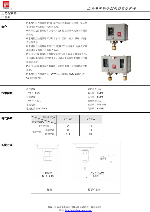
MP45 系列小型压力控制器是一种用压力信号来控制的电开关,它是以压缩机的排气压力 为动作信号来控制压缩机的启停,当压缩机的排气压力超过调定值时,切断电源,起到压 力保护作用。
型号说明
型号
MP45
F
01
B
11
D
3
T
2.6
说明
型号代码 MP45M 为手动复 位形式
连接形式 代号 W
额定电压(V)
额定电流(A) 非诱导电流
诱导电流
满载电流 瞬时电流
A.C. 110
24 24 144
A.C.220
16 16 96
○1 : 公共触点 ○1 -○3 : 温度上升时闭合 ○1 -○5 :温度下降时闭合
↑M: 手动复位方向
版权归上海奉申制冷控制器有限公司所有,翻版必究! 网址:
自动
1.2 1.05
0.5→3.0 0.5→3.0
0.50~1.0 0.3~0.5
固定
自动 自动
2.0 1.5 2.0 1.5
0.5→3.0 固定≥0.4
手动
2.0 ≤1.6
0.3~0.5
0.5→3.0
自动 自动 0.3 0.2 2.0 1.5
固定
0.5→3.0 固定≥0.4 自动 手动 0.3 0.2 2.0 ≤1.6
标准附件及尺寸
版权归上海奉申制冷控制器有限公司所有,翻版必究! 网址:
压力控制器 P 系列
触点形式
形式
低压
型号 P2,P3,P6,P10
P6M
复位形式 自动 手动
P12D,P16D,P20D,P30D
自动
上海奉申制冷控制器有限公司
HF数显示推拉力计说明书
二、HF系列推拉力计外形结构 HF series push pull force gauge external structure
5 上限指示灯
Upper limit indicator light
7 通讯接口
Communication interface
8 电平信号输出接口
Level signals output interface
大一倍的量程。 ( 4 )、 请 勿 在 水 、 油 或 其 他 液 体 溅 到 的 地 方 使 用 推 拉 力 计 , 要 将 推 拉 力 计 存 放 在
阴凉干燥、无振动的地方。 ( 5 )、 请 使 用 配 套 的 充 电 器 充 电 , 绿 灯 亮 时 电 池 已 充 满 , 使 用 中 可 以 同 时 进 行 充
量 程 时 还 会 有 “k N” 或 小 量 程 时 会 出 现 “g f” 。 ③、电池电量指示,当电池电量小于 时请及时充电,当电池电量小于 时 会自动关机。 ④、存储数据的内存编号 ⑤、数据平均值记忆值指示:“AVE. ”表示平均值状态,“MEM. ”表示记忆
值状态。 ⑥、工作模式指示
“T R A C K” : 重 量 跟 踪 模 式 ; “P EA K” : 峰 值 保 持 模 式 ;
17.5 41
四、安全注意事项
(1)、使用前请详细阅读本说明书 , 错误的操作有可能会损坏本机或发生严重 事故。
( 2 )、 在 做 破 坏 试 验 时 , 应 做 好 防 护 工 作 。 ( 3 )、 试 验 前 要 详 细 检 查 安 装 夹 具 , 请 勿 使 用 损 坏 或 弯 曲 变 形 的 夹 具 。 ( 4 )、 传 感 器 负 荷 超 出 额 定 负 荷 的1 0 0 %时 显 示 屏 会 提 示 警 告 信 息,此 时 应 立 刻 减 小
常用光电耦合器参数表

35
6
0.2
18/18
5.3 kV
H11A817D
FSC
300
600
35
6
0.2
18/18
5.3kV
4 脚,光电耦合器 (4 Pin Optocouplers)----GaAs 输入,光电晶体管输出
Part
Number
厂牌
CTR @
10 mA IF(%)
BVCEO
(V)
min
BVCBO
(V)
min
--
--
5.3 kV
MOC8111
20
--
30
7
20/20
5.3 kV
MOC8112
50
--
30
7
20/20
5.3 kV
MOC8113
100
--
30
7
20/20
5.3 kV
SL5582.W
40
320
50
7
20/50
3.75kV
6 脚,光电耦合器 (6 Pin Optocouplers)---GaAs 输入,高电压光电晶体管输出
50
150
35
6
0.2
4/18
5.0kV
H11AA814
Fairchild
20
300
35
6
0.2
--
5.3 kV
H11AA814A
FAIRCHILD
50
150
35
6
0.2
--
5.3 kV
LTV814A
LITEON
50
150
35
HF电机参数总一览表

HF 伺服电机 参数一览表整理:上海宇松技术部 日期:2010-7-232010.07.23宇松赵国胜M60SM60SM60SR-V1-20/40D-SVJ3-07D-V1-20DM-V3-20/40R-V1-20/40D-SVJ3-07D-V1-40DM-SPV3DM-V3-40R-V1-20/40D-SVJ3-10D-V1-40DM-SPV3DM-V3-40参数号代号解释SV001PC1马达侧齿轮比11111111111111SV002PC2机械侧齿轮比11111111111111SV003PGN1位置回路增益13333333333333333333333333333SV004PGN2位置回路增益200000000000000SV005VGN1速度回路增益1152210010040100100100455045100100100SV006VGN2速度回路增益200000000000000SV007-00000000000000SV008VIA 速度回路前进补偿13641364136413641364136413641364136413641364136413641364SV009IQA 前进电流回路q轴补偿6144204802048020480614420480204801024020480614415360102401024010240SV010IDA 前进电流回路d轴补偿6144204802048020480614420480204801024020480614415360102401024010240SV011IQG 电流回路q轴增益76817927687681280307230721280307210242560128012801280SV012IDG 电流回路d轴增益76817927687681280307230721280307210242560128012801280SV013ILMT 电流极限值1500800800800500800800800800500800800800800SV014ILMTsp 电流极限值(特殊控制用)500800800800500800800800800500800800800800SV015FFC 加速度前馈进给增益00000000000000SV016LMC1失位运动补正增益100000000000000SV017SPEC1绝对值伺服系统规格1000001000/14001000001400100010000014001000SV018PIT 导螺杆螺距——___—————__——_____SV019RNG1位置检测器分辨率/A42/A4260/1000260/1000260/1000260/1000260/1000260/1000260/1000260/1000260/1000260/1000260/1000260/1000260/1000260/1000SV020RNG2速度检测器分辨率/A42/A4260/1000260/1000260/1000260/1000260/1000260/1000260/1000260/1000260/1000260/1000260/1000260/1000260/1000260/1000SV021OLT 过负载时间常数6060606060606060606060606060SV022OLL 过负载检测等级150150150150150150150150150150150150150150SV023OD1误差宽度1(伺服ON时)66666666666666SV024INP 定位宽度5050505050505050505050505050SV025MTYP 马达型号221D 2201220122012210220322032203220322112204220422042204SV026OD2误差宽度2(伺服OFF时)66666666666666SV027SSF1特殊伺服机能选择 140004000400040004000400040004000400040004000400040004000SV028-00000000000000SV029VCS 速度变换时的速度回路增益00000000000000SV030IVC 电压不感带补正00000000000000SV031-00000000000000SV032TOF 转矩补正增益00000000000000SV033SSF2特殊伺服机能选择 200000000SV034SSF3特殊伺服机能选择 30000000000SV035SSF4特殊伺服机能选择 400000000000000SV036PTYP 回生电阻类型00000000000000SV037JL 负荷惯量倍率00000000000000SV038FHZ1机械共振抑制滤波器频率00000000000000SV039LMCD 失位运动补正延迟时间00000000000000SV040LMCT 前馈进给控制时不感带00000000000000SV041LMC2失位运动补正增益00000000000000SV042-00000000000000SV043OSB1外乱观测100000000000000SV044OSB2外乱观测200000000000000SV045-00000000000000SV046FHZ2机械共振抑制滤波器频率2M70HF104M70驱动器M70HF75系统类别HF电机HF54SV047EC1诱起电压补正增益100100100100100100100100100100100100100100 SV048EMGrt上下轴落下防止时间00000000000000 SV049PGN1sp主轴同期位置回路增益11515151515151515151515151515 SV050PGN2sp主轴同期位置回路增益200000000000000 SV051-00000000000000 SV052-00000000000000 SV053OD3误差宽度3误差00000000000000 SV054-00000000000000 SV055EMGX00000000000000 SV056EMGT减速控制时间常数00000000000000 SV057SHGC SHG控制增益00000000000000 SV058SHGCsp主轴同期时SHG控制增益00000000000000 SV059-00000000000000 SV060-00000000000000 SV061DA1NO D/A输出信道1资料号码00000000000000 SV062DA2NO D/A输出信道2资料号码00000000000000 SV063DA1MPY D/A输出信道1输出倍率00000000000000 SV064DA2MPY D/A输出信道2输出倍率00000000000000 SV094注二MPV磁极位置异常检测速度10000100000100000M60SM60SM60SR-V1-20/40D-SVJ3-10D-V1-20/40DM-V3-20/40R-V1-20D-SVJ3-10D-V1-20DM-V3-20/40R-V1-20D-SVJ3-10D-V1-20DM-V3-20/40参数号代号解释SV001PC1马达侧齿轮比111111111111SV002PC2机械侧齿轮比111111111111SV003PGN1位置回路增益1333333333333333333263333SV004PGN2位置回路增益20000000007000SV005VGN1速度回路增益13010010010070361001007034100100SV006VGN2速度回路增益2000000000000SV007-000000000000SV008VIA 速度回路前进补偿136413641364136413641364136413641364190013641364SV009IQA 前进电流回路q轴补偿61441024010240102401024020480102401024015360204801536015360SV010IDA 前进电流回路d轴补偿61441024010240102401024020480102401024015360204801536015360SV011IQG 电流回路q轴增益51251251251212804096153615362048614420482048SV012IDG 电流回路d轴增益51251251251212804096153615362048614420482048SV013ILMT 电流极限值1500800800800500800800800500800800800SV014ILMTsp 电流极限值(特殊控制用)500800800800500800800800500800800800SV015FFC 加速度前馈进给增益00000000010000SV016LMC1失位运动补正增益1000000000000SV017SPEC1绝对值伺服系统规格0001000/14001000100010001000/14001000100010000SV018PIT 导螺杆螺距________————__SV019RNG1位置检测器分辨率/A42/A4260/1000260/1000260/1000260/1000260/1000260/1000260/1000260/1000260/1000260/1000260/1000260/1000SV020RNG2速度检测器分辨率/A42/A4260/1000260/1000260/1000260/1000260/1000260/1000260/1000260/1000260/1000260/1000260/1000260/1000SV021OLT 过负载时间常数606060606060606060606060SV022OLL 过负载检测等级150150150150150150150150150150150150SV023OD1误差宽度1(伺服ON时)666666666666SV024INP 定位宽度505050505050505050505050SV025MTYP 马达型号220E 22022202220222242224222422242225222522252225SV026OD2误差宽度2(伺服OFF时)666666666666SV027SSF1特殊伺服机能选择 1400040004000400040004000400040004000400040004000SV028-000000000000SV029VCS 速度变换时的速度回路增益000000000000SV030IVC 电压不感带补正000000000000SV031-000000000000SV032TOF 转矩补正增益000000000000SV033SSF2特殊伺服机能选择 2000000000000SV034SSF3特殊伺服机能选择 30SV035SSF4特殊伺服机能选择 4000000000000SV036PTYP 回生电阻类型000000000000SV037JL 负荷惯量倍率000000000000SV038FHZ1机械共振抑制滤波器频率000000000000SV039LMCD 失位运动补正延迟时间000000000000SV040LMCT 前馈进给控制时不感带000000000000SV041LMC2失位运动补正增益000000000000SV042-000000000000SV043OSB1外乱观测1000000000000SV044OSB2外乱观测2000000000000SV045-HF电机系统类别驱动器HF105HF123HF142M70M70M70SV046FHZ2机械共振抑制滤波器频率2000000000000 SV047EC1诱起电压补正增益100100100100100100100100100100100100 SV048EMGrt上下轴落下防止时间000000000000 SV049PGN1sp主轴同期位置回路增益1151515151515151515151515 SV050PGN2sp主轴同期位置回路增益2000000000000 SV051-000000000000 SV052-000000000000 SV053OD3误差宽度3误差000000000000 SV054-000000000000 SV055EMGX000000000000 SV056EMGT减速控制时间常数000000000000 SV057SHGC SHG控制增益000000000000 SV058SHGCsp主轴同期时SHG控制增益000000000000 SV059-000000000000 SV060-000000000000 SV061DA1NO D/A输出信道1资料号码000000000000 SV062DA2NO D/A输出信道2资料号码000000000000 SV063DA1MPY D/A输出信道1输出倍率000000000000 SV064DA2MPY D/A输出信道2输出倍率000000000000 SV094注二MPV磁极位置异常检测速度100001000010000M60SM60SR-V1-40/60/80D-SVJ3-20D-V1-80DM-SPV3DM-V3-40R-V1-40D-SVJ3-10D-V1-40DM-SPV3DM-V3-40参数号代号解释SV001PC1马达侧齿轮比1111111111SV002PC2机械侧齿轮比1111111111SV003PGN1位置回路增益133333333333333332633SV004PGN2位置回路增益200000000700SV005VGN1速度回路增益14040100100100707010070100SV006VGN2速度回路增益20000000000SV007-0000000000SV008VIA 速度回路前进补偿1364136413641364136413641364136419001364SV009IQA 前进电流回路q轴补偿61441536010240102406144819210240819281928192SV010IDA 前进电流回路d轴补偿61441536010240102406144819210240819281928192SV011IQG 电流回路q轴增益1024256015361536102410241536128012801280SV012IDG 电流回路d轴增益1024256015361536102410241536128012801280SV013ILMT 电流极限值1500800800800800500800800800800SV014ILMTsp 电流极限值(特殊控制用)500800800800800500800800800800SV015FFC 加速度前馈进给增益000000001000SV016LMC1失位运动补正增益10000000000SV017SPEC1绝对值伺服系统规格1000000100010001000100014001000SV018PIT 导螺杆螺距_————————_____SV019RNG1位置检测器分辨率/A42/A4260/1000260/1000260/1000260/1000260/1000260/1000260/1000260/1000260/1000260/1000SV020RNG2速度检测器分辨率/A42/A4260/1000260/1000260/1000260/1000260/1000260/1000260/1000260/1000260/1000260/1000SV021OLT 过负载时间常数60606060606060606060SV022OLL 过负载检测等级150150150150150150150150150150SV023OD1误差宽度1(伺服ON时)6666666666SV024INP 定位宽度50505050505050505050SV025MTYP 马达型号2212220522052205220F 22262226222622262226/222D 注1SV026OD2误差宽度2(伺服OFF时)6666666666SV027SSF1特殊伺服机能选择 14000400040004000400040004000400040004000SV028-0000000000SV029VCS 速度变换时的速度回路增益0000000000SV030IVC 电压不感带补正0000000000SV031-0000000000SV032TOF 转矩补正增益0000000000SV033SSF2特殊伺服机能选择 2000SV034SSF3特殊伺服机能选择 30000000000SV035SSF4特殊伺服机能选择 40000000000SV036PTYP 回生电阻类型0000000000SV037JL 负荷惯量倍率0000000000SV038FHZ1机械共振抑制滤波器频率0000000000SV039LMCD 失位运动补正延迟时间0000000000SV040LMCT 前馈进给控制时不感带0000000000SV041LMC2失位运动补正增益0000000000SV042-0000000000SV043OSB1外乱观测10000000000SV044OSB2外乱观测20000000000SV045-0000000000SV046FHZ2机械共振抑制滤波器频率2系统类别驱动器HF223M70M70HF154HF电机SV047EC1诱起电压补正增益100100100100100100100100100100 SV048EMGrt上下轴落下防止时间0000000000 SV049PGN1sp主轴同期位置回路增益115151515151515151515 SV050PGN2sp主轴同期位置回路增益20000000000 SV051-0000000000 SV052-0000000000 SV053OD3误差宽度3误差0000000000 SV054-0000000000 SV055EMGX0000000000 SV056EMGT减速控制时间常数0000000000 SV057SHGC SHG控制增益0000000000 SV058SHGCsp主轴同期时SHG控制增益0000000000 SV059-0000000000 SV060-0000000000 SV061DA1NO D/A输出信道1资料号码0000000000 SV062DA2NO D/A输出信道2资料号码0000000000 SV063DA1MPY D/A输出信道1输出倍率0000000000 SV064DA2MPY D/A输出信道2输出倍率0000000000 SV094注二MPV磁极位置异常检测速度100000100000M60SM60SM60SR-V1-60D-SVJ3-20D-V1-80R-V1-40D-SVJ3-10D-V1-40DM-SPV3DM-V3-40-V1-40/60/8D-SVJ3-20D-V1-80DM-SPV3参数号代号解释SV001PC1马达侧齿轮比111111111111SV002PC2机械侧齿轮比111111111111SV003PGN1位置回路增益1333333333333333333333333SV004PGN2位置回路增益2000000000000SV005VGN1速度回路增益170100100701401001001007510010090SV006VGN2速度回路增益2000000000000SV007-000000000000SV008VIA 速度回路前进补偿136413641364136413641364136413641364136413641364SV009IQA 前进电流回路q轴补偿61441024081924096102408192819281926144819281928192SV010IDA 前进电流回路d轴补偿61441024081924096102408192819281926144819281928192SV011IQG 电流回路q轴增益76815361280128030722048204820481024307220482048SV012IDG 电流回路d轴增益76815361280128030722048204820481024307220482048SV013ILMT 电流极限值1500800800500800800800800800800800800SV014ILMTsp 电流极限值(特殊控制用)500800800500800800800800800800800800SV015FFC 加速度前馈进给增益000000000000SV016LMC1失位运动补正增益1000000000000SV017SPEC1绝对值伺服系统规格100010001000100010001000140010001000001000SV018PIT 导螺杆螺距——_————__——————————_SV019RNG1位置检测器分辨率/A42/A4260/1000260/1000260/1000260/1000260/1000260/1000260/1000260/1000260/1000260/1000260/1000260/1000SV020RNG2速度检测器分辨率/A42/A4260/1000260/1000260/1000260/1000260/1000260/1000260/1000260/1000260/1000260/1000260/1000260/1000SV021OLT 过负载时间常数606060606060606060606060SV022OLL 过负载检测等级150150150150150150150150150150150150SV023OD1误差宽度1(伺服ON时)666666666666SV024INP 定位宽度505050505050505050505050SV025MTYP 马达型号22162206220622272227222722272227/222E 注一2213220722072207SV026OD2误差宽度2(伺服OFF时)666666666666SV027SSF1特殊伺服机能选择 1400040004000400040004000400040004000400040004000SV028-000000000000SV029VCS 速度变换时的速度回路增益000000000000SV030IVC 电压不感带补正000000000000SV031-000000000000SV032TOF 转矩补正增益000000000000SV033SSF2特殊伺服机能选择 2000000000000SV034SSF3特殊伺服机能选择 3000SV035SSF4特殊伺服机能选择 4000000000000SV036PTYP 回生电阻类型000000000000SV037JL 负荷惯量倍率000000000000SV038FHZ1机械共振抑制滤波器频率000000000000SV039LMCD 失位运动补正延迟时间000000000000SV040LMCT 前馈进给控制时不感带000000000000SV041LMC2失位运动补正增益000000000000SV042-000000000000SV043OSB1外乱观测1000000000000SV044OSB2外乱观测2000000000000SV045-000000000000SV046FHZ2机械共振抑制滤波器频率2系统类别驱动器M70M70HF224HF302HF电机HF204M70SV047EC1诱起电压补正增益100100100100100100100100100100100100 SV048EMGrt上下轴落下防止时间000000000000 SV049PGN1sp主轴同期位置回路增益1151515151515151515151515 SV050PGN2sp主轴同期位置回路增益2000000000000 SV051-000000000000 SV052-000000000000 SV053OD3误差宽度3误差000000000000 SV054-000000000000 SV055EMGX000000000000 SV056EMGT减速控制时间常数000000000000 SV057SHGC SHG控制增益000000000000 SV058SHGCsp主轴同期时SHG控制增益000000000000 SV059-000000000000 SV060-000000000000 SV061DA1NO D/A输出信道1资料号码000000000000 SV062DA2NO D/A输出信道2资料号码000000000000 SV063DA1MPY D/A输出信道1输出倍率000000000000 SV064DA2MPY D/A输出信道2输出倍率000000000000 SV094注二MPV磁极位置异常检测速度10001000000000HF453HF703HF903M60SM60SM70M70M70R-V1-60D-SVJ3-20D-V1-80DM-SPV3R-V1-60/80D-SVJ3-35D-V1-160D-V1-160D-V1-160W D-V1-320参数号代号解释SV001PC1马达侧齿轮比1111111111SV002PC2机械侧齿轮比1111111111SV003PGN1位置回路增益133333333333333333333SV004PGN2位置回路增益20000000000SV005VGN1速度回路增益1140110100100120110100100100100SV006VGN2速度回路增益20000000000SV007-0000000000SV008VIA 速度回路前进补偿1364136413641364136413641364136413641364SV009IQA 前进电流回路q轴补偿409681921024010240614461448192614461444096SV010IDA 前进电流回路d轴补偿409681921024010240614461448192614461444096SV011IQG 电流回路q轴增益1280256020482048102420482048204820481536SV012IDG 电流回路d轴增益1280256020482048102420482048204820481536SV013ILMT 电流极限值1500800800800500800800800800800SV014ILMTsp 电流极限值(特殊控制用)500800800800500800800800800800SV015FFC 加速度前馈进给增益0000000000SV016LMC1失位运动补正增益10000000000SV017SPEC1绝对值伺服系统规格1000100010001000100000000SV018PIT 导螺杆螺距__________SV019RNG1位置检测器分辨率/A42/A4260/1000260/1000260/1000260/1000260/1000260/1000260/1000260/1000260/1000260/1000SV020RNG2速度检测器分辨率/A42/A4260/1000260/1000260/1000260/1000260/1000260/1000260/1000260/1000260/1000260/1000SV021OLT 过负载时间常数60606060606060606060SV022OLL 过负载检测等级150150150150150150150150150150SV023OD1误差宽度1(伺服ON时)6666666666SV024INP 定位宽度50505050505050505050SV025MTYP 马达型号22282228222822282214220822082209220A 220B SV026OD2误差宽度2(伺服OFF时)6666666666SV027SSF1特殊伺服机能选择 14000400040004000400040004000400040004000SV028-0000000000SV029VCS 速度变换时的速度回路增益0000000000SV030IVC 电压不感带补正0000000000SV031-0000000000SV032TOF 转矩补正增益0000000000SV033SSF2特殊伺服机能选择 20000000000SV034SSF3特殊伺服机能选择 30SV035SSF4特殊伺服机能选择 40000000000SV036PTYP 回生电阻类型0000000000SV037JL 负荷惯量倍率0000000000SV038FHZ1机械共振抑制滤波器频率0000000000SV039LMCD 失位运动补正延迟时间0000000000SV040LMCT 前馈进给控制时不感带0000000000SV041LMC2失位运动补正增益0000000000SV042-0000000000SV043OSB1外乱观测10000000000SV044OSB2外乱观测20000000000SV045-0000000000SV046FHZ2机械共振抑制滤波器频率2驱动器HF354M70HF电机系统类别HF303M70SV047EC1诱起电压补正增益100100100100100100100100100100 SV048EMGrt上下轴落下防止时间0000000000 SV049PGN1sp主轴同期位置回路增益115151515151515151515 SV050PGN2sp主轴同期位置回路增益20000000000 SV051-0000000000 SV052-0000000000 SV053OD3误差宽度3误差0000000000 SV054-0000000000 SV055EMGX0000000000 SV056EMGT减速控制时间常数0000000000 SV057SHGC SHG控制增益0000000000 SV058SHGCsp主轴同期时SHG控制增益0000000000 SV059-0000000000 SV060-0000000000 SV061DA1NO D/A输出信道1资料号码0000000000 SV062DA2NO D/A输出信道2资料号码0000000000 SV063DA1MPY D/A输出信道1输出倍率0000000000 SV064DA2MPY D/A输出信道2输出倍率0000000000 SV094注二MPV磁极位置异常检测速度100001000000宇松2010.07.23赵国胜。
三极管资料

2N2222A21铁NP高频放大750.60.633002N23694A NP开关400.50.38002N290621C PN通用400.22N29074A NP通用600.60.426-2N3055TO-3NP音响对管10015115MJ2955 2N34006NP视放开关45011152N6609 2N3440NP450112N3772TO-3100201502N3773TO-3NP音响对管140161502N6690 2N390421E NP通用600.22N540121PN视频放大1600.60.631002N5551 2N555121NP视频放大1600.60.631002N5401 2N5685TO-3NP音频功放60503002N6050TO-3PN音频功放60121502N6051TO-3PN音频功放80121502N6277TO-3NP功放开关180502502N6609TO-3PN音频功放1601515022N3773 2N6678TO-3NP音频功放65015175152N6690TO-3PN音响对管140161502N3773 2N671821铁NP音频功放100223DA87A6NP视频放大1000.113DD102B T0-31508503DD102C TO-3NP电源开关3005503DD15A T0-3608503DD15C T0-31508503DD15D TO-3NP电源开关3005503DD164T0-3150101003DD167T0-3100151503DD170T0-3100202003DD175T0-3100303003DD200T0-31507303DD207T0-3607303DG6B6NP通用2000.11503DG6C6NP通用2500.12503DG6D6NP通用3000.11503DK2B7NP开关3000.23DK4B7NP开关400.80.83DK7C7NP开关250.10.3560921NP音频低频500.80.635609 561021PN音频低频500.80.635610 60MIAL1电磁/微100060300805021NP高频放大40 1.511008550 855021PN高频放大40 1.5110080509011EBC NP高频放大5000.4150 901221PN低频放大500.50.639013 9012贴片PN低频放大500.50.639013 901321NP低频放大500.50.639012 9013贴片NP低频放大500.50.639012 901421NP低噪放大500.10.41509015 901521PN低噪放大500.10.41509014 901621NP3000.4100 901821NP高频放大300.10.41000 962621NP通用A1009BCE PN功放开关350215A1012Y PN60525A101321PN视频放大16010.9C2383 A101521PN通用600.10.48C1815 A1018PN1500.10.75A102021PN音频开关5020.9A112321PN低噪放大1500.10.75A116221D PN通用500.20.15A1175PN通用600.10.25180A1186TO-NP音响对管15010100C2837 A1213贴片PN超高频500.280A1216BCE PN功放开关1801720020C2922 A1220P29PN音频功放120 1.520150A1265BCE PN功放开关1401010030C3182 A1266Y PN500.20.4A1295BCE PN功放开关2301720030C3264 A1299PN500.50.3A1300PN2020.7A1301TO-3PL PN音响对管16012120C3280 A1302TO-3PL PN音响对管20015150C3281 A1304PN150 1.525A1309A PN250.10.3A1358BCE PN120110120A1390PN350.50.3A1444BCE PN高速电源100153080A1494BCE PN功放开关2001720020C3858 A1516BCE PN功放开关1801213025A1668BCE PN电源开关20022520A1694TO-PN音响对管120880C4467 A1785BCE PN驱动12011140A1939TO-PN音响对管120660C5196 A1941TO-PN音响对管14010100C5198 A1943TO-3P PN音响对管23015150C5200 A1988BCE PN功放开关A562T PN预视放300.40.3A564A PN250.10.25A608F PN300.10.25A63428E PN音频功放40210A6395行激励管A670电源调整A673帧激励A7086PN音频开关800.70.8A715C29PN音频功放35 2.510160A719ECB PN通用300.50.63200A720-Q PN500.50.4A73321PN通用500.1180A7414PN开关200.170-A778AK PN开关电源1800.10.2A78139B PN开关200.280-A844DA904PN900.10.2A928ECB PN通用2010.25A93321PN通用500.10.9140A940TO-220PN音频功放150 1.5254C2073A95021PN通用300.80.6A96621PN音频激励30 1.50.9100C2236A968TO-220PN音频功放160 1.525100C2238B1013A PN300.50.3B1020TO-220PN功放开关1007406000达林顿B107930PN功放100201005000D1559达林顿B1114ECB PN通用202180B118528B PN功放开关6032570D1762B1215BCE PN功放开关120320130B1238PN800.71100B124039B PN功放开关4021100B1243PN403170B12G PN音频300.10.05B131654B PN功放10021015000达林顿B1317BCE PN音频功放18015150D1975B1335PN80430B1375BCE PN音频功放60329B140028B PN功放1206251000D1590B1429BCE PN功放开关18015150B1494BCE PN功放12020120D2256达林顿B2050锗管PN音频功放802080B337电源调整B407电源调整B449TO-3PN功放开关50 3.522.5B548场输出管B556K电源调整B564A PN450.10.25B566AK电源调整B621电源推动B631K29PN音频功放12018130D600KB642R PN600.20.4B64721PN通用12010.9140D667B64929PN视放180 1.520140D669B669TO-220PN功放70440达林顿B673TO-220PN功放100740达林顿B675TO-220PN功放60740达林顿B686PN100660B688BCE PN音频功放120880D718B73439B PN通用6011D774B74429PN音频功放70310B772TO-126PN音响对管40310D882B77421PN通用300.10.25B817TO-PN音响对管16012100D1047B834TO-220PN功放开关60330B882PN60 1.7B940PN200230BC30721A PN通用500.20.3BC327CBE PN音频低噪500.80.63BC337BC33721A NP音频激励500.80.63BC327BC33821A NP通用激励500.80.6BC54621A NP通用800.20.5BC547CBE NP通用500.20.5300BC548NP300.20.5BC636PN4510.8BD135TO-126NP音频功放45 1.512.5BD136TO-126PN音频功放45 1.512.5BD137BD137TO-126NP音频功放60 1.512.5BD136BD138TO-126PN音频功放60 1.512.5BD139BD139TO-126NP音频功放80 1.512.5BD138BD235TO-12660225BD237TO-126NP音频功放100225BD238BD238TO-126PN音频功放100225BD237BD243TO-220NP音频功放45665BD244BD244TO-220PN音频功放45665BD243BD681TO-126NP功放100440BD682达林顿BD682TO-126PN功放100440BD681达林顿BD941F NP120319BF324PN300.30.25BF458TO-126NP视放2500.110BT33电压结晶BU108NP1500512.5BU1508DX TO-220NP功放开关1500835BU208A TO-3NP行管1500512.5BU209A NP1700512.5BU2506DX TO-NP功放开关1500750600nsBU2508TO-NP功放开关150********nsBU2508AF150084512BU2508DF15008125阻12BU2508DX TO-NP功放开关1500850600nsBU2520TO-NP开关功放1500101501/500BU2520AF1500104515BU2520AX1500104515BU2520DF150010125阻15BU2520DX TO-NP开关功放150********nsBU2522AF TO-NP功放开关150********ns20BU2522DF15001080阻20BU2525AF TO-NP开关功放150********ns20BU2525DF150012125阻20BU2527AF TO-NP开关功放150015150BU2532AW TO-NP开关功放150015150BU308NP1500512.5BU323TO-220NP功放45010125达林顿BU406TO-220NP行管400760BU407TO-220150760BU408TO-220200760BU500NP1500675BU508A TO-220NP行管15007.575BU806TO-220NP功放400860BU932R TO-3NP功放50015150BU941TO-3NP功放开关50015175达林顿BUH515BCE NP行管15001080BUS13A TO-3NP开关功放100015175BUS14A TO-3NP功放开关100030250BUT11TO-220NP40010100BUT11A TO-220NP功放开关10005100BUT12A TO-220NP功放开关45010125BUV26TO-220NP音频功放901465250nsBUV28A TO-220NP音频功放2251065250nsBUV48A TO-NP音频功放45015150BUW13A TO-NP功放开关100015150BUW13F NP10001515020BUX48TO-3NP功放开关85015125BUX48C12001517520BUX84TO-NP功放开关800240BUX98A TO-3NP功放开关400302105BUY71NP2200240C100821NP通用800.70.850C1034行输出管C10446NP视放450.32200C1047NP3000.15C106NP60 1.515C116221NP音频功放35 1.510C1172行输出管C1209电源误差C121339B NP监视器专300.50.4C1214C NP500.50.6C12166NP高速开关400.220nsC122221NP低噪放大600.10.25100C1308行输出管C131721ECB NP通用300.50.63200C131721EBC NP通用300.50.63200C1318行激励管C1344ECB NP通用低噪300.1230C1360NP500.10.5C1364行激励管C149440A NP发射36640175C1505行视放C1507TO-220NP视放3000.215C1514NP3000.1 1.25C1520视放2500.210C1566视放2500.1 1.2C1569NP3000.2 1.5C1573视放2500.10.6C1627Y NP800.30.6C1672电源调整C167421NP HF/ZF3000.1600C1685NP脉冲开关300.10.25C17336NP栾生对管300.12000C1733小铁NP栾生对管302000C1740NP500.30.3C181521NP通用600.20.48A1015C1819视放C1827NP80430C1846NP451 1.2C185521F NP HF/ZF2000.25550C1875TO-3NP彩行1500 3.550C1875NP500.20.4C1890A NP视放1200.10.3C1905视放C190621NP高频放大300.10.31000C1923NP4000.1C1942TO-3NP彩行15003100C195921NP通用300.40.5300C1970TO-220NP手机发射400.6 1.3175C197128A NP手机发射3527175C197228A NP手机发射35 3.515175C1983R NP80330C201221NP高放300200C2027TO-3NP行管1500550阻15 C2036TO-126NP高放低噪8011C206828E NP视频放大3000.1 1.580C2073TO-220NP功率放大150 1.5254A940 C2078TO-220NP音频功放80310150C212021NP通用300.80.6C2125NP2200550C2168NP200230C2188NP450.10.6C2190NP4505100C2216NP500.10.3C222821NP视频放大1600.10.75C2229NP2000.10.8C223021NP视频放大2000.10.8C2233TO-220NP音频功放200440C223621NP通用30 1.50.9A966 C2238TO-220NP音频功放160 1.525100A968 C2258NP2500.11C227NP3000.10.75C2271N NP3000.10.75C232021NP通用500.20.3200C2335TO-220NP视频功放500740C2371NP3000.110C2373TO-220NP功放2007.540C2377NP2000.2C2377C NP300.20.2C238321NP视频开关16010.9A1013 C2443大铁NP功放开关60050400C2456NP3000.110C245821ECB NP通用低噪500.20.2C2481TO-126NP音频功放150 1.520C248221NP视频放大1500.10.9C250021NP通用3020.9150C2568NP3000.210C2570A NP250.10.6C2594TO-126NP音频功放40510C2610NP3000.10.8C2611TO-126NP视频放大3000.1 1.25C2621NP3000.210C2625TO-NP音频功放4501080C2636Y NP300.10.4C2653H NP2500.215C2655Y NP6020.9C2682TO-126NP NF/Vid1800.18C2688TO-126NP视频放大3000.21080C2690TO-126NP音频功放120 1.220150A1220P C2717NP350.87.5C2751BCE NP电源开关50015120C2785NP600.10.3C2837TO-PN音响对管15010100A1186C2839NP300.10.1C2878NP500.30.4C2898TO-220NP音频功放500850C292243NP音频功放1801720050A1216C2923NP3000.215C2946NP栾生对管250.1200C3026TO-3NP开关1700550C3030BCE NP开关900780达林顿C3039TO-220NP电源开关500750C304CD NP600.50.8C3058TO-3NP开关60030200C3063NP3000.1 1.2C3114NP600.20.2C3148TO-220NP电源开关900340C3150TO-220NP电源开关900350C3153TO-NP电源开关9006100C3182TO-NP功放开关14010100A1265C319821NP高频放大600.20.4130C3262BCE NP功放80010100C3264BCE NP功放开关23017200A1295C3265Y NP300.80.2C3271NP3000.15C3279NP3020.75C3280TO-3PL NP音响对管16012120A1301C3281TO-NP音频功放2001515030A1302C3300TO-NP音频功放10015100C331028C NP电源开关500540C332028C NP电源开关5001580C3328NP8020.9C335521F NP高频放大200.16500C335840B NP高频放大200.17000C3399NP500.10.3C3402NP500.10.3C3413C NP400.10.5C3457BCE NP电源开关1100350C3459电源开关1100 4.590C3460BCE NP电源开关11006100C3461行管1100814012C3466BCE NP电源开关12008120C3480NP1500 3.580C3481NP电源开关15005120C3482NP15006120C3484NP1500 3.580C3485NP15005120C3486NP15006120C350528B NP电源开关900680C3527BCE NP电源开关50015100C3528BCE NP电源开关50020150C355211*********C3595TO-126NP射频300.5 1.2C3679BCE NP电源开关90051006C3680BCE NP电源开关90071206C3683行管1500550C3685NP15006120C3686行管15007120C3687行管15008150C3688BCE NP行管150********C3720TO-3NP行管120010200C3729NP1500550C3783BCE NP高压高速9005100C3795BCE NP高压高速900540C38021NP高频放大3500.25250C3807BCE NP低噪放大302 1.2260C383NP200.10.2C38421506120C3858BCE NP功放开关2001720020A1494C3866BCE NP高压高速900340C3873BCE NP高压高速500127530C3883行管1500550C3885行管1400750C3886BCE NP行管1400850815C3887行管1400780C3888行管14008080C3889行管14008080C388A NP2000.2C3891行管1400650C3892行管1400750C389328B NP行管14008508C3895行管1400760C3896行管1400870C3897行管150012180C3898行管150025250C390728B NP功放开关1801213030C3953TO-126NP视放1200.2 1.3400C3987TO-220NP503201000达林顿C3995BCE NP行管150012180C3997BCE NP行管150********C3998BCE NP行管150025250C4024BCE NP功放开关100103524C403NP500.10.1C4038BCE NP门电路500.10.3180C4059BCE NP高压高速600151300.5-C4106BCE NP电源开关50075020C4111BCE NP行管150********C4119BCE NP微波炉开150********C4122行管1500660C4123行管1500760C4124行管1500870C4125行管15001070C4199A NP150010100C423150C NP音频功放800230C4237BCE NP高压高速1000812030C4242BCE NP高压高速450740C4269行管1500760C4288NP14001220015C4291NP15005100C4292NP15006100C4293行管1500550C4294行管1500650C4297BCE NP电源开关500127510C4303A NP1500680C4382BCE NP功放开关20022520A1668C4429BCE NP电源开关1100860C4467TO-NP音响对管120880A1694C4517BCE NP音频功放5503306C4532BCE NP行管170010200大屏幕C45821NP通用300.10.2230C4581BCE NP电源开关600106520C4582BCE NP电源开关600157520C4584BCE NP电源开关12066520C4589行管15001050C4706BCE NP电源开关90014130620C474246NP行管1500650阻C4744行管1500650C474546NP行管150065012C474746NP行管15001050C4769BCE NP彩显行管1500760阻C4770行管150076015C4897BCE NP行管150020150C4913BCE NP视放20000.235大屏幕C4924BCE NP音频功放8001070C4927BCE NP行管1500850阻SONY29 C4928BCE NP行管150015150C4941BCE NP行管1500665500-C4953BCE NP功放开关500225300nsC495Y NP700.85C5020BCE NP行管10007100C5048行管15001250C5068BCE NP行管15001050C5086BCE NP行管15001050C5088BCE NP行管15001050C5129BCE NP彩显行管1500850C5132BCE NP行管1500650C5132A1500850阻C5142BCE NP彩行150020200C5144BCE NP行管170020200大屏幕C5148BCE NP行管1500850大屏幕C5149BCE NP行管1500850高压高C5196TO-NP音响对管120660A1939C5198BCE NP音频功放14010100A1941C5200BCE NP功放开关23015150A1943C5207BCE NP行管15001050C5243BCE NP行管150015200C5244BCE NP行管170015200C5249BCE NP功放开关6003356C5250BCE NP开关10007100阻C5251BCE NP行管15001250C5252BCE NP行管150015100C5294BCE NP行管150020200msC5296BCE NP开关1500880阻C5297BCE NP开关15001660C5299行管1400860C5331BCE NP行管150015180大屏彩C5339行管1500750C53621NP通用400.10.25180C5411BCE NP彩显行管1500146017”C5418行管15006120C5453150025250C54621ECB NP高放3000.15600C562预视放C633行振荡管C634行振荡管C643A行输出管C665TO-3NP音频功放12555015C68011NP音频功放20023020C681行输出C734行振荡管C75221NP通用300.10.2300C81521NP通用600.20.25C82821NP通用450.10.25C8937行输出管C90021NP低噪放大3000.25100C935电源调整C94521NP通用500.10.25250D1010NP500.10.3D1016NP1500750D1025TO-220NP功放200850达林顿D1037BCE NP音频功放15030180D1047TO-NP音频功放16012100B817D1071TO-220NP功放300640达林顿D1073TO-220250440达林顿D1078NP50220D110TO-3NP音频功放130101001D1133NP70440D1138C NP150230D1142NP1500 3.550D1143NP1500565D1163A TO-220NP行偏转用35074060D1172NP1500565D1173NP1500570D1174NP1500585D1175TO-3NP行偏转用15005100阻15D1219NP1500365D1226NP60335D1246NP3020.75D1264A NP200230D1266NP60335D1270NP1305230D1271NP13074030D1272NP20014025D1273TO-220NP音频功放8034050D1274NP15054040D127660440D12791500105020D1*******B=1K-3 D1288NP120770D1289NP120880D1290NP1500350D1292NP12010.9100D1293NP12011100D129715025100D130221NP音频250.50.5200D1306NP300.70.15250D1308150840D1313NP800252006D1341NP1500550D1342NP1500550D1343NP1500650D1344NP1500650D1351TO-22080330D1378NP800.710D1391NP1500580阻12D1396NP行管1500250D1397BCE NP开关1500 3.5503D1398BCE NP开关15005503阻12D1399NP1500660D1402NP电源开关15005120D1403BCE NP行管1500612020D1405Y NP50330D1410NP1500 3.580D1415BCE NP功放电源1007406000达林顿D1416BCE NP功放电源807406000达林顿D1426NP行管1500 3.580阻D1427BCE NP行管1500580阻D142828B NP行管1500680阻12D1******* 2.580阻20D143128E NP行管1500580D1432NP1500680阻20D143328E NP行管1500780阻20D1434NP行管1500580D1439BCE NP行管1500380阻D14531500350D1454NP1700450D1455NP行管1500550D1456NP1500650D1480NP80425D1497NP1500650阻15D1499NP100540D154128B NP行管1500350D1544NP1500 3.540D154528B NP行管150055020D1546NP1500650D1547BCE NP行管150075020D1548NP15001050D1554BCE NP行管1500 3.580阻D1555BCE NP行管1500580阻D1556BCE NP行管1500680阻12D1559BCE NP功放100201005000B1079达林顿D1577NP1500580D1585NP60315D1590TO-220NP功放150********达林顿D162328B NP行管1500470D1632NP1500470D1635NP15005100D1640TO-126NP功放1202 1.24000达林顿D1650NP1500 3.550D1651SP NP行管15005603阻D1652NP行管1500660阻15D1653NP1500 2.550D1654NP1500 3.550D1655NP1500560D1656NP1500660D1710BCE NP行管150055020D1711NP15007100D171828C NP音频功放1801515020D1724TO-126NP开关1203180D1729NP1500 3.560D1730NP15005100D1731NP15006100D1732NP15007120D1737NP1500 3.560D1738NP15005100D1739NP15006100D1762BCE NP音频功放6032590B1185D1843BCE NP低噪放大5011D1847NP低噪5011D184950A NP行管15007120D185050A NP行管15007120D185950A NP音频800.71120D186350A NP音频12011100D1876NP1500350D1877TO-NP行管800450阻D1878NP行管1500660阻15D1879TO-NP行管1500660阻15D1880NP行管1500870阻D1881NP行管15001070阻D1882NP1500350D1883NP1500450D1884NP1500560D1885NP1500660D1886NP行管1500870D188720NP行管1500107012D19101500340阻20D1911NP1500550D193021NP1002 1.21000达林顿D1941NP1500650D1959BCE NP行管1400105020D197553A NP音频功放18015150B1317D197821NP120 1.5130000达林顿D198061B NP1002101000达林顿D1981EBC NP10021达林顿D199345B NP音频低噪500.10.4D1994A EBC NP音频驱动6011D199745B NP激励403 1.5100D2008EBC NP音频功放801 1.2D201电源调整D2012BCE NP音频功放60323D2027NP1500550D2036NP601 1.2D2057NP15005100D2125行管1500550阻12D2136EBC NP功放801 1.2D215553A NP音频功放18015150D2156NP120251252000达林顿D2233TO-22060440D22511500760阻D22521500760D2253BCE NP彩显行管1700650阻20D225646NP功放12025125B1494达林顿D226电源调整D233428B NP行管150058015D2335BCE NP行管15007100阻15D2349BCE NP行管15001050大屏幕D2374BCE NP功放开关6032530D2375BCE NP高放大倍8032550D2388EBC NP903 1.2达林顿D2445BCE NP行管150013120D2498BCE NP行管1500650D24991500650阻D250015001050D2588BCE NP点火器用D299行输出管D313TO-22060330D325N NP功放50325D330TO-22050430D348NP1500750D350行输出管D3505NP900650D380行输出管D38511NP功放100730达林顿D386TO-220120430D40021NP通用2510.75D401TO-220NP音频功放200220D40C BCE NP对讲机用400.54075达林顿D415TO-126NP音频功放1200.85D43821NP通用50010.75100D547NP60050400D553Y NP70740D560BCE NP功放150530达林顿D600K TO-126NP音频功放12018130B631KD601AR NP600.10.2D633TO-220NP音频功放100740达林顿D63739E NP通用600.1150D66721NP通用12010.9140B647达林顿D669TO-126NP视放180 1.51140B649D718TO-NP音频功放120880B817D733NP2021D77439B NP通用10011B734D787NP2020.9D788NP2020.9D78921NP音频输出10010.9D798TO-220300630达林顿D802NP900650D814BCE NP低噪放大1500.1150D819NP1500 3.550D820TO-3NP行管1500550D821NP1500650D822NP1500750D838NP2500350D850TO-3NP行管1500450D852NP1500570D869TO-3NP行管1500 3.550D870TO-3NP行管1500550D871NP1500650D880TO-220NP音频功放60310D8806NP60330D882TO-126NP音频功放40330B772D884TO-220NP音频功放330740D898TO-3NP行管1500350D899A NP1500450D900B NP1500550D903NP1500750D904NP1500760D905NP1400850D906NP1400850D950NP1500 3.580D951TO-3NP行管1500365D952NP1500370D953NP1500795D954NP1500595D957A NP1500650D96521NP音频4050.75D96621NP音频4051D973NP3011D985TO-126NP功放150 1.510达林顿D986TO-126NP功放80 1.510达林顿D994NP1500850D995NP2500350D998BCE NP音频功放1201080<1/3uDK50TO-92NP开关4000.283DK51TO-92NP开关4000.2103DK52TO-126NP开关4000.8153DK53TO-126NP开关400 1.5304DK55TO-220NP开关4004601DK57TO-220NP开关4008801DK59TO-220NP开关400121001DTA114PN1600.60.6310K-DTC114ES NP500.10.25DTC124ES PN500.10.25DTC143NP录像机用 4.7K FHD100D TO-340010100达林顿HPA100BCE NP行管150010150大屏幕HPA150BCE NP行管15015150大屏幕HQ1F3P贴片NP功放开关2022HSE830BCE PN音频功放801151HSE838HSE838BCE NP音频功放801151HSE830KSE800TO-220NP140420达林顿MJ10012TO-3NP40010175达林顿MJ10015TO-3NP电源开关40050200MJ10016TO-3NP电源开关50050200MJ10025TO-3NP电源开关85020250MJ11015TO-3PN50010达林顿MJ11032TO-3NP电源开关12050300MJ1103MJ11033TO-3PN电源开关12050300MJ1103MJ13333TO-3NP电源开关40020175MJ14003TO-3PN铁MJ15001TO-3NP音响对管14015200MJ1500MJ15002TO-3PN音响对管14015200MJ1500MJ15003TO-314020250MJ15011TO-325010200MJ15015TO-3NP音响对管12015180MJ1501MJ15016TO-3PN音响对管12015180MJ1501MJ15022TO-320016250MJ15024TO-3NP音频功放400162504MJ1502MJ15025TO-3PN音频功放400152504MJ1502MJ2955TO-3PN音频功放6015115MJ3055MJ3055TO-3NP音频功放6015115MJ2955MJ4502TO-3PN音频功放9030200MJ802MJ802TO-3NP音频功放9030200MJ4502MJE10012TO-340010175达林顿MJE13001TO-92400110MJE13002TO-126400 1.520MJE13003TO-126NP功放开关400 1.514MJE13003B TO-220400330MJE13005TO-220NP功放开关400460MJE13007TO-220NP功放开关1500 2.560MJE271TO-126PN1002156达林顿MJE2955T BCE PN音频功放6010752MJE305MJE3055T BCE NP音频功放7010752MJE295MJE340TO-126NP视放3000.520MJE350MJE350TO-126PN视放3000.520MJE340MJE5822BCE PN音频功放500880MJE9730BCE NPMN650BCE NP行管1500680MPS2222A21NP高频放大750.60.63300MPSA4221E NP电话视频3000.50.63MPSA92MPSA9221E PN电话视频3000.50.63MPSA42ON4673BCE NPON4873BCE NPRN1204NP500.10.3T30G40BCE NP开关40030300TIP102TO-220NP音频功放10082TIP105TO-220PN音频功放601580达林顿TIP110TO-22060250达林顿TIP112TO-220100865达林顿TIP122TO-220NP音频功放100565TIP127TIP127TO-220PN音频功放100565TIP122TIP132TO-220NP音频功放100870TIP137TIP137TO-220PN音频功放100870TIP132TIP142TO-NP音频功放10010125TIP147TIP147TO-PN音频功放10010125TIP142TIP152BCE电梯用400365达林顿TIP2955TO-PN音响对管601590TIP305TIP3055TO-NP音响对管601590TIP295TIP31C BCE NP功放开关1003403TIP32TIP32C BCE PN功放开关1003403TIP31TIP35C TO-NP音频功放100251253TIP36TIP36C TO-PN音频功放100251253TIP35TIP41C TO-NP音频功放1006653TIP42TIP42C TO-PN音频功放1006653TIP41TL43121电压基准UGN3144霍尔开关SGO UN4111PN500.10.25UN4211NP500.10.25UN4212NP500.10.25UN4213NP500.10.25YZ23TO-34001030达林顿2SC18193DA151D、2SC24252SC1890A3DA878、2SC23632SC19053DA151D、2SD11632SC1942D209、2SD14012SC22333DD12B、2SC23732SD2013DD102A、2SD125A2SD2263DD207、2SD3152SD299D2027、2SC13082SD350D2027、2SD3482SD380 D209、2SD3482SD8692SD993、2SD898BC3150C3151、C3152BU508A BU508D、C3893、C3895CG673B、2SA778、2SA1069、2SA719、3CF3A、B5293CG21C、3CG21C、CD568B3L7803CF3B、CD77-1A、CD77-1A、3CG23B、BU508D、2SD818、FA433A、D2027、3DG12A、3DG130A、3DA151A、D209、2SD820 3DG12A、3DX2038、DA1722B、DA1722B、DA1722B、3DA151D、3DA87C、3DD102B、3DD180、3DA151D、3DA878、3DA151D、D209、3DD12B、C3151、C31523DG4A、3DG4A、G6738、B689 3DG6B、3DG12B3DD205B、3DD102B、3DX200B、3DG56B、D2027、3DD102D、3DD102A、3DD207、D2027、D2027、D209、2SD3482SD993、13001 2SC2611130021300313005 13007 13009脉冲开关视放视放视放行输出管行输出 电源调整管电源调整管行输出管行输出管行输出管行输出管开关管开关管。
Fluke 902 HVAC Clamp Meter Users Manual

®PN 2547887 May 2006 Rev. 1, 3/07© 2006-2007 Fluke Corporation. All rights reserved. Printed in China.All product names are trademarks of their respective companies.902HVAC Clamp MeterUsers ManualLIMITED WARRANTY AND LIMITATION OF LIABILITY This Fluke product will be free from defects in material and workmanship for three years from the date of purchase. This warranty does not cover fuses, disposable batteries, or damage from accident, neglect, misuse, alteration, con-tamination, or abnormal conditions of operation or handling. Resellers are not authorized to extend any other warranty on Fluke’s behalf. To obtain service during the warranty period, contact your nearest Fluke authorized service cen-ter to obtain return authorization information, then send the product to that Service Center with a description of the problem.THIS WARRANTY IS YOUR ONLY REMEDY. NO OTHER WARRANTIES, SUCH AS FITNESS FOR A PARTICULAR PURPOSE, ARE EXPRESSED OR IMPLIED. FLUKE IS NOT LIABLE FOR ANY SPECIAL, INDIRECT, INCIDEN-TAL OR CONSEQUENTIAL DAMAGES OR LOSSES, ARISING FROM ANY CAUSE OR THEORY. Since some states or countries do not allow the exclusion or limitation of an implied warranty or of incidental or consequential dam-ages, this limitation of liability may not apply to you.Fluke CorporationP.O. Box 9090 Everett, WA 98206-9090 U.S.A. Fluke Europe B.V. P.O. Box 1186 5602 BD Eindhoven The Netherlands11/99Table of ContentsTitle Page Introduction (1)Contacting Fluke (2)Safety Information (3)Symbols (5)Getting Acquainted with the Meter (6)Using the Meter (10)AC and DC Voltage Measurement (10)Resistance and Continuity (11)Microamps µA Measurement (12)Temperature (13)Capacitance (16)AC Current Measurement (16)Backlight (18)MIN MAX Recording Mode (18)Display HOLD (19)Auto Off (19)Maintenance (20)Cleaning the Meter (20)Battery Replacement (21)Specifications (23)Electrical Specifications (23)General Specifications (24)902Users ManualList of TablesTable Title Page1. 902 HVAC Clamp Meter Features (7)2. Display Features (9)List of FiguresFigure Title Page1. 902 HVAC Clamp Meter Features (6)2. Display Features (8)3. Testing a Flame Rod (13)4. Temperature Measurement (15)5. Proper AC Current Measurement (17)6. Battery Replacement (22)902Users Manual902 IntroductionThe Fluke 902 is a hand-held battery-operated HVAC Clamp Meter (“the Meter”) that measures:•AC current•DC current (up to 200 µA for flame rod testing)•AC and DC voltages•Capacitance•Resistance•Continuity•Temperature in both Celsius (°C) and Fahrenheit (°F) The Meter comes with:•Two AA alkaline batteries (installed)•Users Manual•Soft carrying case•TL75 Test Leads (one pair)•80BK Integrated DMM Temperature Probe902Users ManualContacting FlukeTo contact Fluke, call one of the following telephone numbers:USA: 1-888-99-FLUKE (1-888-993-5853)Canada: 1-800-36-FLUKE (1-800-363-5853)Europe: +31 402-675-200Japan: +81-3-3434-0181Singapore: +65-738-5655Anywhere in the world: +1-425-446-5500Or visit Fluke’s Web site at: . Register the Meter at: HVAC Clamp MeterFlukeContacting Safety InformationA “XW Warning” statement defines hazardous conditions and actions that could cause bodily harm or death.A “W Caution” statement identifies conditions and actionsthat could damage the Meter or the equipment under test.XW Read First: Safety InformationTo ensure safe operation and service of theMeter, follow these instructions:•Read the Users Manual before use andfollow all safety instructions.•Use the Meter only as specified in theUsers Manual; otherwise, the Meter'ssafety features may be impaired.•Avoid working alone so assistance can berendered.•Never use the Meter on a circuit withvoltages higher than 600 V or a frequencyhigher than 400 Hz fundamental. The Metermay be damaged.•Never measure ac current while the testleads are inserted into the input jacks.•Do not use the Meter or test leads if theylook damaged.•Use extreme caution when working aroundbare conductors or bus bars. Contact withthe conductor could result in electricshock.902Users Manual•Use caution when working with voltages above 60 V dc or 30 V ac rms or 42 V acpeak. Such voltages pose a shock hazard.•Clean the case with a damp cloth and mild detergent only. Do not use abrasives orsolvents.•To avoid false readings that can lead to electrical shock and injury, replace thebatteries as soon as the low batteryindicator (B)appears. As the Meter getsto the point where the low batteries affectthe readings, the Meter locks and nomeasurements can be made until thebatteries are changed.•Do not hold the Meter anywhere beyond the tactile barrier, see Figure 1.•Adhere to local and national safety codes.Individual protective equipment must beused to prevent shock and arc blast injurywhere hazardous live conductors areexposed.HVAC Clamp MeterSymbolsSymbolsThe following symbols are found on the Meter or in this manual.,May be used on hazardous live conductorsW Risk of danger. Important information. See UsersManual.X Hazardous voltage. Risk of electric shock.T Double insulationB Battery)Complies with Canadian and US StandardsP Conforms to relevant European Union directivesJ Earth groundF DC (Direct Current)B AC (Alternating Current)~Do not dispose of this product as unsorted municipalwaste. Contact Fluke or a qualified recycler fordisposal.;Conforms to relevant Australian standardsN10140s Inspected and licensed by TÜV Product Services902Users ManualGetting Acquainted with the Meter Refer to Figures 1 and 2 and Tables 1 and 2 to become more acquainted with the Meter’s features.Figure 1. 902 HVAC Clamp Meter FeaturesHVAC Clamp MeterGetting Acquainted with the Meter Table 1. 902 HVAC Clamp Meter FeaturesNumber DescriptionA Backlight ButtonB Jaw ReleaseC Tactile BarrierD JawsE Hold ButtonF Rotary Switch:V DC and AC voltageP Resistance and continuityG DC microampsF Degrees Fahrenheit / degrees CelsiusL CapacitanceK AC currentG LCDH Min Max ButtonI AC/DC, °F/°C ButtonJ Input Terminals902Users ManualFigure 2. Display FeaturesHVAC Clamp MeterGetting Acquainted with the MeterTable 2. Display FeaturesNumber IndicationA Battery indicator -The batteries are low and need to be changed. XW Warning: To avoid false readings, which could lead to possible electric shock or personal injury, replace the batteries as soon as the battery indicator appears.B Indicates the presence of high voltageC Indicators for minimum and maximum recording modeD Display Hold is activeE VoltsF AmpsG °F - Degrees Fahrenheit °C - Degrees Celsius e - OhmsM - MicroampsN - MicrofaradsDC - Direct CurrentAC - Alternating Current902Users ManualUsing the MeterAC and DC Voltage MeasurementTo measure AC or DC voltage:1.Insert the test leads into the Meter.2.Turn the rotary switch to V.3.Press A to choose AC or DC voltage. The displayreflects the chosen voltage mode.e the test leads to take the measurement. The Meterreading appears on the display.NoteWhen a measured voltage is above 30 V,Z appears on the display. When the voltage dropsbelow 30 V, Z disappears.HVAC Clamp MeterUsing the MeterResistance and ContinuityTo measure resistance or continuity:XW WarningTo avoid false readings that can lead toelectrical shock and injury, de-energize thecircuit before taking the measurement.1.Insert the test leads into the Meter.2.Turn the rotary switch to P.3.Take the measurement. The resistance readingappears on the display.•If the resistance is shorted, the Meter beeps and shows a reading < 30 Ω.•If the resistance is open or exceeds the Meter’s range, the display reads OL.902Users ManualMicroamps µA MeasurementThe µA dc (G) function on the Meter is primarily for HVAC flame rod testing. To test a heating system flame rod (refer to Figure 3):1.Turn the heating unit off and locate the wire betweenthe gas-burner controller and the flame rod.2.Break this connection.3. Turn the rotary switch on the Meter to G.ing alligator clips, connect test leads between theflame sensor probe and control-module wire.5.Turn heating unit on and check the reading on theMeter.6.Refer to the heating unit documentation for what thedesired reading should be.HVAC Clamp MeterUsing the MeterFigure 3. Testing a Flame RodTemperatureThe Meter measures temperature in either Celsius (°C) or Fahrenheit (°F).To measure temperature (refer to Figure 4):902Users Manual1.Connect the 80BK Integrated DMM TemperatureProbe to the input jacks noting correct polarity of theprobe.2.Turn the rotary switch to F.3.Press A to select °C or °F. The display reflects thechosen temperature mode.4.Position the probe to take the measurement. Thereading appears on the display.NoteTo meet stated accuracy, the 80BK and Metermust be at the same temperature.XW WarningTo avoid possible electric shock DO NOT applythe probe tip to any conductor that is greaterthan 30 V ac, 42 V peak or 60 V dc to earth.Using the MeterFigure 4. Temperature MeasurementUsers ManualCapacitanceTurn off circuit power, then disconnect and discharge the capacitor before measuring capacitance. Turn the Meter’s rotary switch to capacitance (L).If the capacitor requires more discharging, diSC is displayed while the capacitor discharges. When measuring, be sure to note the correct polarity of the capacitor.AC Current MeasurementXW WarningTo avoid electrical shock and injury:•Remove Test Leads before making current measurements.•Do not hold the Meter anywhere beyondthe tactile barrier, see Figure 1.Turn the rotary switch to AC current (K). When measuring AC current, it is necessary that the measured wire be properly seated within the clamp jaws. The wire being measured should be centered within the jaws, below the horizontal line located on the clamp. Also note that currents moving in different directions will cancel each other out, so one wire must be measured at a time for a correct measurement (see Figure 5).Using the MeterFigure 5. Proper AC Current MeasurementUsers ManualBacklightPress C to toggle the backlight on and off. The backlight automatically turns off after 2 minutes.To disable the automatic 2-minute backlight timeout, hold down C while turning the Meter on.MIN MAX Recording ModeThe MIN MAX recording mode captures the minimum and maximum input values. When a new high or low is detected, the Meter beeps.To use this feature:1.Put the Meter into the desired measurement functionand range.2.Press J to enter MIN MAX Mode. MAX is displayedand the highest reading detected since entering MINMAX is displayed.3.Press J to step through the minimum (MIN) andpresent readings.4.To pause MIN MAX recording without erasing storedvalues, press I. K is displayed.5.To resume MIN MAX recording, press I again.6.To exit and erase stored readings, press J for atleast two seconds.Using the MeterDisplay HOLDXW WarningTo avoid possible electric shock or personalinjury, when Display HOLD is activated, beaware that the display will not change whenyou apply a different voltage.In the Display HOLD mode, the Meter freezes the display. The Meter also beeps every 4 seconds and H flashes to remind the user.Press I to activate Display HOLD; H is displayed and the reading is captured.To exit and return to normal operation, press I.Auto OffThe Meter automatically turns off after 20 minutes. The rotary switch must be turned to “OFF” and then turned back on for the Meter to restart. Auto Off is disabled during Min Max mode. To disable Auto Off, hold J when turning the Meter on.Users ManualMaintenanceXW WarningTo avoid possible electric shock or personalinjury, repairs or servicing not covered in thismanual should be performed only by qualifiedpersonnel.Cleaning the MeterXW WarningTo avoid electrical shock, remove any inputsignals before cleaning.W CautionTo avoid damaging the Meter, do not usearomatic hydrocarbons or chlorinated solvents for cleaning. These solutions will react with the plastics used in the Meter.Clean the instrument case with a damp cloth and mild detergent.MaintenanceBattery ReplacementXW WarningTo avoid false readings that could lead topossible electric shock or personal injury,replace the batteries as soon as the lowbattery indicator (B) appears.Disconnect the test leads before replacing thebatteries.To replace the batteries (refer to Figure 6):1.Turn the rotary switch to “OFF” and remove the testleads from the terminals.e a Phillips screwdriver to loosen the batterycompartment door screw, and remove the door fromthe case bottom.3.Remove the batteries.4.Replace the batteries with two new AA batteries.5.Reattach the battery compartment door to the casebottom and tighten the screw.Users ManualFigure 6. Battery ReplacementSpecifications SpecificationsElectrical SpecificationsFunction Range Resolution Accuracy Voltage DC 0 – 600 V 0.1 V 1 % ± 5 countsVoltage AC (True Rms) 0 – 600 V 0.1 V1 % ± 5 counts(50/60 Hz)Current AC (True Rms) 0 – 600 A 0.1 A2.0 % ± 5 counts(50/60 Hz)Current DC 0 - 200 µA 0.1µA 1.0 % ± 5 countsResistance 0 – 999 Ω0 – 9999 Ω0.1 Ω1.0 Ω1.5 % ± 5 countsContinuity <30ΩTemperature -10 to 400 °C 0.1 °C 1 % ± 0.8 °CCapacitance 1-100 µF100-1000 µF0.1 µF1 µF1.9 % ± 2 countsUsers ManualGeneral SpecificationsOperating Temperature -10 °C to +50 °CStorage Temperature -40 °C to +60 °COperating Humidity Non condensing (< 10 °C)90 % RH (10 °C to 30 °C)75 % RH (30 °C to 40 °C)45 % RH (40 °C to 50 °C)(Without Condensation) Operating Altitude 2500 meters above mean sealevelStorage Altitude 12,000 meters above meansea levelIP Rating IP 30 per IEC 60529 Vibration Requirements MIL-PRF-28800F Class 2random vibrationEMI, RFI, EMC EMI: instrument unspecified foruse in EMC field • 0.5 V /MeterEMC: Meets all applicablerequirements in EN61326-1Temperature Coefficients 0.1 x (specified accuracy)/ °C (<18 °C or >28 °C)HVAC Clamp Meter Specifications25Size (H X W X L) 9.1 x 3.8 x 1.7 inches (240 x 80 x 40 mm) Weight1.1 lb (310 g)Design Standards and Compliance IEC 61010, IEC 61010-2-032,CEAgency ApprovalsP ) ; sN10140Over-voltage Category600 V, CAT III per IEC 1010-1CAT III equipment is designed to protect against transients in equipment in fixed-equipment installations, such asdistribution panels, feeders and short branch circuits, and lighting systems in large buildings.Power Requirements Two AA Batteries , NEDA 15 A, IEC LR61.888.610.7664**************************Fluke -Direct .com902Users Manual26**************************1.888.610.7664。
HF-短波通信简介-EN
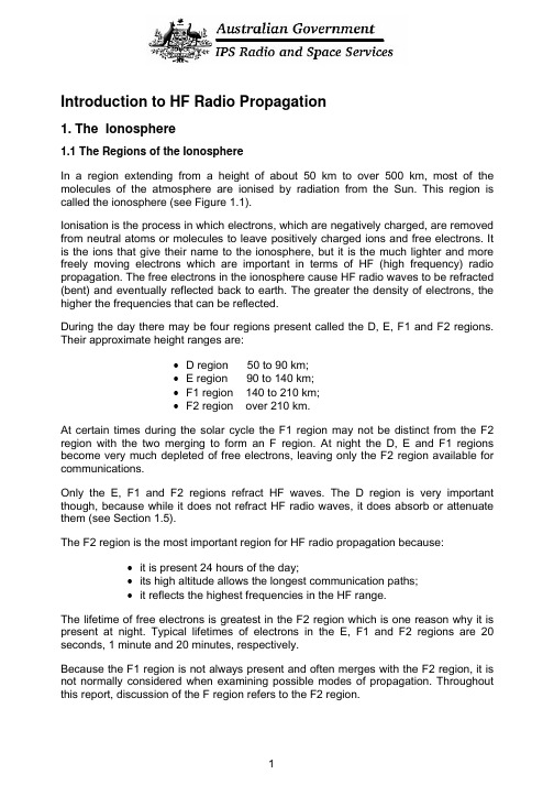
Introduction to HF Radio Propagation1. The Ionosphere1.1 The Regions of the IonosphereIn a region extending from a height of about 50 km to over 500 km, most of the molecules of the atmosphere are ionised by radiation from the Sun. This region is called the ionosphere (see Figure 1.1).Ionisation is the process in which electrons, which are negatively charged, are removed from neutral atoms or molecules to leave positively charged ions and free electrons. It is the ions that give their name to the ionosphere, but it is the much lighter and more freely moving electrons which are important in terms of HF (high frequency) radio propagation. The free electrons in the ionosphere cause HF radio waves to be refracted (bent) and eventually reflected back to earth. The greater the density of electrons, the higher the frequencies that can be reflected.During the day there may be four regions present called the D, E, F1 and F2 regions. Their approximate height ranges are:• D region 50 to 90 km;• E region 90 to 140 km;•F1 region 140 to 210 km;•F2 region over 210 km.At certain times during the solar cycle the F1 region may not be distinct from the F2 region with the two merging to form an F region. At night the D, E and F1 regions become very much depleted of free electrons, leaving only the F2 region available for communications.Only the E, F1 and F2 regions refract HF waves. The D region is very important though, because while it does not refract HF radio waves, it does absorb or attenuate them (see Section 1.5).The F2 region is the most important region for HF radio propagation because:•it is present 24 hours of the day;•its high altitude allows the longest communication paths;•it reflects the highest frequencies in the HF range.The lifetime of free electrons is greatest in the F2 region which is one reason why it is present at night. Typical lifetimes of electrons in the E, F1 and F2 regions are 20 seconds, 1 minute and 20 minutes, respectively.Because the F1 region is not always present and often merges with the F2 region, it is not normally considered when examining possible modes of propagation. Throughout this report, discussion of the F region refers to the F2 region.A l t i t u d e /(k m )Electron density/(electrons/cm 3)Figure 1.1 Day and night structure of the ionosphere.1.2 Production and Loss of ElectronsRadiation from the Sun causes ionisation in the ionosphere. Electrons are produced when solar radiation collides with uncharged atoms and molecules (Figure 1.2). Since this process requires solar radiation, production of electrons only occurs in the daylight hemisphere of the ionosphere.Loss of free-electrons in the ionosphere occurs when a free electron combines with a charged ion to form a neutral particle (Figure 1.3). Loss of electrons occurs continually, both day and night.freeelectronFigure 1.2 Free electron production in the ionosphereunchargedfreeatom(ion)electronFigure 1.3 Loss of free-electrons in the ionosphere.1.3 Observing the IonosphereThe most important feature of the ionosphere in terms of radio communications is its ability to reflect radio waves. However, only those waves within a certain frequency range will be reflected. The range of frequencies reflected depends on a number of factors (see Section 1.4).Various methods have been used to investigate the ionosphere, and the most widely used instrument for this purpose is the ionosonde (Figure 1.4). An ionosonde is a high frequency radar which sends very short pulses of radio energy vertically into the ionosphere. If the radio frequency is not too high, the pulses are reflected back towards the ground. The ionosonde records the time delay between transmission and reception of the pulses over a range of different frequencies.Echoes appear first from the lower E region and subsequently, with greater time delay, from the F1 and F2 regions. At night echoes are returned only from the F region since the E region is not present.IonospherepulseTx delta Rx deltaantenna antennaFigure 1.4 Ionosonde operation.Today, the ionosphere is “sounded” not only by signals sent up at vertical incidence but by oblique sounders which send pulses obliquely into the ionosphere with the transmitter and receiver separated by some distance. This type of sounder can monitor propagation on a particular circuit and observe the various modes being supported by the ionosphere (see Section 2.5). Backscatter ionosondes rely on echoes reflected from the ground and returned to the receiver, which may or may not be at the same site as the transmitter. This type of sounder is used for over-the-horizon radar.1.4 Ionospheric VariationsThe ionosphere is not a stable medium that allows the use of the same frequency throughout the year, or even over 24 hours. The ionosphere varies with the solar cycle, the seasons and during any given day.1.4.1 Variations due to the Solar CycleThe Sun goes through a periodic rise and fall in activity which affects HF communications; solar cycles vary in length from 9 to 14 years. At solar minimum, only the lower frequencies of the HF band will be supported (reflected) by the ionosphere, while at solar maximum the higher frequencies will successfully propagate (Figure 1.5). This is because there is more radiation being emitted from the Sun at solar maximum, producing more electrons in the ionosphere which allows the use of higher frequencies.96Sunspot no.foF2foF1foE Sunspot number CanberraYearF r e q u e n c y /(MH z )0481216889092949800020404080120160Sunspot number foF2foE foF1Figure 1.5 The relationship between solar cycles and maximum frequencies supported by E, F1 and F2 regions. Vertical lines indicate the start of each year. Note also the seasonal variations.There are other consequences of the solar cycle. Around solar maximum there is a greater likelihood of large solar flares occurring. Flares are huge explosions on the Sun which emit radiation that ionises the D region, causing increased absorption of HF waves. Since the D region is present only during the day, only those communication paths which pass through daylight will be affected. The absorption of HF waves travelling via the ionosphere after a flare has occurred is called a short wave fade-out (see Section 3.1). Fade-outs occur instantaneously and affect lower frequencies the most. If it is suspected or confirmed that a fade-out has occurred, it is advisable to try using a higher frequency. The duration of fade-outs can vary between about 10 minutes to several hours, depending on the duration and intensity of the flare.1.4.2 Seasonal VariationsE region frequencies are greater in summer than winter (see Figure 1.5). However, the variation inF region frequencies is more complicated. In both hemispheres, F region noon frequencies generally peak around the equinoxes (March and September). Around solar minimum the summer noon frequencies are, as expected, generally greater than those in winter, but around solar maximum winter frequencies tend to be higher than those in summer. In addition, frequencies around the equinoxes (March and September) are higher than those in summer or winter for both solar maximum and minimum. The observation of winter frequencies often being greater than those in summer is called the seasonal anomaly.1.4.3 Variations with LatitudeFigure 1.6 shows the variations in the E and F region maximum frequencies at mid-day (Day hemisphere) and mid-night (Night hemisphere) from the pole to the equator. During the day, with increasing latitude, the solar radiation strikes the atmosphere more obliquely, so the intensity of radiation and the daily production of free electrons decreases with increasing latitude. In the F region this latitude variation persists throughout the night due to the action of upper atmospheric wind currents from day-lit to night-side hemispheres (see for example, IPS HF Radio Propagation Course and Manual - .au/Products_and_Services/2/2).equatorial 2F E p o l e e q u a t o r mid-latitude trough e q u a t o rNight hemisphere Day hemisphere anomaly H i g h e s t u s a b l e f r e q u e n c y (M H z )121086402040608080604020Geomagnetic latitude (degrees)Figure 1.6 Latitudinal variations.Deviations from the general low to high latitude decrease are also apparent. Daytime F region frequencies peak not at the geomagnetic equator, but 15 to 20° north and south of it. This is called the equatorial anomaly. Also, at night, frequencies reach a minimum around 60° latitude north and south of the geomagnetic equator. This is called the mid-latitude trough. Communicators who require communications near the equator during the day and around 60° latitude at night, should be aware of these characteristics. For example, from Figure 1.6 one can see how rapidly the frequencies can change with latitude near the mid-latitude trough and equatorial anomaly, so a variation in the reflection point near these by a few degrees may lead to a large variation in the frequency supported.1.4.4 Daily VariationsFrequencies are normally higher during the day and lower at night (Figure 1.7). After dawn, solar radiation causes electrons to be produced in the ionosphere and frequencies increase rapidly to a maximum around noon. During the afternoon, frequencies begin falling due to electron loss and with darkness the D, E and F1 regions disappear. Communication during the night is by the F2 (or just F) region only and attenuation is very low. Through the night, maximum frequencies gradually decrease, reaching their minimum just before dawn.6158391202461012141618202224Local time/(hours)F r e q u e n c y /(M H z ) F1F2EFigure 1.7 E, F1 and F2 layer maximum frequencies throughout the day.1.5 Variations in AbsorptionAbsorption was discussed in section 1.4.1 in relation to solar flares. Whilst absorption is extremely high during a solar flare, a certain amount of D region absorption occurs all the time. Absorption in the D region varies with the solar cycle, being greatest around solar maximum. Signal absorption is also greater in summer and during the middle of the day (Figure 1.8). There is a variation in absorption with latitude, with more absorption occurring near the equator and decreasing towards the poles. Lower frequencies are absorbed the most so it is always advisable to use the highestfrequency possible, particularly during the day when absorption is greatest.summer (December 1980)winter (June 1980)V e r t i c a l a b s o r p t i o n /(d B )Time/(LT)5040302010100246812141618202224Figure 1.8 Daily and seasonal variations in absorption at Sydney, 2.2 MHz.Sometimes, high energy protons are ejected from the Sun during large solar flares. These protons move down the Earth’s magnetic field lines, into the polar regions and cause massive ionization of the polar D region leading to increased or total absorption of HF waves. This effect may last for as long as 10 days and is called a Polar Cap Absorption event (PCA) (see Section 3.2).1.6 Sporadic ESporadic E refers to the largely unpredictable formation of regions of very high electron density in the E region. Sporadic E may form at any time during the day or night occurring at altitudes of 90 to 140 km (the E region). It varies greatly in the area it covers (a few km to hundreds) and the time it persists for (minutes to many hours). Sporadic E can have a comparable electron density to the F region which means it can reflect the sort of high frequencies intended for F region communications. Sometimes a sporadic E layer is transparent and allows most of the radio wave to pass through it to the F region, however, at other times the sporadic E layer obscures the F region totally and the signal does not reach the F region and hence the receiver (sporadic E blanketing). If the sporadic E layer is partially transparent, the radio wave is likely to be reflected at times from the F region and at other times from the sporadic E region. This may lead to partial or intermittent transmission of the signal or fading (Figure 1.9).Sporadic E in the low and mid-latitudes occurs mostly during the daytime and early evening, and is more prevalent during the summer months. At high latitudes, sporadic E tends to form at night.Figure 1.9 Sporadic E formation (night or day) may result in communications via the F region being interrupted if the sporadic E electron density is high enough to reflect the wave.1.7 Spread FSpread F occurs when the F region becomes diffuse due to irregularities which scatter the radio wave. The received signal is the superposition of a number of waves reflected from different heights and locations in the ionosphere at slightly different times. At low latitudes, spread F occurs mostly during the night hours and around the equinoxes. At mid-latitudes, spread F is less likely to occur than at low and high latitudes and is more likely to occur at night and in winter. At latitudes greater than about 40°, spread F tends to be a night time phenomenon, appearing mostly around the equinoxes, while around the magnetic poles, spread F is often observed both day and night. At all latitudes there is a tendency for spread F to occur when there is a decrease in F region maximum frequencies (reduced electron density). That is, spread F is often associated with ionospheric storms (see Section 3.3).2. HF Communications2.1 Types of HF PropagationHigh Frequency (3 to 30 MHz) radio signals can propagate to a distant receiver, Figure 2.1, via the:•ground wave: near the ground for short distances, up to 100 km over land and 300 km over sea. Attenuation of the wave depends on antenna height, polarisation, frequency, ground types, terrain and/or sea state;•direct or line-of-sight wave: this wave may interact with the earth-reflected wave depending on terminal separation, frequency and polarisation;•sky wave: reflected by the ionosphere; all distances.2.2 Frequency Limits of Sky WavesNot all HF waves are reflected by the ionosphere; there are upper and lower frequency bounds for communications between two terminals. If the frequency is too high, the wave will pass straight through the ionosphere. If it is too low, the strength of the signal will be very low due to absorption in the D region. The range of usable frequencies will vary:•throughout the day;•with the seasons;•with the solar cycle;•from place to place;The upper limit of frequencies varies mostly with the above factors, while the lower limit also depends on receiver site noise, antenna efficiency, transmitter power, E layer screening (Section 2.6) and absorption by the ionosphere.Figure 2.1 Types of HF propagation.2.3 The Usable Frequency RangeFor any circuit there is a Maximum Usable Frequency (MUF) which is determined by the state of the ionosphere in the vicinity of the reflection points and the length of the circuit. The MUF is reflected from the maximum electron density within a given layer of the ionosphere. Therefore, frequencies higher than the MUF for a particular region will penetrate through that region entirely. During the day it is possible to communicate via both the E and F layers using different frequencies. The highest frequency supported by the E layer is the EMUF, while that supported by the F layer is the FMUF.The F region MUF in particular varies greatly throughout the day, seasonally and with the solar cycle. Historical data collected over many years displays the full range of these variations for a given location. The historical data is averaged and organised to give a MUF for every hour of the day (24 values), for each month of the year. These can also be adjusted for the solar cycle. MUFs are quoted as a statistical range with the “lower decile” (also called the Optimum Working Frequency OWF) working 90% of the time, the “median” MUF working 50% of the time and the “upper decile” MUF working just 10% of the time. IPS predictions usually cover a period of one month, so the OWF for a given hour, should provide successful propagation 90% of the time or 27 days of the that month. The median MUF should provide communications on 15 days of the month and the upper decile MUF on just 3 days of the month. The upper decile MUF is the highest frequency of the range and is most likely to penetrate the ionosphere, thus only working 10% of the time (Figure 2.2).Figure 2.2 Range of usable frequencies. If the frequency, f, is close to the ALF then the wave may suffer absorption in the D region. If the frequency is above the EMUF then propagation is via the F region. Above the FMUF the wave is likely to penetratethe ionosphere.The statistical MUFS described above correspond to “quiet background” conditions. With short-term variations in solar activity however, away from quiet background levels, usable frequencies change. This needs to be reflected in MUF predictions and one ofthe roles of the Australian Space Forecast Centre (ASFC) at IPS is to modify the historical MUFS to reflect the real-time observed space-weather conditions. Sophisticated techniques have been developed at IPS over many years to combine the effects of observed space-weather conditions with historically averaged data to provide detailed and accurate predictions of ionospheric conditions.D region absorption of HF radio waves increases rapidly with decreasing frequency. The D region thus places a lower limit on the frequencies which can be used for ionospheric propagation. This limit is called the Absorption Limiting Frequency (ALF). The ALF is significant only for circuits with reflection points in the sunlit hemisphere. At night, the ALF falls to zero, allowing frequencies which are not usable during the day to successfully propagate.2.4 Hop LengthsThe hop length is the ground distance covered by a radio signal after it has been reflected once from the ionosphere and returned to Earth (Figure 2.3). The maximumhop length is set by the height of the ionosphere and the curvature of the Earth. For Eand F region heights of 100 km and 300 km, the maximum hop lengths are about 1800km and 3200 km, respectively (corresponding to an elevation angle of around 4°).Distances greater than these will require more than one hop. For example, a distance of 6100 km will require a minimum of 4 hops by the E region and 2 hops via the F region. More hops are required again with larger antenna elevation angles.Figure 2.3 Hop lengths based upon an antenna elevation angle of 4° and heights for the E and F layers of 100 km and 300 km, respectively.2.5 Propagation ModesThere are many paths by which a sky wave may travel from a transmitter to a receiver. The mode reflected by a particular layer which requires the least number of hops between the transmitter and receiver is called the first order mode. The mode that requires one extra hop is called the second order mode, and so on. For a circuit with a path length of 5000 km, the first order F mode has two hops (2F), while the second order F mode has three hops (3F). The first order E mode has the same number of hops as the first order F mode. If this results in a hop length of greater than 2050 km, which corresponds to an elevation angle of 0°, then the E mode is not possible.Simple modes are those propagated by one region, say the F region. IPS predictions are made only for these simple modes (Figure 2.4). More complicated modes consisting of combinations of reflections from the E and F regions, ducting and chordal modes are also possible (Figure 2.5).Figure 2.4 Examples of simple propagation modes.Chordal modes and ducting involve a number of reflections/refractions from the ionosphere without intermediate reflections from the Earth. There is a tendency to think of the regions of the ionosphere as being smooth, however, the ionosphere undulates and moves, with waves passing through it which affects the refraction of radio signals. When ionospheric layers tilt chordal and ducted modes may occur. Ionospheric tilting is more likely near the equatorial anomaly, the mid-latitude trough and in the sunrise and sunset sectors of the globe. When these types of modes occur, signals can be strong since the wave spends less time traversing the D region or being attenuated by ground reflections.Figure 2.5 Complex propagation modes.Because of the high electron density of the daytime ionosphere around 15° from the magnetic equator (near the equatorial anomaly), trans-equatorial paths can propagate on very high frequencies. Any tilting of the ionosphere in this region may result in chordal modes (see Figure 2.5) which produce good signal strength over very long distances.Ducting may also result if tilting occurs and the wave becomes trapped between reflecting regions of the ionosphere (see Figure 2.5). This is most likely to occur in the equatorial ionosphere, near the auroral zone and mid-latitude trough. Disturbances to the ionosphere, such as travelling ionospheric disturbances (see Section 2.9), may also initiate ducting and chordal modes.2.6 E Layer ScreeningFor daytime communications via the F region, the lowest usable frequency via the one hop F mode (1F) is dependent upon the presence of the E region. If the operating frequency is below the two hop EMUF, then the signal will propagate via the 2E mode rather than the 1F mode (Figure 2.6). This is also because the antenna elevation angles of the 1F and 2E modes are similar.Figure 2.6 E layer screening occurs if communications are intended by the 1F mode but the operating frequency is close to or below the EMUF for the 2E mode. Note that the 2 hop E mode travels twice as many times through the D region.A sporadic E layer may also screen a HF wave from the F region. Sometimes sporadic E can be quite transparent, allowing most of the wave to pass through it. At other times it will partially screen the F region leading to a weak or fading signal, while at other times sporadic E can totally obscure the F region with the result that the signal does not arrive at the receiver (Figure 1.9).2.7 Frequency, Range and Elevation AngleFor HF propagation path, there are three dependent variables:• frequency;•range or path length;•antenna elevation angle.The diagrams below illustrate the possible changes to the ray paths when each of these is fixed in turn.Figure 2.7: Elevation angle fixed:•As the frequency is increased toward the MUF, the wave is reflected higher in the ionosphere and the range increases; paths 1 and 2•Exactly at the MUF, the maximum range is reached; path 3•Above the MUF, the wave penetrates the ionosphere; path 44. frequency too highFigure 2.7 Elevation angle fixed.Figure 2.8: Path length fixed (point-to-point circuit):•As the frequency is increased towards the MUF, the wave is reflected from higher in the ionosphere. To maintain a circuit of fixed length, the elevation angle must therefore be increased (paths 1 and 2)• At the MUF, the critical elevation angle is reached (path 3). The critical elevation angle is the highest elevation angle for a particular frequency.•Above the MUF, the ray penetrates the ionosphere (path 4).Figure 2.8 Path length fixed.Figure 2.9: Frequency fixed:•At low elevation angles the path length is greatest (path 1);•As the elevation angle is increased, the path length decreases and the ray is reflected from higher in the ionosphere (paths 2 and 3);•If the elevation angle is increased beyond the critical elevation angle for that frequency then the wave penetrates the ionosphere and there is an area around the transmitter within which no sky wave communications can be received (path 4). To communicate within this so called “skip zone”, the frequency must be lowered.•If a signal of a certain frequency is reflected when vertically incident on the ionosphere, then there is no skip zone. The vertically incident maximum frequency is referred to as f0F2 and is a key ionospheric parameter.Figure 2.9 Frequency fixed.2.8 Skip ZonesSkip zones can often be used to advantage if it is desired that communications are not heard by a particular receiver. Selecting a frequency which puts a receiver in the skip zone and out of reach of the ground wave makes it unlikely that it will receive the communications. However, factors such as sidescatter, where reflection from the Earth outside the skip zone results in the wave transmitting into the skip zone may affect the reliability of this.Skip zones vary in size during the day, with the seasons, and with solar activity. During the day, solar maximum and around the equinoxes, skip zones generally are smaller in area. The ionosphere during these times has increased electron density and so is able to support higher frequencies.2.9 FadingMultipath fading results when a number of modes propagate from transmitter to receiver, which have variations in phase and amplitude. See for example, Figure 2.4. The signal travels by a number of paths simultaneously which may interfere at the receiver, causing fading.Disturbances known as Travelling Ionospheric Disturbances (TID), may cause a region to be tilted, resulting in the signal being focussed or defocused (Figure 2.10). Fading periods of the order of 10 minutes or more can be associated with these structures. TIDs travel horizontally at 5 to 10 km/minute with a well defined direction of travel andaffect higher frequencies first. Some originate in auroral zones following an event on the Sun and these may travel large distances. Others originate in lower atmospheric weather disturbances. TIDs may cause variations in phase, amplitude, polarisation and angle of arrival of a radio wave.Polarisation fading results from changes to the polarisation of the wave along the propagation path with the receiving antenna being unable to receive parts of the signal. This type of fading can last for a fraction of a second to a few seconds.Skip fading often occurs around sunrise and sunset when the ionosphere is at its most unstable. If the operating frequency is close to the MUF and the receiving antenna is positioned close to the boundary of the skip zone then signal will fade in and out with fluctuations in the ionosphere.Figure 2.10 Focussing and defocussing effects caused by travelling ionospheric disturbances (TIDs).2.10 NoiseRadio noise arises from internal and external origins. Internal or thermal noise is generated in the receiving system and is usually neglig ible for a good quality receiver when compared to external sources of noise. External radio noise originates from natural (atmospheric and galactic) and man-made (environmental) sources. Atmospheric noise, which is caused by thunderstorms, is normally the major contributor to radio noise in the HF band and will especially degrade circuits passing through the day-night interface. Atmospheric noise is greatest in the equatorial regions and decreases with increasing latitude. Its effect is also greater on lower frequencies so isusually more of a problem around solar minimum and at night when lower frequencies are needed.Galactic noise arises from our galaxy. Since only the highest frequencies will pass through the ionosphere (from above) galactic noise only effects high frequencies.Man-made noise results from any large currents and voltages such as ignition systems, neon signs, electrical cables, power transmission lines and welding machines. This type of noise depends on the technology used by the society and its population. Interference may be intentional (jamming), due to propagation conditions or the result of others operating on the same frequency.Man-made noise tends to be vertically polarised, so selecting a horizontally polarised antenna may help in reducing man-made noise. Using a narrower bandwidth, or a directional receiving antenna (with a lobe in the direction of the transmitting source and a null in the direction of the unwanted noise source), will also aid in reducing the effects of noise. Selecting a site with a low noise level and determining the major noise sources are important factors in establishing a successful communications system.2.11 VHF and 27 MHz PropagationVHF and 27 MHz are used for line-of-sight or direct wave communication, for example, ship-to-ship or ship-to-shore. The frequency bands are divided into channels and one channel is usually as good as the next. This is in contrast to medium frequency (MF: 300 kHz to 3 MHz) and HF where the choice of a frequency channel may be crucial for good communications.Because VHF and 27 MHz operate mainly by line-of-sight, it is important to mount the antenna as high as possible and free from obstructions. Shore stations are usually on the tops of hills to provide maximum range, but even the highest hills do not provide coverage beyond about 45 nautical miles (80 km), because of the Earth’s curvature. Antennas for VHF and 27 MHz should usually concentrate radiation at low angles (towards the horizon) as except when communicating with aircraft, radiation directed at high angles will pass over the receiving antenna. VHF and 27 MHz do not usually suffer from atmospheric noise except during severe electrical storms. Interference mainly results from many users wishing to use the limited number of channels, and this can bea significant problem in densely populated areas.27 MHz and the lower frequencies in the VHF band can, at times, propagate over large distances, well beyond the normal line-of-sight limitations. There are three ways that this can take place:•around solar maximum and during the day, the ionospheric F region will often support long range sky wave communications on 27 MHz and above;•sporadic E layers can often support 27 MHz and lower frequency VHF propagation over circuits of about 500 to 1000 nautical miles (1000 to 2000 km) in length. This kind of propagation is most likely to occur at mid-latitudes, during the daytime in summer;•27 MHz and VHF can also propagate by means of temperature inversions (ducting) at altitudes of a few kilometres. Under these conditions, the waves are gradually。
液偶说明书-中文
4 运输和储存 .................................................................................................错误!未定义书签。
- 1、下载文档前请自行甄别文档内容的完整性,平台不提供额外的编辑、内容补充、找答案等附加服务。
- 2、"仅部分预览"的文档,不可在线预览部分如存在完整性等问题,可反馈申请退款(可完整预览的文档不适用该条件!)。
- 3、如文档侵犯您的权益,请联系客服反馈,我们会尽快为您处理(人工客服工作时间:9:00-18:30)。
FdYf_1 Lgmflaf_ DaklYf[] :93=ee
72u83= 673< 87 6 8 : 7
7=3:
9< :93= ;<3=
.Sgh na]o/
799
6; ; 9
8
;
9
元器件交易网
:?>7692 16829=6:9={ A6<694 16.4<.8 .91 ;0 /:.<1 7.B:?>
s WaYe]f Hgf_^Y Ed][ljgY[gmkla[ Cg31 Kl\3 Add ja_`lk g^ Hgf_^Y Yj] j]k]jn]\3
79:
Q]eYjc? If [Yk] g^ fg lgd]jYf[] k`gof af gmldaf] \ae]fkagf? gmldaf] \ae]fkagf W6ee1 lgd]jYf[] k`gmd\ Z] t537ee@ gmldaf] \ae]fkagf Y6ee Yf\ W:ee1 lgd]jYf[] k`gmd\ Z] t538ee@ gmldaf] \ae]fkagf Y:ee1 lgd]jYf[] k`gmd\ Z] t539ee3
0:67 1.>.
MgeafYd UgdlY_] UDC ; > 67 79 9= 675 MgeafYd UgdlY_] UAC ; :55L .Yl :55UDC/ 7555UAC 6eaf 6555UAC 6eaf DC lqh]? 7:ek eYp3 DC lqh]? 7:ek eYp3 ;5J eYp3 655e4k7 .65_/ 65Hr lg ::Hr 635ee DA 275 lg 95 PC Ahhjgp3 =:_ Dmkl hjgl][l]\ ?7z0?< HF>9F267 >=, QH1 95 67 79 9= 675 795 7<< Oa[c2mh UgdlY_] UDC 93:5 ;3<: >355 6=35 8;35 >535 Oa[c2mh UgdlY_] UAC :36 6537 7539 953= 657 759 759 Djgh2gml UgdlY_] UDC 53; 53> 637 739 93= 6735 LYp3 AddgoYZd] UgdlY_] UDC ;3; >3> 6837 7;39 :73= 687 Cgad Q]kaklYf[] 6<3: p .6 65,/ 95 p .6 65,/ <5 p .6 65,/ 7=5 p .6 65,/ 6675 p .6 65,/ <555 p .6 65,/ Cgad Q]kaklYf[] 93= p .6 65,/ 6> p .6 65,/ << p .6 65,/ 7=5 p .6 65,/ 7555 p .6 65,/ <7:5 p .6 65,/ 66555 p .6 65,/
265
A
79
6
.WWW/
0MLQCDQ COOCLHFKFLQ
}|- 6 Fgje A }}- 6 Fgje B .- AC 1- DC }~- 6 Fgje C }*- 6A06B
0MIJ SMJQCHF GMOK 0MIJ SMJQCHF 8MRLQILH
.0- ; lg 7<<UAC 10- ; lg 675 UDC }- FdYf_1 Lgmflaf_ DaklYf[] :93=ee3 \aYe]l]j u83=ee ~- FdYf_1 Lgmflaf_ DaklYf[] ;;3<ee3 \aYe]l]j u93=ee 9IJ- L]lYd BjY[c]l
=.32>B .;;<:@.7 <.>694=
HF>9F265 67FKA1;5KQA =FKA19=KQA 7:5UAC <FKA197KQA 7<<UAC 7:A 7<<UAC 69FKA1=9KQA =FKA19=KQA <FKA197KQA 7:A 67FKA1;5KQA =FKA19=KQA <FKA197KQA 7:A 67:UAC 7:5UAC 7<<UAC 7<<UAC 675UAC 7:5UAC 7<<UAC 7<<UAC
Nmldaf] Dae]fkagfk
FdYf_1 Lgmflaf_ DaklYf[] ;;3<ee
ห้องสมุดไป่ตู้
Tfal? ee
72u93= 6:3= 87 6 8 : ; 7 9
7=3:
9< ;;3< <;37
.Sgh na]o/
S]jeafYdk lqh]
u63> W 536: ;39 0535: 2 536: >3= = 53= 05359 2 5357
HNMGFA QEKAX IRN>556VIRN4SR6;>9> VIRN69556 VNHRAR6=556 CEQSIFIED
755< Q]n3 7355
798
元器件交易网
:<12<694 693:<8.>6:9
HF>9F
>TNF 6/
HF>9F
>955 .Nd\ lqh]/
0RPQMKFO PNFDICJ DMEF 7/
Nfdq ^gj kh][aYd j]imaj]e]flk1 ]3_3 .:::/ klYf\k ^gj QgHR [gehdaYfl
9MQFP- 6/ V] `Yn] fgo _jY\mYddq mh\Yl]\ gmj gj\]jaf_ af^gjeYlagf3 V] km__]kl f]o lqh] k`gmd\ Z] k]d][l]\3 I^ f][]kkYjq1 gd\ lqh] [Yf Z] c]hl ^gj kge] h]jag\ ^gj l`] gd\ [mklge]jk3 7/ HF>9F ak Yf ]fnajgfe]flYd ^ja]f\dq hjg\m[l3 Od]Yk] eYjc Y kh][aYd [g\] .:::/ o`]f gj\]jaf_3
0:9>.0> 1.>.
CgflY[l YjjYf_]e]fl CgflY[l j]kaklYf[] CgflY[l eYl]jaYd CgflY[l jYlaf_ .Q]k3dgY\/ LYp3 koal[`af_ ngdlY_] LYp3 koal[`af_ [mjj]fl LYp3 koal[`af_ hgo]j L][`Yfa[Yd ]f\mjYf[] Ed][lja[Yd ]f\mjYf[] 6A1 6B1 6C1 6A 0 6B 755e .Yl 6A 79UDC/ A_C] 6=A 7<<UAC 7<<UAC 7:A ;>7:UA 6 p 65; NOR 6 p 65: NOR
0:67
Cgad hgo]j DC lqh]? 739V@ AC lqh]? 935UA
HF>9F268
9MQFP- Nfdq kge] lqha[Yd jYlaf_k Yj] dakl]\ YZgn]3 I^ egj] \]lYadk Yj] j]imaj]\1 hd]Yk] [gflY[l mk3
9
Vajaf_ DaY_jYe
.Sgh na]o/
6 Fgje A
6 7
6 Fgje B
6 : 6
6 Fgje C
: 7 6
6A06B
: 7
8
9
8
;
8
;
9
8
;
9
Dak[dYae]j
S`ak \YlYk`]]l ak ^gj l`] [mklge]jkv j]^]j]f[]3 Add l`] kh][a^a[Ylagfk Yj] kmZb][l lg [`Yf_] oal`gml fgla[]3 V] [gmd\ fgl ]nYdmYl] Ydd l`] h]j^gjeYf[] Yf\ Ydd l`] hYjYe]l]jk ^gj ]n]jq hgkkaZd] Yhhda[Ylagf3 S`mk l`] mk]j k`gmd\ Z] af Y ja_`l hgkalagf lg [`ggk] l`] kmalYZd] hjg\m[l ^gj l`]aj gof Yhhda[Ylagf3 I^ l`]j] ak Yfq im]jq1 hd]Yk] [gflY[l Hgf_^Y ^gj l`] l][`fa[Yd k]jna[]3 Hgo]n]j1 al ak l`] mk]jvk j]khgfkaZadalq lg \]l]jeaf] o`a[` hjg\m[l k`gmd\ Z] mk]\ gfdq3
:?>7692 16829=6:9={ A6<694 16.4<.8 .91 ;0 /:.<1 7.B:?>
Tfal? ee
Nmldaf] Dae]fkagfk
L]lYd BjY[c]l
9< 72u938 6 : 7 8>3< 87 :93= ;;3< << >3:
92u83= 9;
63:
7=
.Sgh na]o/
元器件交易网
53,+3 .>955/
5645 ;:A2< <27.B
3FCQROFP
X 7:A koal[`af_ [YhYZadalq X 7cU \a]d][lja[ klj]f_l` Fad] Mg3?E689:6< .Z]lo]]f [gad Yf\ [gflY[lk/ X OYf]d egmfl1 nYjagmk l]jeafYd lqh]k X Efnajgfe]flYd ^ja]f\dq hjg\m[l .QgHR [gehdaYfl/ X Nmldaf] Dae]fkagfk? .9<35 p 8735 p 7=3:/ ee Fad] Mg3?CPC5855655=;9>