RJ-1.83.3DH中文资料
产品名称:3 8英寸NPTx3 8英寸OD球值包装说明书

INSTALLATION MANUALIntroductionWhat’s in the BoxBundled package∙12VDC power adapter∙Outlet ball valve (3/8” NPT x 3/8” OD Ball Valve)∙Overflow hose barb (½” NPT hose barb)∙Toggle anchor (x3)∙3/16” x 2 ½” bolts (x3)∙Disc screen∙Disc nozzle (clear)∙Disc diverterWall Mount Assembled Unit(Configured for bottle use. See instructions below for disc use)∙Reservoir∙Top∙Cover∙Electronics package∙Inlet assemblyAdditional Items Needed∙I nlet tubing (3/8” OD)∙O utlet tubing (3/8” OD)∙O verflow tubing (1/2” ID)∙M asonry screws 3/16” x 2 ½” (if installing in solid wall) Tools Needed∙Drill - 1/2” bit (if using supplied toggle anchors) OR5/32” masonry drill bit (for solid wall)∙Philips screwdriver∙Level∙Tape measure∙PTFE Tape∙14 mm or 9/16” socket and driver w/ extension (for disc conversion)handling procedures.∙Always wear protective clothing and eyewear when working with solid dissolving equipment and chemicals.∙Regularly inspect all tubing for cracking or deterioration. Replace as needed.∙Do not modify supplied power adapter and/or cord.∙If supplied power adapter is damaged or frayed, contact manufacturer or local representative.∙Always shut off water supply before removing cover.∙Disconnect power adapter from supply source before performing any maintenance or service.minimize exposure to the elements.∙All installations should be done in accordance with local plumbing codes and requirements. ∙Ensure that dissolver is installed on a structurally sound surface that is able to hold up to 50 lbs.∙Take proper precautions if installing where water hammer is a concern.∙Dimensions –10” w x 23” h x 13.6” d (not including solution outlet valve)Select location for installation.1.Reference FIGURE A on page 6 for Ultra-S dimensions.2.NOTE: Be sure to allow extra room above and below the Ultra-S forproduct loading and tubing hookups.Locating the wall mount.1.Reference FIGURE B on page 6 for mount dimensions and holelocations.ing a level, draw a vertical center line on the installation location(see below for installing multiple mounts)3.Line mounting holes on mount with the vertical line4.While holding mount in place, mark the 3 hole locations5.Remove the mount from wallInstalling the mount1.Installing in hollow wall (i.e. drywall not mounted on stud)ing a ½” drill bit, drill out the wall at the marked locations in previous step.b.Install toggle anchors into holes.i.Hold metal channel flat alongside plastic straps and slide channel through hole.ii.Hold ends of straps between thumb and forefinger and pull toward you until channel rests flush behind wall. Slide plastic cap along straps with other hand until flange of cap is flushwith wall.iii.Place thumb between straps at wall. Push thumb side to side, snapping off straps level with flange of cap.2.Installing on solid wall (i.e. masonry)ing a 5/32” masonry drill bit, dr ill pilot holes into solid wall.b.Place mount over holes with flat side against the wall.c. Insert masonry screws (not supplied) though mount into holes and tighten.Hanging the Ultra-S1.Lift assembled Ultra-S up and slide down onto mount, allowing to mount to fit in the recessedback portion of the reservoir.2.Ensure unit is level and plumb.Connecting water supply1.Connect water supply via 3/8” OD tubing to the inlet assembly by inserting it into the ball valvequick connect. (NOTE: It is recommended to have an inline shutoff valve located upstream of the Ultra-S)2.Ensure tubing is completely seated in the fitting.Connecting solution outleting PTFE tape, wrap the threads of the outlet ball valve.2.Screw the outlet ball valve into the 3/8” NPT port located on the bottom of the reservoir. (NOTE:be sure to not cross-thread fitting when installing)3.Insert 3/8” OD tubing into the outlet ball valve.4.Ensure tubing is completely seated in the fitting.5.Connect the other end of the tubing to the chemical pump (or equivalent).Connecting overflow porting PTFE tape, wrap the threads of the overflow hose barb.2.Screw the overflow hose barb into the ½” NPT port located on the bottom of the reservoir. (NOTE:be sure to not cross-thread fitting when installing)3.Slide ½” ID tubing onto the hose barb.4.Route tubing to drain.Inserting product1.Bottlesa.Remove the cover from the Ultra-S and set asideb.Invert bottle and gently place into product receptacle.i.NOTE: Seals may need to be removed from product before inserting.c.Re-install cover onto Ultra-S2.Discsa.Remove the cover from the Ultra-S and set asideing a 14mm socket and driver w/ extension, remove the bottle nozzle installed in the Ultra-Sc.Install disc nozzle. Do not over-tighten.d.Install disc screen with the screen side up.e.Remove product disc from packaging and gently slide into product receptacle.i.NOTE: Up to 4 discs can be installed at a time.f.Place the disc cap on top of the installed discs.g.Re-install cover onto Ultra-S.Turning on water1.Slowly open the ball valve located on the inlet assembly.2.Open any upstream shutoff valves.Connecting power1.Only use the supplied power adapter.2.Plug power supply into a GFCI 120V outlet that is always hot.3.Connect barrel connector to electronics package.4.The Ultra-S will run through a series of checks when first powered on. This process takes about 20-30seconds. When the Ultra-S is first powered on, if the reservoir is empty or mostly empty, the solenoid will energize for 8 additional seconds to check the operation of the system.INSTALLING MULTIPLE UNITSWhen mounting units next to each other, mounts should be instal led at least 10 ½” apart on center from each other.The Ultra-S is equipped with a green and a red LED located on the side of the electronics box. The lights will flash in a certain pattern (see table below) to show the status or error. Whenever the green light is on or flashing, the Ultra-S is still functional. If the green light is not on, then the Ultra-S is in a permanent error state and will need to be reset by unplugging the power and plugging it back in.FIGURE AFIGURE B (DIMENSIONS ARE IN INCHES)DISCLAIMERThe enduroTEQ Ultra-S product is provided without any guarantees or warranties, except the Limited Warranty on Parts set forth below. There is no warranty of merchantability, no warranty of fitness for a particular purpose, no warranty of title, and no guarantee of non-infrin gement of third party rights. Use of the product by the user is solely at the user’s risk.LIMITED WARRANTYAPTech Group, Inc., will provide a one-year Limited Warranty on parts for the enduroTEQ Ultra-S from the receipted date of purchase, provided the enduroTEQ Ultra-S has been used by the customer only for distribution of APTech’s supported products. Upon proper submission of a claim, in writing, for parts or materials, to APTech Group, Inc., accompanied by a receipt for the purchase, dated within a one-year period from the date of the original purchase, new replacement parts will be provided free of charge, subject to shipping and handling costs.Who we areAPTech Group manufactures solid, concentrated water treatment products for boilers, cooling towers and other water systems. APTech has developed a product to be easier, safer and more environmentallyfriendly than traditional water treatment products.Contact Us11411 Williamson RoadCincinnati, OH 45241Phone: 866.489.9831Email:*********************Web: 。
BP9833D中文规格书

LED 平板灯 LED 日光灯
LED 吸顶灯 其它 LED 照明
引出端排列
GND 1 ROVP 2
NC 3 VCC 4
DIP-8
8 CS 7 CS 6 DRAIN 5 DRAIN
引出端功能
序号
符号
1
GND
2
ROVP
3
NC
4
VCC
功能描述 地
开路保护电压调节端 空 电源
序号 5 6 7 8
符号 DRAIN
CS
功能描述 内置高压功率管漏极
电流采样端
V.1.1
第1 页 共9 页
电路方框图
CSC8933兼容BP9833D
最大额定值
项目 电源脚最大电流 内部高压 MOS 管漏源峰 值电压 电流采样端电压 开路保护电压调节端
功耗
热阻
贮存温度 工作结温 ESD
符号 Icc_max
DRAIN
CS
其中,f 为系统工作频率。CSC8933 的系统工作频率和输入电压成正比关系,设置 CSC8933 系统工作 频率时,选择在输入电压最低时设置系统的最低工作频率,而当输入电压最高时,系统的工作频率 也最高。 CSC8933 设置了系统的最小退磁时间和最大退磁时间,分别为 4.5us 和 240us。由 TOFF 的
过压保护电阻设置
开路保护电压可以通过 ROVP 引脚电阻来设置,ROVP 引脚电压为 0.5V。 当 LED 开路时,输出 电压逐渐上升,退磁时间变短。因此可以根据需要设定的开路保护电压,来计算退磁时间 TOVP。
VCS 是 CS 关断阈值(400mV) VOVP 是需要设定的过压保护点
TOVP
≈
L ×VCS RCS ×VOVP
583815-3资料
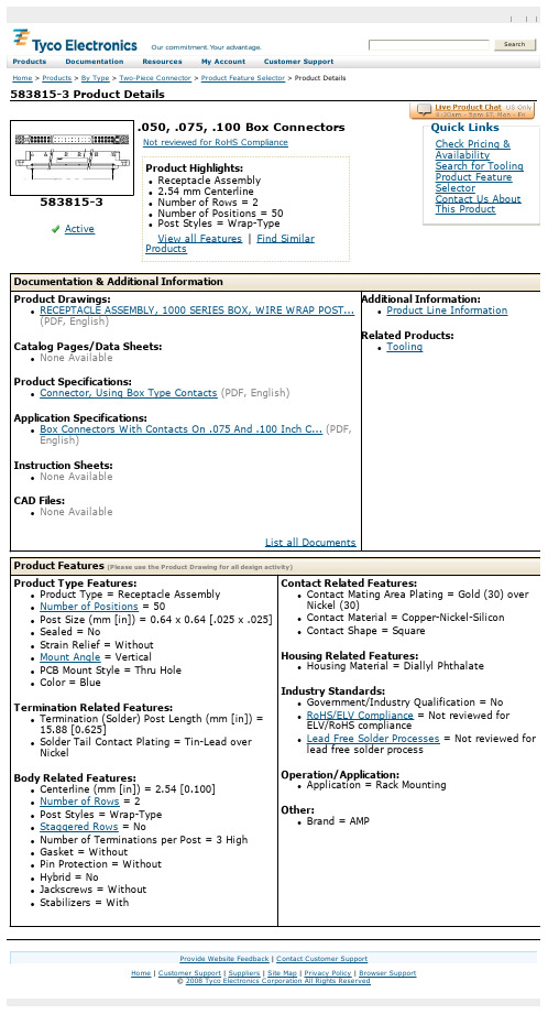
583815-3 Product DetailsHome | Customer Support | Suppliers | Site Map | Privacy Policy | Browser Support© 2008 Tyco Electronics Corporation All Rights Reserved Searc hProducts Documentation Resources My Account Customer Support Home > Products > By Type > Two-Piece Connector > Product Feature Selector > Product Details583815-3Active .050, .075, .100 Box ConnectorsNot reviewed for RoHS ComplianceProduct Highlights:l Receptacle Assemblyl 2.54 mm Centerlinel Number of Rows = 2l Number of Positions = 50l Post Styles = Wrap-TypeView all Features | Find SimilarProductsCheck Pricing &AvailabilitySearch for ToolingProduct FeatureSelectorContact Us AboutThis ProductQuick LinksDocumentation & Additional InformationProduct Drawings:l RECEPTACLE ASSEMBLY, 1000 SERIES BOX, WIRE WRAP POST...(PDF, English)Catalog Pages/Data Sheets:l None AvailableProduct Specifications:l Connector, Using Box Type Contacts(PDF, English)Application Specifications:l Box Connectors With Contacts On .075 And .100 Inch C...(PDF, English)Instruction Sheets:l None AvailableCAD Files:l None AvailableList all Documents Additional Information:l Product Line InformationRelated Products:l ToolingProduct Features (Please use the Product Drawing for all design activity)Product Type Features:l Product Type = Receptacle Assemblyl Number of Positions = 50l Post Size (mm [in]) = 0.64 x 0.64 [.025 x .025] l Sealed = Nol Strain Relief = Withoutl Mount Angle = Verticall PCB Mount Style = Thru Holel Color = BlueTermination Related Features:l Termination (Solder) Post Length (mm [in]) =15.88 [0.625]l Solder Tail Contact Plating = Tin-Lead overNickelBody Related Features:l Centerline (mm [in]) = 2.54 [0.100]l Number of Rows = 2l Post Styles = Wrap-Typel Staggered Rows = Nol Number of Terminations per Post = 3 Highl Gasket = Withoutl Pin Protection = Withoutl Hybrid = Nol Jackscrews = Withoutl Stabilizers = With Contact Related Features:l Contact Mating Area Plating = Gold (30) overNickel (30)l Contact Material = Copper-Nickel-Siliconl Contact Shape = SquareHousing Related Features:l Housing Material = Diallyl PhthalateIndustry Standards:l Government/Industry Qualification = Nol RoHS/ELV Compliance = Not reviewed forELV/RoHS compliancel Lead Free Solder Processes = Not reviewed forlead free solder processOperation/Application:l Application = Rack MountingOther:l Brand = AMPProvide Website Feedback | Contact Customer Support。
Glenair高速八轴接触器产品说明书

®OCTAXIAL CONTACTSEthernet, SuperSpeed USB, HDMI, DisplayPort, SATAFEBRUARY 2018For Series 23 SuperNine ®, Series 80 Mighty Mouse, Series 28HiPer-D ®, Series 791, Series 792, ARINC 600 and EPXB Connectors®Glenair, Inc.1211 Air WayGlendale, CA 91201-2497818-247-6000*****************High-speed octaxial contacts for Ethernet, SuperSpeed USB and multi-gigabit datalinksHIGH-SPEED CONTACT TECHNOLOGYEl Ochito ® WhiteEl Ochito ® BlueEl Ochito ® Red10G Ethernet 1000BASE-T 10GBASE-TSuperSpeed USB 3.0HDMI SATA DisplayPortHigh speed, harsh environment El Ochito®octaxial contacts save size and weight. Suitable for aircraft avionics, weapons systems, satellites, radars,communications equipment and other aerospace/defense gear,El Ochito® contacts are optimized for 10G Ethernet, SuperSpeed USB and other multi-gigabit datalink protocols including HDMI, DisplayPort and SATA.El Ochito Type II Contacts24-26 AWG, Serviceable, Threaded Wire Shield Termination, Integral Contact Release Sleeve© 2018 Glenair, Inc • 1211 Air Way, Glendale, CA 91201 • 818-247-6000 • • U.S. CAGE code 06324 • El Ochito ® Octaxial ContactsDimensions in Inches (millimeters) are subject to change without notice.1000BASE-T, 10GBASE-TSuperSpeed USBHDMI, DisplayPort, SATAData Pair IsolatorData Pair IsolatorFront InsulatorFront InsulatorOuter BodyOuter BodyAlignment KeyAlignment KeyContact Organizer InsulatorContact Organizer InsulatorSocket ContactsPin Contacts SleeveDielectric SleeveType I Pin Contact Type I Socket ContactData Pair Isolator Data Pair IsolatorFront InsulatorFront InsulatorOuter BodyOuter BodyAlignment KeyAlignment KeyContact Release SleeveContact Release SleeveContact Organizer InsulatorContact Organizer InsulatorSocket ContactsPin ContactsRetainer NutRetainer NutO-ringO-ringHeatshrink TubeHeatshrink TubeInner FerruleInner FerruleType II Socket Contact10GBASE-T El Ochito®SuperSpeed USBSATAEl Ochito®Red859-134(GS206)© 2018 Glenair, Inc • 1211 Air Way, Glendale, CA 91201 • 818-247-6000 • • U.S. CAGE code 06324 • El Ochito®Octaxial Contacts© 2018 Glenair, Inc • 1211 Air Way, Glendale, CA 91201 • 818-247-6000 • • U.S. CAGE code 06324 • El Ochito ® Octaxial Contacts Dimensions in Inches (millimeters) are subject to change without notice.5DimensionsEl Ochito ® Type I Pin Contact 858-003, 858-016, 858-028, and 858-030.920(23.37) MAXØ .276/.271(7.01/6.88).060 (1.52).033/.029 (0.84/0.74).305/.295(7.75/7.49)858-003, 858-028-01: .231 (5.87) HEX858-016, 858-028-02, 858-030: .265 (6.73) ROUNDØ .316/.313(8.03/7.95)Ø .219/.217(5.56/5.51)POLARIZATIONKEYPIN NO. DESIGNATION (NOT MARKED ONPART)CABLE (REF)12345678 SHIELD CRIMP FERRULEEl Ochito ® Type II Pin Contact 858-0051.625 (41.28) MAX Ø .316/.313(8.03/7.95)Ø .219/.217(5.56/5.51)CABLE (REF)HEATSHRINKTUBING.033/.029 (0.84/0.74).305/.295(7.75/7.49).060 (1.52)POLARIZATIONKEYPIN NO. DESIGNATION (NOT MARKED ON PART)12345678.313 (7.95) FLATS.320 (8.13) HEXINTEGRAL RELEASE SLEEVESHIELDRETAINER NUTEl Ochito ® Type II Socket Contact 858-0061.950 (49.53) MAX Ø .316/.313(8.03/7.95)CABLE (REF)HEATSHRINKTUBING.033/.029 (0.84/0.74).060 (1.52)POLARIZATIONKEY PIN NO. DESIGNATION (NOT MARKED ON PART)12345678.320 (8.13) HEXINTEGRAL RELEASE SLEEVE.313 (7.95) FLATSØ .288/.284(7.32/7.21).631/.625 (16.02/15.88)SHIELDRETAINER NUTEl Ochito ® Type I Socket Contact 858-004, 858-017, 858-029, and 858-031.770(19.56)MAX .033/.029(0.84/0.74).631/.625(16.02/15.88)POLARIZATIONKEYØ .288/.284(7.32/7.21)Ø .316/.313(8.03/7.95)Ø .276/.271(7.01/6.88)SHIELD CRIMP FERRULE 858-004, 858-029-01: .231 (5.87) HEX858-017, 858-029-02, 858-031: .265 (6.73) ROUNDCABLE (REF).060 (1.52)PIN NO. DESIGNATION (NOT MARKED ONPART)12345678®Octaxial Contacts6© 2018 Glenair, Inc • 1211 Air Way, Glendale, CA 91201 • 818-247-6000 • • U.S. CAGE code 06324 • El Ochito ® Octaxial ContactsDimensions in Inches (millimeters) are subject to change without notice.El Ochito ® Pin Contact 858-009 for ARINC 600 Connectors.515/.505(13.08/12.83)POLARIZATIONKEY.90(22.9) MAX.033/.029 (0.84/0.74)Ø .316/.313(8.03/7.95)Ø .219/.217(5.56/5.51)Ø .276/.271(7.01/6.88).075/.073(1.91/1.85)SHIELD CRIMP858-009-01F: .231 (5.87) HEX 858-009-02F: .265 (6.73) ROUNDPIN NO. DESIGNATION (NOT MARKED ONPART)12345678DimensionsEl Ochito ® Socket Contact 858-010 for ARINC 600 ConnectorsØ .276/.271(7.01/6.88)CABLE (REF).90(22.9)MAX .033/.029(0.84/0.74).600/.590 (15.24/15.00)SHIELD CRIMP858-010-01F: .231 (5.87) HEX 858-010-02F: .265 (6.73) ROUNDPOLARIZATIONKEYØ .288/.284(7.32/7.21)Ø .316/.313(8.03/7.95)PIN NO. DESIGNATION (NOT MARKED ONPART)12345678.075/.073(1.91/1.85)El Ochito ® Pin Contact 858-014 for EN4644 EPXB Connectors.760(19.30) MAXØ .276/.273(7.01/6.93).075/.073(1.91/1.85).033/.029 (0.84/0.74).053/.043 (1.35/1.09).515/.505 (13.08/12.83)SHIELD CRIMP .231 (5.87) HEXØ .316/.313(8.03/7.95)Ø .219/.217(5.56/5.51)POLARIZATIONKEYPIN NO. DESIGNATION (NOT MARKED ONPART)CABLE (REF)12345678El Ochito ® Socket Contact 858-015 for EN4644 EPXB ConnectorsØ .276/.273(7.01/6.53)CABLE (REF).620(15.75)MAX .033/.029(0.84/0.74).600/.590 (15.24/15.00).034/.020 (0.86/0.51)SHIELD CRIMP .231 (5.87) HEXPOLARIZATIONKEYØ .288/.284(7.32/7.21)Ø .316/.313(8.03/7.95)PIN NO. DESIGNATION (NOT MARKED ONPART)12345678.075/.073(1.91/1.85)El Ochito ® Socket Contact 858-032 for Series 791 and 792 Connectors.975 (24.77) MAX.289/.279 (7.34/7.09)POLARIZATIONKEYØ .288/.284(7.32/7.21)Ø .316/.313(8.03/7.95)Ø .276/.271(7.01/6.88) SHIELD CRIMP858-032-01: .231 (5.87) HEX 858-032-02: .265 (6.73) ROUNDCABLE (REF).060 (1.52)PIN NO. DESIGNATION (NOT MARKED ONPART)12345678®Octaxial Contacts© 2018 Glenair, Inc • 1211 Air Way, Glendale, CA 91201 • 818-247-6000 • • U.S. CAGE code 06324 • El Ochito ® Octaxial ContactsDimensions in Inches (millimeters) are subject to change without notice.724 AWG S/UTP Cat 6A CableGlenair Part Number 963-037-24Manufacturer Part Number E6A3824ManufacturerPICS/UTP 24 AWG cable is specially designed for airborne 10 Gigabit Ethernet applications. Twisted pairs are separated by a fluoropolymer spline for reduced crosstalk and attenuation. This 200°C rated cable is Skydrol resistant, RoHS compliant and meets FAA FAR Parts 23 and 25 Appendix F flammability requirements. Laser-markable white PTFE jacket withstands abrasion and chemicals. Meets ANSI/TIA-568-C.2 Category 6A performance up to 246 feet.Construction DetailsCONDUCTOR24 AWG 19X36 SILVER PLATED COPPERFOUR TWISTED PAIRSPFA WIRE INSULATIONPTFE TAPE FLUOROPOLYMER SPLINE SILVER-PLATED COPPER BRAID90% MIN. COVERAGEFOIL SHIELD100% COVERAGEJACKETPTFE WHITE LASER-MARKABLE 0.26 (6.6) NOMINALColor CodePair #1 Blue, White/Blue · Pair #2 Orange, White/Orange · Pair #3 Green, White/Green · Pair #4 Brown, White/BrownSpecificationsImpedance (ohms)100Temperature Rating -55 to +200°CWeight (lbs/100 ft.) 4.6 Capacitance (pF/ft)14.5Minimum Bend Radius (inches).78Velocity of Propagation %70Dielectric Voltage Rating (kV rms) 1.5DC Resistance, Max (ohms/1000 ft.)28.5Max Distance in Feet (m)246 (75)Attenuation Nom / MaxFrequency dB/100 ft.10 MHz2.3 / 2.6100 MHz 7.0 / 8.4250 MHz 11.4/ 13.7500 MHz16.5 / 20.024 AWG S/FTP Cat 6A CableGlenair Part Number 963-033-24Manufacturer Part Number RCN9034-24ManufacturerGoreS/FTP 24 AWG cable has an individual foil shield around each data pair for reduced crosstalk and attenuation. This high data rate Ethernet cable features a unique cable jacket material and high-density construction that significantly reduces weight and diameter. Meets ANSI/TIA 568-C.2 Category 6A requirements up to 80 meters (262 feet). Qualified to SAE AS6070/5-24.Construction DetailsCONDUCTOR24 AWG 19X36 SILVER PLATED COPPER ALLOYWIRE INSULATION ePTFE / PTFE .060 (1.52)OVERALL SHIELDAWG 40 SILVER-PLATED COPPER 92% MIN COVERAGEPAIR SHIELDALUMINIZED POLYAMIDE (ALUMINUM OUT)FILLERFEP/ePTFE .060 (1.52) DIA.JACKETENGINEERED FLUOROPOLYMER EF100WHITE LASER-MARKABLE 0.004 (0.10) WALL 0.260 (6.60) MAX DIAMETERColor CodePair #1 Blue, White/Blue · Pair #2 Orange, White/Orange · Pair #3 Green, White/Green · Pair #4 Brown, White/BrownSpecificationsImpedance (ohms)100 (+10 -5)Temperature Rating -65 to +200°CWeight (lbs/100 ft.) 4.1 Capacitance (pF/ft)12.5Time Delay1.24 ns/ftMaximum Attenuation at 80m LengthFrequency dB 10 MHz 5.9100 MHz 19.1250 MHz 31.1500 MHz 45.3NEXT (minimum)Frequency dB 1 MHz 74.310 MHz 59.2100 MHz 52.3250 MHz 47.9500 MHz 42.224 AWG Category 6A Ethernet Cables 963-037 and 963-033®Octaxial Contacts8© 2018 Glenair, Inc • 1211 Air Way, Glendale, CA 91201 • 818-247-6000 • • U.S. CAGE code 06324 • El Ochito ® Octaxial ContactsDimensions in Inches (millimeters) are subject to change without notice.26 AWG S/UTP Cat 6A CableGlenair Part Number963-003-26Manufacturer Part Number E6A3826Manufacturer PICS/UTP 26 AWG cable is small, lightweight and flexible. Twisted pairs are separated by a fluoropolymer spline for reduced crosstalk and attenuation. This 200°C rated cable is Skydrol resistant, RoHS compliant and meets FAA FAR Parts 23 and 25 Appendix F flammability requirements. Rugged, laser-markable PTFE jacket withstands abrasion and chemicals. Meets ANSI/TIA-568-C.2 Category 6A performance up to 193 feet.Construction DetailsCONDUCTOR26 AWG 19X38 SILVER PLATED HIGH STRENGTH COPPER ALLOYFOUR TWISTED PAIRSPFA WIRE INSULATIONFLUOROPOLYMER TAPE SPLINEFLUOROPOLYMERSILVER-PLATED COPPER BRAID80% MIN. COVERAGEJACKETPTFE WHITE LASER-MARKABLE 0.22 (5.59)Color CodePair #1 Blue, White/Blue · Pair #2 Orange, White/Orange · Pair #3 Green, White/Green · Pair #4 Brown, White/BrownSpecificationsImpedance (ohms)100Temperature Rating -55 to +200°CWeight (lbs/100 ft.) 3.5 Capacitance (pF/ft)14.5Minimum Bend Radius (inches)0.66Velocity of Propagation %70Dielectric Voltage Rating (kV rms) 1.5DC Resistance, Max (ohms/1000 ft.)44.8Max Distance in Feet (m)193 (59)Attenuation Nom / MaxFrequency dB/100 ft.10 MHz2.7 /3.1100 MHz 8.7 / 10.5250 MHz 14.4 / 17.2500 MHz20.7 / 24.926 AWG S/FTP Cat 6A CableGlenair Part Number963-033-26Manufacturer Part Number RCN9047-26Manufacturer GoreS/FTP 26 AWG cable has an individual foil shield around each data pair for reduced crosstalk and attenuation. This high data rate Ethernet cable features a unique cable jacket material and high-density construction that significantly reduces weight and diameter. Meets ANSI/TIA 568-C.2 Category 6A requirements up to 65 meters (213 feet). Qualified to SAE AS6070/6-6.Construction DetailsCONDUCTOR26 AWG 19X38 SILVER PLATED HIGH STRENGTH COPPER ALLOYWIRE INSULATION ePTFE / PTFE .050 (1.27)OVERALL SHIELDAWG 40 SILVER-PLATED COPPER 92% MIN COVERAGEPAIR SHIELDALUMINIZED POLYAMIDE (ALUMINUM OUT)FILLERePTFEJACKETENGINEERED FLUOROPOLYMER EF100WHITE LASER-MARKABLE 0.004 (0.10) WALL 0.220 (5.59) MAX DIAMETERColor CodePair #1 Blue, White/Blue · Pair #2 Orange, White/Orange · Pair #3 Green, White/Green · Pair #4 Brown, White/BrownSpecificationsImpedance (ohms)100 (+10 -5)Temperature Rating -65 to +200°CWeight (lbs/100 ft.) 3.2 Capacitance (pF/ft)12.5Time Delay1.24 ns/ftMaximum Attenuation at 65m LengthFrequency dB 10 MHz 5.9100 MHz 19.1250 MHz 31.1500 MHz 45.3NEXT (minimum)Frequency dB 1 MHz 74.310 MHz 59.2100 MHz 52.3250 MHz 47.9500 MHz 42.226 AWG Category 6A Ethernet Cables 963-003 and 963-033© 2018 Glenair, Inc • 1211 Air Way, Glendale, CA 91201 • 818-247-6000 • • U.S. CAGE code 06324 • El Ochito ® Octaxial Contacts Dimensions in Inches (millimeters) are subject to change without notice.926 AWG S/FTP Cat 6A CableGlenair Part Number963-050Manufacturer Part Number RCN8966-26Manufacturer Gore963-050 is similar to 963-033-26 except with two layer wire insulation compatible with insulation displacement Ethernet connectors. An individual foil shield around each data pair provides reduced crosstalk and attenuation. Meets ANSI/TIA 568-C.2 Category 6A requirements up to 65 meters (213 feet).Construction DetailsCONDUCTOR26 AWG 19X38 SILVER PLATED HIGH STRENGTH COPPER ALLOYWIRE INSULATION ePTFE OVER PTFE .050 (1.27) MAX OVERALL SHIELDAWG 40 SILVER-PLATED COPPER 92% MIN COVERAGEPAIR SHIELDALUMINIZED KAPTON (ALUMINUM OUT)FILLERFEP / ePTFEJACKETENGINEERED FLUOROPOLYMER EF100WHITE LASER-MARKABLE 0.003 (0.08) WALL 0.230 (5.84) MAX DIAMETERColor CodePair #1 Blue, White/Blue · Pair #2 Orange, White/Orange · Pair #3 Green, White/Green · Pair #4 Brown, White/BrownSpecificationsImpedance (ohms)100 (+10 -5)Temperature Rating -55 to +200 °CWeight (lbs/100 ft.) 3.5 Operating Voltage150 VrmsMaximum Attenuation at 65mLengthFrequency dB 10 MHz 5.9100 MHz 19.1250 MHz 31.1500 MHz 45.3NEXT (minimum)Frequency dB 1 MHz 74.310 MHz 59.2100 MHz 52.3250 MHz 47.9500 MHz 42.226 AWG Category 6A Ethernet Cable 963-05010© 2018 Glenair, Inc • 1211 Air Way, Glendale, CA 91201 • 818-247-6000 • • U.S. CAGE code 06324 • El Ochito ® Octaxial ContactsDimensions in Inches (millimeters) are subject to change without notice.SuperSpeed USB CableGlenair Part Number 963-04790 ohm aerospace-grade cable features abrasion-resistant polyurethane jacket and #24 AWG wires for USB power. SuperSpeed data pairs feature low dielectric constant closed cell foam insulation. Each SuperSpeed pair has an aluminized polyester shield.Construction DetailsSUPERSPEED PAIRS90 OHM SHIELDED TWISTEDCONDUCTORS - 26 AWG 19X38 SILVER PLATED COPPERINSULATION - LOW LOSS FOAMED DIELECTRIC INSULATION .041 (1.04)DRAIN - 28 AWG 19X40 SILVER PLATED COPPERSHIELD - AL/POLYESTER,100% COVERAGE, FOIL SIDE INOVERALL SHIELD AWG 40 SILVER-PLATED COPPER 90% MIN COVERAGE POWER PAIRAWG 24 SILVER-PLATED COPPER FEP INSULATION RED/BLACKUTP SIGNAL PAIR90 OHM UNSHIELDED TWISTED 26 AWG 19X38 SILVER PLATEDCOPPER, FEP INSULATION, .037 (0.94)JACKETBLACK POLYURETHANE .237 (6.02)Color CodeSuperSpeed pairs VIO/ORN and BLU/YEL · Power wires RED, BLK · Low speed pair WHT/GRN.SpecificationsImpedance (ohms) High speed pairs Low-speed pair 90 ± 590 ±10Temperature Rating-30 to +105°CVoltage Rating (DWV Vac)300Frequency (GHz)IL (dB/m)NEXT (dB)1.25 1.874.62.5 2.667.75.0 4.053.17.55.753.5High Temperature SuperSpeed USB CableGlenair Part Number 963-110High performance, high temperature cable delivers dependable signal integrity over longer cable lengths. Fluoropolymer jacket can be laser-marked. Low-skew SuperSpeed data pairs have individual braid shields.Construction DetailsSUPERSPEED PAIRS90 OHM SHIELDED TWISTEDCONDUCTORS - 26 AWG 19X38 SILVER PLATED COPPERINSULATION - PTFE OVER ePTFE BINDER - WHITE ePTFEDRAIN - 28 AWG 19X40 SILVER PLATED COPPERSHIELD - 40 AWG SILVER PLATED COPPER BRAIDJACKET - FLUOROPOLYMER, WHITEOUTER SHIELD BINDER - ePTFE UNDER AND OVERAWG 40 SILVER-PLATED COPPER BRAIDPOWER PAIRAWG 24 19/36 SILVER-PLATED COPPER FLUOROPLASTIC INSULATION RED/BLACK TWISTEDUTP SIGNAL PAIR90 OHM UNSHIELDED TWISTED26 AWG 19X38 SILVER PLATED COPPER, FLUOROPLASTIC INSULATIONJACKETFLUOROPOLYMER, NATURAL OVER FLUOROPOLYMER, WHITELASER-MARKABLE .228/.244 (5.8/6.2) DIA.Color CodeSuperSpeed pairs VIO/ORN and BLU/YEL · Power wires RED, BLK · Low speed pair WHT/GRN.SpecificationsImpedance (ohms)90 ± 5Temperature Rating -65 to +200°C Voltage Rating< 50 Vac Dielectric Withstanding Voltage 100 Vac rms Weight57 g/m nominal Attenuation (S0021)Freq. (GHz)dB/m max..625 1.21.25 1.72.5 2.55.0 3.97.5 5.0SuperSpeed USB Cables 963-047 and 963-110© 2018 Glenair, Inc • 1211 Air Way, Glendale, CA 91201 • 818-247-6000 • • U.S. CAGE code 06324 • El Ochito ® Octaxial ContactsDimensions in Inches (millimeters) are subject to change without notice.NEXT (dB)MHz 0250500ACR-F (dB)MHz 0250500ACR-N (dB)MHz 0250500NEXT (dB)MHz 0204060801000250MHz0250500ACR-F (dB)MHz 0204060801000250ACR-F @ Remote (dB)MHz250500ACR-N (dB)MHz -40040800250ACR-N @ Remote (dB)MHz250500Insertion Loss (dB)MHz 0250500ACR-N @ Remote (dB)MHz250500RL @ Remote (dB)MHz 0250500ACR-N (dB)MHz250500ACR-N @ Remote (dB)MHz250500RL (dB)MHz 1000250500RL @ Remote (dB)MHz 250500* Measurement is within the accuracy limits of the instrument.FLUKE DSX-5000MAINFLUKE DSX-5000REMOTE© 2018 Glenair, Inc • 1211 Air Way, Glendale, CA 91201 • 818-247-6000 • • U.S. CAGE code 06324 • El Ochito ® Octaxial ContactsDimensions in Inches (millimeters) are subject to change without notice.SuperSpeed Pair 1USB 3.1 Gen 1 Upper Limit USB 3.1 Gen 1 Lower LimitSuperSpeed Pair 240050060070080090010001100120013001400Time (ps)Test BoardPC Tail Mated Contacts Crimp Area Cable0.3m 1.5m 1.8m USB 3.1 Gen 1 Limit2468Frequency (GHz)NEXT (SuperSpeed Pairs)El Ochito Blue Cable Assembly0-100-20-30-40-50-60-70-800.3m SS10.3m SS21.5m SS11.5m SS21.8m SS11.8m SS2USB 3.1 Gen 1 Limit2468Frequency (GHz)2 mated contacts}2 mated contacts}3 mated contacts }2468Frequency (GHz)NEXT (SuperSpeed to D+/D-)El Ochito ® Blue Cable Assembly0-100-20-30-40-50-60-70-80S (d B )0.3m 1.5m 1.8m USB 3.1 Gen 1 Limit2468Frequency (GHz)FEXT (SuperSpeed to D+/D-)El Ochito ® Blue Cable Assembly0-100-20-30-40-50-60-70-800.3m 1.5m 1.8m USB 3.1 Gen 1 Limit2468Frequency (GHz)Mode Conversion (SCD21)El Ochito ® Blue Cable Assembly-10-20-30-40-50-60-70-80B )0.3m SS10.3m SS21.5m SS11.5m SS2USB 3.1 Gen 1 Limit 1.8m SS11.8m SS2El Ochito® Blue for SuperSpeed USB, pin contact mating faceContact PositionsEl Ochito® Blue for SuperSpeed USB, pin contact mating faceContact Positions®Octaxial ContactsEl Ochito ® Blue-to-SuperSpeed USB Cable Assemblies 8572-0003Wiring Diagram 8572-0003-01El Ochito ® Pin to USB 3.0 A PlugWiring Diagram 8572-0003-04El Ochito ® Socket toUSB 3.0 Micro-B PlugWiring Diagram 8572-0003-02El Ochito ® Socket to USB 3.0 A RecepWiring Diagram 8572-0003-03El Ochito ® Socket to USB 3.0 B Plug8572-0003-01-(XX)OCHITO PIN CONTACT USB 3.0TYPE A PLUG876544321WHT GRN YEL BLU BLK REDVIO DRAIN WIRESORNGND23951768VBUS D-D+GND RX-RX+GND TX-TX+8572-0003-02-(XX)OCHITO SOCKET CONTACT USB 3.0TYPE A RECEP876544321WHT GRN YEL BLU BLK REDVIO DRAIN WIRESORNGND23951768VBUS D-D+GND RX-RX+GND TX-TX+8572-0003-03-(XX)OCHITO SOCKET CONTACT USB 3.0TYPE B PLUG876544321WHT GRN YEL BLU BLK REDVIO DRAIN WIRESORNGND23951768VBUS D-D+GND RX-RX+GND TX-TX+8572-0003-04-(XX)OCHITO SOCKET CONTACT USB 3.0MICRO-B PLUG876545321WHT GRN YEL BLU BLK REDVIO DRAIN WIRESORNGND231061879VBUS D-D+GND RX-RX+GND TX-TX+Plug Adapter Receptacle Adapter®Octaxial ContactsOverall Length Part Number Inches meters 180.45858-020-A-02-18360.91858-020-A-02-3672 1.82858-020-A-02-72120 3.05858-020-A-02-120859-117P Pin AdapterShell SizeA Diameter 1.200 (30.5) MAXØ AHBCDFEGAAGFEDCB HIn.mm.09 (A).65016.511 (B).78019.817 (E) 1.20330.619 (F) 1.26532.121 (G) 1.39035.323 (H) 1.52038.625 (J)1.63541.5859-132P Pin AdapterShell SizeA Diameter 1.200 (30.5) MAX Ø AAG FEDC B HIn.mm.09 (A).71018.011 (B).85021.617 (E) 1.27132.319 (F) 1.33333.921 (G) 1.46037.123 (H) 1.58540.325 (J)1.71143.5859-118S Socket AdapterShell SizeA Diameter 1.200 (30.5) MAXØ AH B D FEG AIn.mm.09 (A).71018.011 (B).85021.617 (E) 1.27132.319 (F) 1.33333.921 (G) 1.46037.123 (H) 1.58540.325 (J)1.71143.5859-133S Socket AdapterShell SizeA Diameter 1.200 (30.5) MAXØ AHBC DFEGAAHGFEDCBIn.mm.09 (A).65016.511 (B).78019.817 (E) 1.20330.619 (F) 1.26532.121 (G) 1.39035.323 (H) 1.52038.625 (J)1.63541.5Overall Length Part Number Inches meters 180.45858-020-B-02-18360.91858-020-B-02-3672 1.82858-020-B-02-72120 3.05858-020-B-02-120El Ochito ® Test Jumpers with Pin ContactsOCHITO PIN CONTACT (858-018)ETHERNET CABLE S/FTP CAT6A, 26 AWG(963-033-26)RJ45 MODULAR PLUGSHIELDED HIGH PERFORMANCECAT6A 10 GIGABIT SPEEDPin Jumper Ordering InformationEl Ochito® Test Jumper SchematicNotes1.858-020 jumper cables are intended only for use in Glenair El Ochito® test adapters. Do not attempt to install in MIL-DTL-38999 type connectors.2. Other cable lengths are readily available. Change the suffix number to the desired length in inches.3. 858-020 jumper cables are fully assembled and 100% electrically tested.4. Length is minimum overall length including contact and plug.5. No tool is required to install or remove contacts.6.Jumper cables are wired per the guidelines of ARINC 664 Part 2 Appendix N.El Ochito ® Test Jumpers with Socket ContactsOCHITO SOCKETCONTACT (858-019)RJ45 MODULAR PLUGSHIELDED HIGH PERFORMANCECAT6A 10 GIGABIT SPEEDETHERNET CABLE S/FTP CAT6A, 26 AWG(963-033-26)Socket Jumper Ordering InformationMATING FACE OF SOCKETCONTACT1234567816782345MATING FACE OF PINCONTACT8763214587654321BRNWHT/BRN BLUE WHT/BLU ORN WHT/ORN GRN WHT/GRN OCHITO PIN OR SOCKETRJ-45El Ochito ® Test Adapters and Jumpers for SuperNine ® ConnectorsInner Contacts (8)Ferrule BushingInner and Outer InsulatorsOuter BodyMounting BlockQ Q QQQ Q QQ Q Q Q QQQQQQQQQQQADDITIONAL RUGGEDIZEDHIGH-SPEED DATALINK SOLUTIONSavailable now from GlenairSUPERSEAL™ IP67 OPEN-FACE RUGGEDIZED FIELD RJ45 SOLUTIONSSUPERSEAL™ IP67 OPEN-FACE RUGGEDIZED FIELD USB 2.0 AND 3.0 SOLUTIONSSeries ITS 5015 type SuperSeal™ RJ45MIL-DTL-28840 type SuperSeal™ RJ45MIL-DTL-38999 Sr. III type SuperSeal™ RJ45Series IPT 26482 typeSuperSeal™ RJ45Series 80 Mighty MouseSuperSeal™ RJ45Series 80 Mighty MouseSuperSeal™ USB Series IPT 26482 typeSuperSeal™ USB MIL-DTL-38999 Sr. III type SuperSeal™ USB MIL-DTL-28840 type SuperSeal™ USBSeries ITS 5015 type SuperSeal™ USBOCTOBYTE™ SERIES RUGGEDIZED ETHERNET CONNECTOR SPEED-MASTER™ 10G+ ETHERNETEthernet Cat7A contacts Ethernet Cat5 contacts Coax contacts Ethernet MVB - WBT contactsSpeed-Master™ modular 10G+ Ethernet technology (shown here in SuperNine®packaging) available now for22D gage contacts and wiresTested for compliance according to EN50173-1 standards for CAT5E and CAT7HIGH-SPEED / RF DATALINK CONTACTSSize #8 differential twinax contactsSize #12 ultra-twinax differential twinaxcontactsSize #8 quadrax contacts Size #12 SMPM type spring-loaded coaxialSize #8 spring-loaded BMB microwave contacts GLENAIR FIBER OPTIC INTERCONNECT SOLUTIONSMIL-DTL-38999 type fiber optic Glenair Front Release (GFR)fiber opticNGCON MIL-PRF-64266fiber optics Eye-Beam™ GLT and GMAexpanded beamMT Ferrule 38999 typefiber optic ARINC 801 type fiber opticGlenair High Density (GHD) fiber optic29© 2018 Glenair, Inc • 1211 Air Way, Glendale, CA 91201 • 818-247-6000 • • U.S. CAGE code 06324 • High-Speed ContactsLaboratory link test and qualification data for harsh-environment Photonic solutions areavailable—just contact the factorySignal aggregation media converter(cutaway view)7-port Ethernet switchSmall form-factor bi-directionalPCB-mount transceivers Lightning-strike protected ARINC 801 F/O to D38999-type media converter Micro-aggregatorD38999 type fiber optic Ethernet media converter DVI copper-to-fiber media converterPCB-mount dual Transmitters, Receivers, and Transceivers RF-over-fiber for SATCOM-based WiFiand IFE systemsAEROSPACE-GRADE TRANSCEIVERS, RECEIVERS, AND MEDIA CONVERTERSSERIES 050 OVERVIEWRuggedized, Small Form-Factor Photonic Interconnect SolutionsEvaluation boards and performance testing available for all systemsGlenair, Inc.1211 Air Way • Glendale, California • 91201-2497Telephone:818-247-6000•Fax:818-500-9912•*****************Telephone:+44-1623-638100Facsimile:+44-1623-638111****************.uk Glenair UK Ltd40 Lower Oakham Way Oakham Business Park Mansfield, Notts NG18 5BY England Telephone:06172 / 68 16 0Facsimile:06172 / 68 16 90***************Glenair GmbH Schaberweg 2861348 Bad Homburg GermanyTelephone:+33-5-34-40-97-40Facsimile:+33-5-61-47-86-10****************Glenair France SARL 7, Avenue Parmentier Immeuble Central Parc #231200 Toulouse FranceTelephone:847-679-8833Facsimile:847-679-8849Glenair Microway Systems 7000 North Lawndale Avenue Lincolnwood, IL 60712Telephone:+46-8-50550000****************Glenair Nordic ABGustav III : S Boulevard 46SE-169 27 Solna Sweden© 2018 Glenair, Inc. Printed in U.S.A.CAT-159Telephone:+34-925-89-29-88Facsimile:+34-925-89-29-87****************Glenair Iberica C/ La Vega, 1645612 Velada SpainTelephone:203-741-1115Facsimile:203-741-0053*****************Glenair Power Products Group 20 Sterling Drive Wallingford, CT 06492Telephone: +39-051-782811Facsimile:+39-051-782259***************Telephone:+82-31-8068-1090Facsimile:+82-31-8068-1092****************Glenair Italia S.p.A.Via Del Lavoro, 740057 Quarto Inferiore – Granarolo dell’Emilia Bologna, ItalyGlenair KoreaB-1304 Gunpo IT Valley 148 Gosan-Ro, Gunpo-Si Kyunggi-Do, Korea 435-733INTERCONNECT SOLUTIONSMISSION-CRITICAL。
水力学系统讲义第八章-明渠流动

流量Q=25.6m3/s,过水断面宽5.1m,水深3.08m,问渠底坡
度应为多少?并校核渠道流速是否满足通航要求(通航允
许流速[v] ≤1.8m/s)
解:
将Q AC
Ri K
i写成i
Q2 K2
Q2 A2C 2R
R A 5.1 3.08 1.395m
5.1 2 3.08
b 0.83h 1.64m
(2) 2 b / h
A (b mh)h (2h h)h 3h2
b 2h 1 m2 2h 2h 112 4.828h
R A 0.62h
Q A R2/3i1/2 1.542h8/3 n
h 1.55m
超高
m
3.2m
b
解:按均匀流计算,当超高为0.5m时,渠中水深 h=3.2-0.5=2.7m,此时断面要素为:
A (b mh)h (34 1.5 2.7) 2.7 102.74m2
b 2h 1 m2 34 2 2.7 11.52 43.( 1 m2 -m)=2( 112 -1)=0.83
h
A (b mh)h (0.83h h)h 1.83h2
又水力最优 R h 2
Q AC Ri A R i 2/3 1/2 0.815h8/3 n
h ( 5 )3/8 1.98m 0.815
1h
h
其中 为宽深比
m
b
b 2mh 2h 1 m2
梯形水力最优断面的水力半径: R A (b mh)h (b mh)h h
b 2h 1 m2 b b 2mh 2
doRNG 1.8.6 商品说明书

Package‘doRNG’January16,2023Type PackageTitle Generic Reproducible Parallel Backend for'foreach'LoopsVersion1.8.6Encoding UTF-8Description Provides functions to performreproducible parallel foreach loops,using independentrandom streams as generated by L'Ecuyer's combinedmultiple-recursive generator[L'Ecuyer(1999),<DOI:10.1287/opre.47.1.159>].It enables to easily convert standard'%dopar%'loops intofully reproducible loops,independently of the numberof workers,the task scheduling strategy,or the chosenparallel environment and associated foreach backend.License GPL(>=2)LazyLoad yesURL https://renozao.github.io/doRNG/BugReports https:///renozao/doRNG/issuesVignetteBuilder knitrDepends R(>=3.0.0),foreach,rngtools(>=1.5)Imports stats,utils,iteratorsSuggests doParallel,doMPI,doRedis,rbenchmark,devtools,knitr,rbibutils(>=1.3),testthat,pkgmaker(>=0.32.7),covrRoxygenNote7.2.3NeedsCompilation noAuthor Renaud Gaujoux[aut,cre]Maintainer Renaud Gaujoux<**********************>Repository CRANDate/Publication2023-01-1611:00:03UTC12doRNG-packageR topics documented:doRNG-package (2)doRNGversion (3)registerDoRNG (5)%dorng% (6)Index8doRNG-package Generic Reproducible Parallel Backend for foreach LoopsDescriptionThe doRNG package provides functions to perform reproducible parallel foreach loops,using inde-pendent random streams as generated by L’Ecuyer’s combined multiple-recursive generator(L’Ecuyer(1999)).It enables to easily convert standard%dopar%loops into fully reproducible loops,indepen-dently of the number of workers,the task scheduling strategy,or the chosen parallel environmentand associated foreach backend.It has been tested with the following foreach backend:doMC,doSNOW,doMPI.ReferencesL’Ecuyer P(1999).“Good Parameters and Implementations for Combined Multiple Recursive Ran-dom Number Generators.”_Operations Research_,*47*(1),159-164.ISSN0030-364X,doi:10.1287/opre.47.1.159 <https:///10.1287/opre.47.1.159>.See AlsodoRNG,RNGseqExamples#register parallel backendlibrary(doParallel)cl<-makeCluster(2)registerDoParallel(cl)##standard%dopar%loop are not reproducibleset.seed(123)r1<-foreach(i=1:4)%dopar%{runif(1)}set.seed(123)r2<-foreach(i=1:4)%dopar%{runif(1)}identical(r1,r2)##%dorng%loops_are_reproducibleset.seed(123)r1<-foreach(i=1:4)%dorng%{runif(1)}set.seed(123)r2<-foreach(i=1:4)%dorng%{runif(1)}identical(r1,r2)#alternative way of seedinga1<-foreach(i=1:4,.options.RNG=123)%dorng%{runif(1)}a2<-foreach(i=1:4,.options.RNG=123)%dorng%{runif(1)}identical(a1,a2)&&identical(a1,r1)##sequences of%dorng%loops_are_reproducibleset.seed(123)s1<-foreach(i=1:4)%dorng%{runif(1)}s2<-foreach(i=1:4)%dorng%{runif(1)}identical(s1,r1)&&!identical(s1,s2)set.seed(123)s1.2<-foreach(i=1:4)%dorng%{runif(1)}s2.2<-foreach(i=1:4)%dorng%{runif(1)}identical(s1,s1.2)&&identical(s2,s2.2)##Non-invasive way of converting%dopar%loops into reproducible loopsregisterDoRNG(123)s3<-foreach(i=1:4)%dopar%{runif(1)}s4<-foreach(i=1:4)%dopar%{runif(1)}identical(s3,s1)&&identical(s4,s2)stopCluster(cl)doRNGversion Back Compatibility Option for doRNGDescriptionSets the behaviour of%dorng%foreach loops from a given version number.UsagedoRNGversion(x)Argumentsx version number to switch to,or missing to get the currently active version num-ber,or NULL to reset to the default behaviour,i.e.of the latest version.Valuea character string If x is missing this function returns the version number from the current behaviour.If x is specified,the function returns the old value of the version number(invisible).Behaviour changes in versions1.4The behaviour of doRNGseed,and therefore of%dorng%loops,changed in the case where thecurrent RNG was L’ing set.seed before a non-seeded loop used not to be identical to seeding via.options.RNG.Another bug was that non-seeded loops would share most of their RNG seed!1.7.4Prior to this version,in the case where the RNG had not been called yet,thefirst seeded%dorng%loops would not give the identical results as subsequent loops despite using the same seed(see https:///renozao/doRNG/issues/12).This has beenfixed in version1.7.4,where the RNG is called once(sample(NA)),whenever the.Random.seed is not found in global environment.Examples##Seeding when current RNG is L Ecuyer-CMRGRNGkind("L Ecuyer")doRNGversion("1.4")#in version>=1.4seeding behaviour changed to fix a bugset.seed(123)res<-foreach(i=1:3)%dorng%runif(1)res2<-foreach(i=1:3)%dorng%runif(1)stopifnot(!identical(attr(res, rng )[2:3],attr(res2, rng )[1:2]))res3<-foreach(i=1:3,.options.RNG=123)%dorng%runif(1)stopifnot(identical(res,res3))#buggy behaviour in version<1.4doRNGversion("1.3")res<-foreach(i=1:3)%dorng%runif(1)res2<-foreach(i=1:3)%dorng%runif(1)stopifnot(identical(attr(res, rng )[2:3],attr(res2, rng )[1:2]))res3<-foreach(i=1:3,.options.RNG=123)%dorng%runif(1)stopifnot(!identical(res,res3))#restore default RNGRNGkind("default")#restore to current doRNG versiondoRNGversion(NULL)registerDoRNG5registerDoRNG Registering doRNG for Persistent Reproducible Parallel ForeachLoopsDescriptionregisterDoRNG registers the doRNG foreach backend.Subsequent%dopar%loops are then per-formed using the previously registered foreach backend,but are internally performed as%dorng% loops,making them fully reproducible.UsageregisterDoRNG(seed=NULL,once=TRUE)Argumentsseed a numerical seed to use(as a single or6-length numerical value)once a logical to indicate if the RNG sequence should be seeded at the beginning of each loop or only at thefirst loop.DetailsBriefly,the RNG is set,before each iteration,with seeds for L’Ecuyer’s CMRG that overall generatea reproducible sequence of statistically independent random streams.Note that(re-)registering a foreach backend other than doRNG,after a call to registerDoRNG disables doRNG–which then needs to be registered.ValueThe value returned by foreach::setDoParSee Also%dorng%Exampleslibrary(doParallel)cl<-makeCluster(2)registerDoParallel(cl)#One can make reproducible loops using the%dorng%operatorr1<-foreach(i=1:4,.options.RNG=1234)%dorng%{runif(1)}#or convert%dopar%loops using registerDoRNGregisterDoRNG(1234)r2<-foreach(i=1:4)%dopar%{runif(1)}identical(r1,r2)stopCluster(cl)#Registering another foreach backend disables doRNGcl<-makeCluster(2)registerDoParallel(cl)set.seed(1234)s1<-foreach(i=1:4)%dopar%{runif(1)}set.seed(1234)s2<-foreach(i=1:4)%dopar%{runif(1)}identical(s1,s2)#doRNG is re-nabled by re-registering itregisterDoRNG()set.seed(1234)r3<-foreach(i=1:4)%dopar%{runif(1)}identical(r2,r3)#NB:the results are identical independently of the task scheduling#(r2used2nodes,while r3used3nodes)#argument once=FALSE reseeds doRNG s seed at the beginning of each loopregisterDoRNG(1234,once=FALSE)r1<-foreach(i=1:4)%dopar%{runif(1)}r2<-foreach(i=1:4)%dopar%{runif(1)}identical(r1,r2)#Once doRNG is registered the seed can also be passed as an option to%dopar%r1.2<-foreach(i=1:4,.options.RNG=456)%dopar%{runif(1)}r2.2<-foreach(i=1:4,.options.RNG=456)%dopar%{runif(1)}identical(r1.2,r2.2)&&!identical(r1.2,r1)stopCluster(cl)%dorng%Reproducible Parallel Foreach BackendDescription%dorng%is a foreach operator that provides an alternative operator%dopar%,which enable repro-ducible foreach loops to be performed.Usageobj%dorng%exArgumentsobj a foreach object as returned by a call to foreach.ex the R expression to evaluate.Value%dorng%returns the result of the foreach loop.See foreach::%dopar%.The whole sequence of RNG seeds is stored in the result object as an e attr(res, rng )to retrieve it.Global optionsThese options are for advanced users that develop‘foreach backends:•’doRNG.rng_change_warning_skip’:if set to a single logical FALSE/TRUE,it indicates whethera warning should be thrown if the RNG seed is changed by the registered parallel backend(de-fault=FALSE).Set it to TRUE if you know that running your backend will change the RNG stateand want to disable the warning.This option can also be set to a character vector that specifiesthe name(s)of the backend(s)for which the warning should be skipped.See Alsoforeach,doParallel,registerDoParallel,doMPIExampleslibrary(doParallel)cl<-makeCluster(2)registerDoParallel(cl)#standard%dopar%loops are_not_reproducibleset.seed(1234)s1<-foreach(i=1:4)%dopar%{runif(1)}set.seed(1234)s2<-foreach(i=1:4)%dopar%{runif(1)}identical(s1,s2)#single%dorng%loops are reproducibler1<-foreach(i=1:4,.options.RNG=1234)%dorng%{runif(1)}r2<-foreach(i=1:4,.options.RNG=1234)%dorng%{runif(1)}identical(r1,r2)#the sequence os RNG seed is stored as an attributeattr(r1, rng )#stop clusterstopCluster(cl)#More examples can be found in demo doRNG##Not run:demo( doRNG )##End(Not run)Index∗packagedoRNG-package,2%dorng%,5,6doMPI,7doParallel,7doRNG,2doRNG-package,2doRNGversion,3foreach,6,7foreach::%dopar%,7foreach::setDoPar,5 registerDoParallel,7 registerDoRNG,5RNGseq,28。
Rhapsody8.1.3中文安装手册及本地帮助配置

Rhapsody8.1.3安装手册编制人: Leo编制日期:2015年11月13日星期五Rhapsody安装手册一、 Rhapsody8.1.3客户端的安装1.Rhapsody安装前,需先预装编译器IDE,本文件是在Visual Studio2010环境下安装过程;2.插入IBM Rational Rhapsody安装光盘,直接在Windows文件夹中选择双击IBM Rational Rhapsody 8.1.3.msi。
进入Welcome to the InstallShield Wizard for IBM Rational Rhapsody 8.1.3,选择Next;3.在License Agreement中,选择I accept the terms of the license agreement,选择Next;4.在Choose Edition选择Rhapsody开发者主模块在此选择Rhapsody Developer Edition,然后点击Next;5.在Choose Languages中,选择程序语言在此选择C\C++(如果是JAVA开发就勾中JAVA等),以及Development environmentand RTOS setting(这里将自动检查你机器里面的开发环境),点击Next;6.这里选择安装路径7.机器自动识别本机安装的C语言开发工具VS2010,这里你也可以手动更改路径;8.确认其他开发环境路径;9.在Add‐on Installation中,选择合适的功能模块;本次安装过程中,可选择:Rational Rhapsody Gateway AddOn – Requirements TraceablityRational Rhapsody XMI Toolkit – XML Metadata InterchangeRational Rhapsody TestConductor AddON (测试模块TC)Rational Rhapsody Automatic Test Generation AddOn (自动测试用例生成模块ATG)Rational Rhapsody Rules Composer Add On (自定义代码生成规则)Siemens Teamcenter Systems Engineering Interface(Requires NET framework 1.1) (西门子Teamcenter软件接口,建议不安装)Automotice,AUTOSAR systems design and AutomotiveC profile (汽车领域AUTOSAR标准)Systems Engineering Add‐On (系统工程)Rational System Architect Interface (Rational System Architect接口模块)Microsoft Visual Studio Workflow Integration (VS的工作流集成)Microsoft Visual Basic for Applications (VB应用集成)10.进入License Information,设置License服务;配置有三个选项第一项是先安装,等待将来再配置;第二项配置浮动License,设置为27000@License Server HostName,点击Next;第三项配置节点锁定License,给出本地存放License文件路径,点击Next;11.确认安装信息,点击Install;12.点击Finish,完成安装;13.初次启动Rhapsody如果,前面在配置License Information时选择第一项,设置为今后配置。
艾瑟顿198931产品说明书

Eaton 198931Eaton Moeller® series Rapid Link - Speed controllers, 8.5 A, 4 kW, Sensor input 4, Actuator output 2, 400/480 V AC, Ethernet IP, HAN Q4/2, with manual override switch, with braking resistance, STO (Safe Torque Off), with fanGeneral specificationsEaton Moeller® series Rapid Link Speed controller198931195 mm270 mm 220 mm 3.81 kgCEIEC/EN 61800-5-1 UL approval UL 61800-5-1 RoHSRASP5-8424EIP-412R111S1Product NameCatalog NumberProduct Length/Depth Product Height Product Width Product Weight Certifications Catalog Notes Model Code3 fixed speeds and 1 potentiometer speedcan be switched over from U/f to (vector) speed control Connection ofInternal and on heat sink, temperature-controlled Fan Parameterization: KeypadParameterization: FieldbusParameterization: drivesConnect mobile (App) Parameterization: drivesConnectSelector switch (Positions: REV - OFF - FWD)Control unitManual override switchKey switch position OFF/RESETKey switch position HANDThermo-click with safe isolationFanBreaking resistanceTwo sensor inputs through M12 sockets (max. 150 mA) for quick stop and interlocked manual operation2 Actuator outputsInternal DC linkPC connectionKey switch position AUTOIGBT inverterBraking resistancePTC thermistor monitoring4-quadrant operation possibleFor actuation of motors with mechanical brakeBrake chopper with braking resistance for dynamic braking1 potentiometer speedSTO (Safe Torque Off)3 fixed speeds IP65NEMA 121st and 2nd environments (according to EN 61800-3)IIISpeed controllerEtherNet/IPC2, C3: depending on the motor cable length, the connected load, and ambient conditions. External radio interference suppression filters (optional) may be necessary.C1: for conducted emissions only2000 VAC voltageCenter-point earthed star network (TN-S network)Phase-earthed AC supply systems are not permitted.Vertical15 g, Mechanical, According to IEC/EN 60068-2-27, 11 ms, Half-sinusoidal shock 11 ms, 1000 shocks per shaftResistance: 10 - 150 Hz, Oscillation frequencyResistance: 57 Hz, Amplitude transition frequency on accelerationResistance: 6 Hz, Amplitude 0.15 mmResistance: According to IEC/EN 60068-2-6Features Fitted with:FunctionsDegree of protectionElectromagnetic compatibilityOvervoltage categoryProduct categoryProtocolRadio interference classRated impulse withstand voltage (Uimp)System configuration typeMounting positionShock resistanceVibrationsupply voltagevia adaptercable on roundor flexiblebusbar junctionDiagnostics andreset on thedevice and viaEthernet IPintegrated PTCthermistormonitoring andThermoclick withsafe isolationoptional: 4sensor inputswith M12-Yadapter forswitchover tocreep speedoptional: Fasterstop if external24 V failsTwo sensorinputs throughM12 sockets(max. 150 mA)for quick stopand interlockedmanualoperationwith AUTO -OFF/RESET -HAND keyswitcheswith selectorswitch REV -OFF - FWDAbove 1000 m with 1 % performance reduction per 100 m Max. 2000 m-10 °C40 °C-40 °C70 °CIn accordance with IEC/EN 50178< 95 %, no condensation Adjustable, motor, main circuit0.8 - 8.5 A, motor, main circuit< 10 ms, Off-delay< 10 ms, On-delay98 % (η)7.8 A3.5 mA120 %Maximum of one time every 60 seconds 380 V480 V380 - 480 V (-10 %/+10 %, at 50/60 Hz)PM and LSPM motorsSensorless vector control (SLV) Synchronous reluctance motorsU/f controlBLDC motors0 Hz500 HzAt 40 °CFor 60 s every 600 s12.7 AAltitudeAmbient operating temperature - min Ambient operating temperature - max Ambient storage temperature - min Ambient storage temperature - max Climatic proofing Current limitationDelay timeEfficiencyInput current ILN at 150% overload Leakage current at ground IPE - max Mains current distortionMains switch-on frequencyMains voltage - minMains voltage - maxMains voltage toleranceOperating modeOutput frequency - minOutput frequency - maxOverload currentOverload current IL at 150% overload45 Hz66 Hz8.5 A at 150% overload (at an operating frequency of 8 kHz and an ambient air temperature of +40 °C)4 kW400 V AC, 3-phase480 V AC, 3-phase0.1 Hz (Frequency resolution, setpoint value)200 %, IH, max. starting current (High Overload), For 2 seconds every 20 seconds, Power section50/60 Hz8 kHz, 4 - 32 kHz adjustable, fPWM, Power section, Main circuitAC voltageCenter-point earthed star network (TN-S network)Phase-earthed AC supply systems are not permitted.5 HP≤ 0.6 A (max. 6 A for 120 ms), Actuator for external motor brakeAdjustable to 100 % (I/Ie), DC - Main circuit≤ 30 % (I/Ie)400/480 V AC -15 % / +10 %, Actuator for external motor brake765 VDC10 kAType 1 coordination via the power bus' feeder unit, Main circuit24 V DC (-15 %/+20 %, external via AS-Interface® plug)400/480 V AC (external brake 50/60 Hz)Ethernet IP, built inPlug type: HAN Q4/2 Specification: S-7.4 (AS-Interface®) C1 ≤ 1 m, maximum motor cable length C3 ≤ 25 m, maximum motor cable length C2 ≤ 5 m, maximum motor cable lengthRated frequency - minRated frequency - maxRated operational current (Ie)Rated operational power at 380/400 V, 50 Hz, 3-phase Rated operational voltageResolutionStarting current - maxSupply frequencySwitching frequencySystem configuration type Assigned motor power at 460/480 V, 60 Hz, 3-phase Braking currentBraking torqueBraking voltageSwitch-on threshold for the braking transistorRated conditional short-circuit current (Iq)Short-circuit protection (external output circuits) Rated control voltage (Uc)Communication interfaceConnectionInterfacesCable lengthNumber of slave addresses: 31 (AS-Interface®)Max. total power consumption from AS-Interface® power supply unit (30 V): 250 mAMeets the product standard's requirements.Meets the product standard's requirements.Meets the product standard's requirements.Meets the product standard's requirements.Meets the product standard's requirements.Does not apply, since the entire switchgear needs to be evaluated.Does not apply, since the entire switchgear needs to be evaluated.Meets the product standard's requirements.Does not apply, since the entire switchgear needs to be evaluated.Meets the product standard's requirements.Does not apply, since the entire switchgear needs to be evaluated.Does not apply, since the entire switchgear needs to be evaluated.Is the panel builder's responsibility.Is the panel builder's responsibility.Is the panel builder's responsibility.Is the panel builder's responsibility.10.2.2 Corrosion resistance10.2.3.1 Verification of thermal stability of enclosures 10.2.3.2 Verification of resistance of insulating materials to normal heat10.2.3.3 Resist. of insul. mat. to abnormal heat/fire by internal elect. effects10.2.4 Resistance to ultra-violet (UV) radiation 10.2.5 Lifting10.2.6 Mechanical impact10.2.7 Inscriptions10.3 Degree of protection of assemblies10.4 Clearances and creepage distances 10.5 Protection against electric shock10.6 Incorporation of switching devices and components 10.7 Internal electrical circuits and connections 10.8 Connections for external conductors 10.9.2 Power-frequency electric strength 10.9.3 Impulse withstand voltageIs the panel builder's responsibility.The panel builder is responsible for the temperature rise calculation. Eaton will provide heat dissipation data for the devices.Is the panel builder's responsibility. The specifications for the switchgear must be observed.Is the panel builder's responsibility. The specifications for the switchgear must be observed.The device meets the requirements, provided the information in the instruction leaflet (IL) is observed.Generation change from RA-MO to RAMO 4.0Generation Change RA-SP to RASP5Generation change RAMO4 to RAMO5Configuration to Rockwell PLC for Rapid LinkGeneration Change RASP4 to RASP5Generation change from RA-SP to RASP 4.0Rapid Link 5 - brochureDA-SW-drivesConnect - installation helpDA-SW-USB Driver PC Cable DX-CBL-PC-1M5DA-SW-Driver DX-CBL-PC-3M0DA-SW-drivesConnect - InstallationshilfeDA-SW-drivesConnectDA-SW-USB Driver DX-COM-STICK3-KITMaterial handling applications - airports, warehouses and intra-logistics ETN.RASP5-8424EIP-412R111S1.edzIL034093ZUrasp5_v34.stpramo5_v34.dwgDA-DC-00004184.pdfDA-DC-00003964.pdfDA-DC-00004613.pdfDA-DC-00004612.pdfeaton-bus-adapter-rapidlink-speed-controller-dimensions-005.eps eaton-bus-adapter-rapidlink-speed-controller-dimensions-002.eps eaton-bus-adapter-rapidlink-speed-controller-dimensions-004.eps eaton-bus-adapter-rapidlink-speed-controller-dimensions-003.eps10.9.4 Testing of enclosures made of insulating material10.10 Temperature rise10.11 Short-circuit rating10.12 Electromagnetic compatibility 10.13 Mechanical function Applikasjonsmerknader BrosjyrereCAD model Installeringsinstruksjoner mCAD model SertifiseringsrapporterTegningerEaton Corporation plc Eaton House30 Pembroke Road Dublin 4, Ireland © 2023 Eaton. Med enerett. Eaton is a registered trademark.All other trademarks areproperty of their respectiveowners./socialmedia。
- 1、下载文档前请自行甄别文档内容的完整性,平台不提供额外的编辑、内容补充、找答案等附加服务。
- 2、"仅部分预览"的文档,不可在线预览部分如存在完整性等问题,可反馈申请退款(可完整预览的文档不适用该条件!)。
- 3、如文档侵犯您的权益,请联系客服反馈,我们会尽快为您处理(人工客服工作时间:9:00-18:30)。
RJ & RG Series
992 x 103 hours 1012 x 103 hours 145 x 103 hours 151 x 103 hours
}
Detailed Information see Application Notes chapter "MTBF"
100 80 60 100
RJ-xx12S
Efficiency / Load
80 60
3.305
1205
0509
0512
1212
0505 Efficiency %
40 20 0
1209 Efficiency % 3.309
Efficiency %
40 20 0
3.312
20 0
0% 20% 40% 60% Total Output current (%)
Output Voltage (VDC) 1.8 3.3 5 9 12 15 24 ±1.8 ±3.3 ±5 ±9 ±12 ±15 ±24
Output Current (mA) 303 303 200 111 84 66 42 ±152 ±152 ±100 ±56 ±42 ±33 ±21
Efficiency (%) 70 75 70-78 78-82 78-82 78-82 74-83 70 70 70-78 75-80 78-84 80-84 80-84
80%
100%
0% 20% 40% 60% Total Output current (%)
80%
100%
0% 20% 40% 60% Total Output current (%)
80%
100%
36
July-2006
元器件交易网
using MIL-HDBK 217F RJ types RG types
using MIL-HDBK 217F RJ types RG types
Typical Characteristics
RJ-xx05S
Efficiency / Load
100 80 60 40
RJ-xx09S
Efficiency / Load
100 80 60
RG-xx09D
Efficiency / Load
80 60 40
1215
0505
1205
0509
0515 Efficiency % 3.315
40 20 0
1209 3.309
Efficiency %
20 0
3.305
Efficiency %
100%
20 0
0%
20%
40%
60%
Deviation / Load
Deviation from Nominal (%)
Deviation from Nominal (%)
15.000 10.000 5.000 0.000 -5.000 -10.000
0512
1212
15.000 10.000 5.000 0.000 -5.000 -10.000
80%
100%
Total Output current (%)
0% 20% 40% 60% Total Output current (%)
80%
0% 20% 40% 60% Total Output current (%)
80%
100%
Deviation / Load
25.000 20.000 25.000 20.000
40 20 0
1215
Efficiency %
20 0
0%
20%40%60%8%100%0%
20%
40%
60%
80%
100%
Total Output current (%)
Total Output current (%)
Deviation / Load
25.000 20.000 25.000 20.000
0% 20% 40% 60% Total Output current (%)
80%
100%
0% 20% 40% 60% Total Output current (%)
80%
100%
RJ-xx15S
Efficiency / Load
100 80 60 40 100
RG-xx05D
Efficiency / Load
● ● ● ● ● ●
Dual Output from a Single Input Rail 3kVDC & 4kVDC Isolation Optional Continuous Short Circuit Protected Custom Solutions Available UL94V-0 Package Material Efficiency to 84%
ECONOLINE
DC/DC-Converter
RJ & RG Series
1 Watt DIP14 Single & Dual Output
Input Voltage (VDC) 1.8, 3.3, 5, 9, 12, 15, 24 1.8, 3.3, 5, 9, 12, 15, 24 1.8, 3.3, 5, 9, 12, 15, 24 1.8, 3.3, 5, 9, 12, 15, 24 1.8, 3.3, 5, 9, 12, 15, 24 1.8, 3.3, 5, 9, 12, 15, 24 1.8, 3.3, 5, 9, 12, 15, 24 1.8, 3.3, 5, 9, 12, 15, 24 1.8, 3.3, 5, 9, 12, 15, 24 1.8, 3.3, 5, 9, 12, 15, 24 1.8, 3.3, 5, 9, 12, 15, 24 1.8, 3.3, 5, 9, 12, 15, 24 1.8, 3.3, 5, 9, 12, 15, 24 1.8, 3.3, 5, 9, 12, 15, 24
Deviation from Nominal (%)
3.305
0505
3.309
0509
15.000 10.000 5.000 0.000 -5.000 -10.000
0512
1212
1205
1209
3.312
0% 20% 40% 60% Total Output current (%) 80% 100%
xx = Input Voltage * add Suffix “P” for Continuous Short Circuit Protection, e.g. RJ-0505S/P, RG-0505D/HP
EN-60950-1 Certified EN-60601-1 Certified
Specifications (Core Operating Area)
Deviation / Load
25.000 20.000
Deviation / Load
Deviation from Nominal (%)
15.000 10.000 5.000 0.000 -5.000 -10.000
Deviation from Nominal (%)
Deviation from Nominal (%)
Input Voltage Range Output Voltage Accuracy Line Voltage Regulation Load Voltage Regulation (10% to 100% full load) Output Ripple and Noise (20MHz limited) Operating Frequency Efficiency at Full Load No Load Power Consumption Isolation Voltage Rated Working Voltage Isolation Voltage Rated Working Voltage Isolation Capacitance Isolation Resistance Short Circuit Protection P-Suffix Operating Temperature Range (free air convection) Storage Temperature Range Relative Humidity Package Weight H-Suffix H-Suffix (tested for 1 second) (long term isolation) (tested for 1 second) (long term isolation) 1.8V, 3.3V output types 5V output type 9V, 12V, 15V, 24V output types ±10% ±5% 1.2%/1% of Vin typ. 20% max. 15% max. 10% max. 100mVp-p max. 57kHz min. / 90kHz typ. / 105kHz max. 70% min. / 80% typ. 102mW min./180mW typ./260mW max. 3000VDC min. see Application Notes. 4000VDC min. see Application Notes
元器件交易网
Features
Unregulated Converters
Selection Guide
Part Number DIP 14 RJ-xx1.8S RJ-xx3.3S RJ-xx05S RJ-xx09S RJ-xx12S RJ-xx15S RJ-xx24S RG-xx1.8D RG-xx3.3D RG-xx05D RG-xx09D RG-xx12D RG-xx15D RG-xx24D 4kV (H) (H) (H) (H) (H) (H) (H) (H) (H) (H) (H) (H) (H) (H)