Modelling of tuned mass damper for wind tunnel tests on a full-bridge aeroelastic model
人群简化模型与人行桥 TMD 参数设计研究

人群简化模型与人行桥 TMD 参数设计研究孙昊;周叮;刘伟庆;李枝军【摘要】用两段连续弹性杆模拟静立人体,建立人群-人行桥-调谐质量阻尼器(TMD)振动系统。
将静立人群简化建模为单个的广义人体,研究广义人体-人行桥-调谐质量阻尼器振动系统的动力特性及 TMD 参数设计。
运用最小二乘原理确定广义人体的相关参数,通过与已有的实验数据对比,验证了将静立人群简化为广义人体模型的正确性。
以均方根加速度作为人体舒适度的优化准则,分析了人行桥 TMD 的最优频率比和最优阻尼比。
%Here,a continuous-elastic bar with two segments was used to model bodies standing on a footbridge and the crowd-footbridge-tuned mass damper (TMD) vibration system was built.By simplifying the static crowd as a generalized human body,the dynamic characteristics of the generalized human body-footbridge-TMD system and the parameter design of TMD were studied.The parameters of the generalized human body were identified with the principle of least paring with the data available from tests,the correctness of the simplified generalized human body was verified.The root-mean-square acceleration was taken as the optimization criterion to assess the human body comfort,the optimal parameters of the TMD were analyzed.【期刊名称】《振动与冲击》【年(卷),期】2016(000)004【总页数】8页(P217-223,240)【关键词】人群 -人行桥 -TMD 系统;广义人体 -人行桥 -TMD 系统;最小二乘;最优频率比;最优阻尼比【作者】孙昊;周叮;刘伟庆;李枝军【作者单位】南京工业大学土木工程学院,南京 211816;南京工业大学土木工程学院,南京 211816;南京工业大学土木工程学院,南京 211816;南京工业大学土木工程学院,南京 211816【正文语种】中文【中图分类】TU3;TB1随着建筑结构技术的迅速发展和高性能建筑材料的广泛运用,人行桥正向大跨轻柔低阻尼的方向发展,人行桥的人致振动问题也因此日益突出。
风浪联合作用下分布式调谐质量阻尼器对海上半潜漂浮式风机的减振控制
第 37 卷第 4 期2024 年4 月振 动 工 程 学 报Journal of Vibration EngineeringVol. 37 No. 4Apr. 2024风浪联合作用下分布式调谐质量阻尼器对海上半潜漂浮式风机的减振控制罗一帆1,2,孙洪鑫1,2,王修勇1,2,陈安华3,彭剑1,2,左磊4(1.湖南科技大学土木工程学院,湖南湘潭 411201; 2.湖南科技大学结构抗风与振动控制湖南省重点实验室,湖南湘潭 411201; 3.湖南科技大学机电工程学院,湖南湘潭 411201;4.美国密歇根大学船舶海洋工程系,美国安娜堡 48109)摘要: 海上半潜漂浮式风机在复杂深海环境下产生有害振动会威胁风机的安全性和耐久性,针对该问题并结合美国NREL的5 MW样机的漂浮平台几何结构构造,提出利用分布式调谐质量阻尼器(Tuned Mass Dampers,TMDs),即分别在漂浮平台的3根浮筒中布置TMD,形成等边三角形布置,对随机风浪联合作用下海上半潜漂浮式风机的平台纵摇振动进行控制。
为了更好地描述分布式TMDs对海上半潜漂浮式风机的减振效果,基于拉格朗日方程和模态叠加法,对海上半潜漂浮式风机‑TMDs耦合系统提出并建立了9自由度多体动力学模型。
基于H∞算法,即以平台纵摇频响函数的峰值为优化目标,对分布式TMDs的参数进行优化设计,优化设计中考虑了3个TMDs之间的耦合关系。
对风机‑TMDs耦合系统开展了风浪联合作用下的数值模拟,分析了分布式TMDs对平台纵摇响应的减振效果。
结果表明:最优设计下的分布式TMDs对海上半潜漂浮式风机平台纵摇振动具有良好的减振性能;在三种不同工况的随机风浪荷载作用下,分布式TMDs对平台纵摇固有频率附近的功率谱密度曲线峰值减振率和标准差减振率能分别达到39%和52%以上。
关键词:振动控制;海上半潜漂浮式风机;多体耦合动力学模型;分布式调谐质量阻尼器;参数优化中图分类号: TB535;TK83 文献标志码: A 文章编号: 1004-4523(2024)04-0565-13DOI:10.16385/ki.issn.1004-4523.2024.04.004引言随着全球变暖的加速和人们环境保护意识的增强,可再生清洁能源的生产和使用变得越来越重要,其中海上风能因其风速高、风力稳定、对环境影响小等优点受到广泛关注。
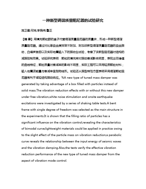
Tuned Mass Dampers (2 D.O.F)

(k + k
1
(k
2
2
− m2ω 2 F0
2
− m1ω
)( k
)
2
2 − m2ω 2 − k2
)
X2 =
(k + k
1
k2 F0
2
− m1ω
2
)( k
2
2 − m2ω 2 − k2
)
Lecture 20-Tuned Mass Damper
MEEM 3700
7
Vibration Absorber
X1 =
c1
Lecture 20-Tuned Mass Damper
MEEM 3700
13
Vibration Absorber: Damped System
X1 =
⎡ k1 − m1ω ⎣
(
2
)( k
F0 k2 − m2ω 2 + jc2ω
2
(
− m2ω
2
)−m k ω
2 2
)
2
⎤ + jω c2 k1 − m1ω 2 − m2ω 2 ⎦
(
)
X2 =
(k
X 1 ( k2 + jω c2 )
2
− m2ω 2 + jω c2
)
Lecture 20-Tuned Mass Damper
MEEM 3700
14
7
Vibration Absorber: Damped System
μ=
m2 = Mass ratio = Absorber mass / main mass m1 F0 = Static deflection of the system k1 k2 = Square of the natural frequency of the absorber m2 k1 = Square of the natural frequency of the main mass m1
摩缇马帝multimatic底盘及调教简介

Objective Testing
Multimatic’s unique multi-post rig testing and vehicle characterisation techniques offer an easily interpreted objective-based methodology for assessing a vehicle’s ride and handling performance. Using in-house developed servo-hydraulic actuators in conjunction with a proprietary controller and software suite, a vehicle’s dynamic signature can be identified. The analysis returns data on the dynamic characteristics of the vehicle’s structure, suspension and tires as well as an overall assessment of performance.
Closed-Loop Vehicle Closed-Loop Vehicle Dynamics Optimisation Dynamics Optimization
Multimatic provides development and tuning services that integrate three crucial testing and evaluation disciplines into a “Closed-Loop Vehicle Dynamics Optimisation” process.
一种新型调谐质量阻尼器的试验研究
一种新型调谐质量阻尼器的试验研究施卫星;何斌;李晓玮;鲁正【摘要】用填充颗粒群的盒子代替调谐质量阻尼器的质量块,形成一种新型调谐质量阻尼器。
通过对比单自由度排架不附加、附加该新型调谐质量阻尼器的自由振动,白噪声激励以及实际地震输入下的振动台试验,考察了该新型阻尼器对结构的减振控制效果。
试验研究表明:颗粒的填充率对振动衰减影响明显,表现出双峰值的曲线特征;颗粒质量对衰减率的影响不明显,实际工程可以采用轻质颗粒材料;输入地震波能量与衰减率呈抛物线形。
试验还从振型特性方面表明采用调谐颗粒阻尼器有利于减轻结构振动响应。
%A new type of tuned mass damper was generated by taking advantage of a box filled with particles instead of solid mass.The vibration reduction effects with or without this new damper under free vibration,white noise stimulation and onsite earthquake excitations were investigated by a series of shaking table tests.A bent frame with single degree of freedom was selected as the main structure in the experiments.It is shown that the filling ratio of particles has a significant influence on the vibration control,revealing the characteristics of bimodal curve;lightweight materials could be applied in practice owing to the slight effect of the particle mass on vibration reduction;a parabolic curve reveals the relationship between the input energy of seismic waves and the vibration damping.Also,the tests verify the effective vibration reduction performance of the new type of tuned mass damper from the aspect of vibration mode control.【期刊名称】《振动与冲击》【年(卷),期】2015(000)012【总页数】5页(P207-211)【关键词】新型调谐质量阻尼器;振动台试验;结构振动控制;影响因素【作者】施卫星;何斌;李晓玮;鲁正【作者单位】同济大学结构工程与防灾研究所,上海 200092;同济大学结构工程与防灾研究所,上海 200092;同济大学建筑设计研究集团有限公司,上海200092;同济大学结构工程与防灾研究所,上海 200092【正文语种】中文【中图分类】TU352;TB535单摆式调谐质量阻尼器(TMD)主要由摆绳、质量块和阻尼器组成。
高位卧式容器基础设计要点

变/应力关系、静态刚度等性能指标。
参考文献[1]和昆原.液压式摩擦阻尼器的研究[J].煤矿机械,2012(8):60-62.[2]颜学渊,王璇,曹晨,等.复合型阻尼器研究进展[J].地震工程与工程振动,2020,40(3):54-70.[3]Wang Z,Li H N,Song G.Aeolian vibration control of power transmi-ssion line using stockbridge type dampers—A review[J].International journal of structural stability and dynamics,2021,21(1):2130001.[4]郑一峰,钱盛域.黏滞阻尼器与钢阻尼器在桥梁横向震动控制中的应用[J]. 华南理工大学学报(自然科学版),2021,49(12):89-100.[5]Wang L,Shi W,Zhou Y.Adaptive-passive tuned mass damper for structural aseismic protection including soil–structure interaction[J].Soil dynamics and earthquake engineering,2022,158(7):107298.[6]程扬,许卫晓,杨伟松,等.分阶段屈服金属阻尼器研究综述[J].青岛理工大学学报,2022,43(3):83-92.[7]孔金震,钱亚鹏,贺枫,等.大型液压阻尼器仿真建模及静动态性能试验研究[J].噪声与振动控制,2021,41(1):82-88.[8]Wang W L,Yu D S,Huang Y,et al.A locomotive ’s dynamic response to in-service parameter variations of its hydraulic yaw damper[J].Nonlinear dynamics,2014,77(4):1485-1502.[9]范家俊,吴刚,冯德成,等.新型消能减震阻尼器滞回性能试验研究及有限元分析[J].东南大学学报(自然科学版),2019,49(3):413-419.[10]侯和涛,仇锦,刘晓芳,等.带U 形板钢阻尼器拟静力试验与有限元分析[J].工业建筑,2017,47(10):175-179,134.图2 “U”形头组件模型图3 框架模型0.00300.000.001000.00500.001500.002000.00150.00450.00600.00(mm)(mm)YYXXZZ由于原油处理量增加,新工艺的要求也相应增加,因此卧式容器的规模增大,放置高度也不断增加,高位卧式容器基础设计非常常见。
磁流变减振器的外特性及非线性特性
磁流变减振器的外特性及非线性特性王靖岳;郭胜;王浩天【摘要】In order to study the motion state of the Magnetorheological (MR) damper, the influence of the cur-rent and the piston velocity on the external characteristics of the MR damper is investigated by using the test data of the MTS849 damper test bench .Considering the nonlinear characteristics of magnetorheological damping force , Using LabVIEW software to design the program diagram of the polynomial and the front panel , and the damping force of MR damper polynomial fitting simulation , accurate polynomial mathematical model is established , and in comparison with the use of MATLAB software to establish a polynomial model and the data of test bench test .The results show that when the speed is constant , the damping force increases with the increase of the control current . The damping force increases relatively slowly when the current is small , and the damping force increases rapidly when the current is larger .When the current is constant , the damping force increases with the increase of piston speed .The polynomial model fitted by LabVIEW software is more close to the experimental data curve , which shows that the polynomial mathematical model can well describe the hysteretic and nonlinear characteristics of the damping force of the MR damper .%为了更好地研究控制磁流变减振器的运动状态,运用MTS849减振器试验台测试的试验数据来探究电流和活塞运动速度对磁流变减振器外特性的影响.考虑到磁流变阻尼力非线性的特性,运用LabVIEW软件设计出了多项式的程序框图和前面板,并进行了磁流变减振器阻尼力的多项式拟合仿真,准确地建立了多项式数学模型,并与利用MATLAB软件建立的多项式模型和试验台测试的数据相比较.结果表明:当速度一定时,随着控制电流的增加,减振器阻尼力也随着增加,电流较小时阻尼力增加相对较慢,电流较大时阻尼力增加相对较快;当电流一定时,减振器阻尼力随着活塞速度的增加而增加.运用LabVIEW软件拟合的多项式模型更接近试验数据曲线,说明该多项式数学模型能很好地描述磁流变减振器阻尼力的滞回特性和非线性特性.【期刊名称】《科学技术与工程》【年(卷),期】2017(017)034【总页数】5页(P332-336)【关键词】磁流变阻尼器;LabVIEW;多项式模型;滞回特性;非线性【作者】王靖岳;郭胜;王浩天【作者单位】沈阳理工大学汽车与交通学院,沈阳 110159;沈阳理工大学汽车与交通学院,沈阳 110159;沈阳航空航天大学自动化学院,沈阳110136【正文语种】中文【中图分类】U461.4磁流变液(MRF)是一种低磁滞性、高磁导率的微小软磁性颗粒,与非导磁性液体混合组成的智能材料[1]。
振动控制优化质量布置
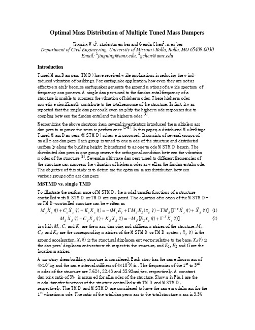
Optimal Mass Distribution of Multiple Tuned Mass DampersJingning Wu 1, student member and Genda Chen 2, memberDepartment of Civil Engineering, University of Missouri-Rolla, Rolla, MO 65409-0030Email: 1jingning@, 2gchen@IntroductionTuned Mass Dampers (TMD) have received wide applications in reducing the wind-induced vibration of buildings. For earthquake application, however, they are not as effective mainly because earthquakes generate the ground motions of a wide spectrum of frequency components. A single damper tuned to the fundamental frequency of a structure is unable to suppress the vibration of higher modes. These higher modes sometime significantly contribute to the total response of the structure. In fact, it was reported that the single damper could even amplify the higher mode responses due to coupling between the fundamental and the higher modes [1].Recognizing the above shortcomings, several investigators introduced the multiple mass dampers to improve the seismic performance [2-5]. In this paper, a distributed Multi-Stage Tuned Mass Dampers (MSTMD) scheme is proposed. It consists of several groups of small mass dampers. Each group is tuned to one mode of the structure and distributed uniformly along the building height. It is referred to as one-mode MSTMD herein. The distributed dampers in one group reserve the orthogonal condition between the vibration modes of the structure [6]. Several multi-stage dampers tuned to different frequencies of the structure can suppress the vibration of higher modes as well as the fundamental mode. The objective of this study is to determine the optimum mass distribution between various groups of mass dampers.MSTMD vs. single TMDTo illustrate the performance of MSTMD, the modal transfer functions of a structurecontrolled with MSTMD or TMD are compared. The equation of motion of the MSTMD- or TMD-controlled structure can be written as)]()([)()()()()(t X t X M t x E M E M t X K t X C t X M d s T d g 2d 1s s s s s s s &&&&&&&&&+−+−=++ΓΓΓ (1))]()([)()()(t X t x E M t X K t X C t X M s T g 2d d d d d d d &&&&&&&Γ+−=++ (2) in which M s , C s and K s are the mass, damping and stiffness matrices of the structure; M d ,C d and K d are the corresponding matrices of the MSTMD or TMD system; )(t xg && is the ground acceleration, X s (t ) is the structural displacement vector relative to the base, X d (t ) is the dampers’ displacement vector with respect to the structure, and E 1, E 2 and G are the location matrices.A six-story shear building structure is considered. Each story has the same floor mass of 4×10⁴kg and the same interval stiffness of 4×10⁷N/m. The frequencies of the 1st to 3rd modes of the structure are 7.624, 22.43 and 35.93rad/sec, respectively. A constant damping ratio of 3% is assumed for all modes of the structure. Shown in Fig.1 are the modal transfer functions of the structure controlled with TMD and MSTMD,respectively. The TMD and MSTMD are considered to have the same modal mass for the 1st vibration mode. The ratio of the total damper mass to the total structure mass is 3.3%for TMD and 6% for MSTMD. Two cases are considered for MSTMD. All the dampers are either tuned to the 1st mode only (MSTMD1) or tuned to both the 1st and the 2nd modes (MSTMD2). For the second case, the mass ratio between the oscillators tuned to the 1st and those to the 2nd modes is 3 to 2. The frequency and damping parameters of the MSTMD system are determined using the equations for a single TMD scheme [7,8].10-410-310-210-1100010203040Frequency (rad/sec)D i s p l a c e m e n tFig. 1 Modal transfer functions of the controlled structure It can be clearly seen that only when the dampers are tuned to higher modes, can the responses of the higher modes be reduced. The transfer functions of the structure controlled with MSTMD1 are almost the same as those with TMD except for the significant amplification of the higher-mode responses at the fundamental frequency in the latter case. The appreciable increase in response results from the coupling between the vibration modes of the structure due to the presence of a single mass damper. However, compared with the response magnitude of the 1st mode, the effect of the increase in higher mode response on the overall response is negligible for regularstructures. Therefore, the MSTMD1 control scheme is not as efficient as a single TMD in suppressing the peak response since it requires a significantly larger mass for a group of dampers (6% vs. 3.3%).Fig.1 also indicates that the single TMD is as effective as the MSTMD2 control scheme for low frequency disturbances such as wind loads. When the structure is subjected to high frequency excitations, however, the multiple tuning in the MSTMD2 scheme appeals considerably more effective. Optimal mass distribution among dampers tuned to different modesClosed-form solutionFor an N -story shear building structure without TMD or MSTMD, the absolute acceleration in frequency domain can be written as∑==N1i g i i i i x H X )()/()(ωγΦωωω&&&& (3)where H i , Φi , and γi are the transfer function, modal vector and participation factor of the i th mode, respectively. The transfer function can be further expressed intoj21j21H i i 2i i i i i βξββξβ+−+=)( (4)in which i i ωωβ/=, ωi and ξi are the frequency and damping ratio of the i th mode, and 1j −= is an imaginary unit of a complex number. The mean square acceleration at the k th floor can then be expressed into∑∫∑=∞==N 1i 0g i i l l i l ik N1l lk 2kd S H H X E ωωωωωωγγΦΦ)()/()/(][*&& (5) in which S g (ω) is the power spectrum of seismic input. In this study, the widely-used Kanai-Tajimi spectrum is employed2g 2g 22g 22g 2g 0g 4141S S )/()/()/()(ωωξωωωωξω+−+= (6) in which ωg and ξg are the spectral parameters and S 0 is related to the earthquake intensity. For this study, ξg is taken as 0.32.For the proposed MSTMD scheme, the multi-stage dampers tuned to one mode of the structure do not strongly interact with other modes. Therefore, the entire structure-MSTMD system can be approximated into a combination of many two-degree-of-freedom subsystems. Each subsystem consists of a single-degree-of-freedom (SDOF) representation to the structure and a lumped damper, representing the effect of one multi-stage dampers. To further simplify the derivation, every subsystem is approximated into an equivalent SDOF oscillator of frequency ωi and equivalent damping ratio ξei . Then the total responses of the structure can be obtained by the conventional modal superposition method from Eqs. (3) to (6) with ξi replaced by ξei . For each mode, the equivalent damping ratio can be approximately determined by [7]i i ei ξρξ8.04/+= (7)which is originally suggested for SDOF-TMD systems. Here, ρi is the damper-to-structure modal mass ratio of the i th mode. For MSTMD systems it is the ratio of the total mass from the i th multi -stage dampers to the total structural mass.The MSTMD2 control scheme is considered below for the detailed derivation of the optimal mass distribution. When the objective is to minimize the acceleration at the k th floor under a constrained total damper-to-structure mass ratio, the optimal mass distribution can be obtained by solving0X E 12k =∂∂ρ][&&, ρ1+ρ2=ρ (constant) . (8) However, the complete form of Eq.(8) is still very complex to evaluate. By dropping the cross terms due to the well-spaced natural frequencies of a regular building structure, Eq.(5) can be simplified into()()∑∑+==++−++++−+=N 1N i i2i 2g 4i 2i 0i 2i 2g 2i 2ik N 1i ei 2i 2g 4i 2i 0i 2i 2g 2i 2ik 2k 114214S 414214S 41X E ξαξααπωαξγΦξαξααπωαξγΦ)(/)(/][&& ∑∑+==+=N 1N i i ik N 1i ei ik 11C C ξξ// (9)in which g i i ωωα/= and N 1 is the number of modes considered. For the case under investigation, N 1 =2. By substituting Eq.(7) into Eq.(9), the equation of (9) becomes∑∑+==++=N 1N i i ik N 1i ii ik 2k 11C 804C X E ξξρ/).//(][&&. (10)Eq.(8) then leads to the following equation for the optimal mass ratio, ρ1,opt :()()22opt 1opt 1k 121opt 1opt 1k 2804C 804C ξρρρρξρρ././,,,,+−−=+ (11) For the example structure and a total damper-to-structure mass ratio ρ=0.06, the root-mean-square (RMS) accelerations at different floors were calculated according to Eq.(5) and its approximation, Eq.(10). Shown in Fig. 2 are the normalized RMS responses][/][,2un N 2N X E X E &&&&vs. mass ratio 1ρ for different ωg values. Here,][2NX E && and ][,2un N X E && are respectively the RMS absolute acceleration at the top floor of thecontrolled and uncontrolled structure. The minimum values on these curves correspond to the optimum values of ρ1, which is ρ1,opt in Eq.(11).When ωg is small, the damper mass is mainly distributed to the 1st mode. As ωg increases, the damper mass is distributed more to the 2nd mode. Despite the difference between the curves calculated by the two methods, the positions of their valleys are almost the same. It should also be noted that in the neighborhood of the valleys, the accelerations are insensitive to the mass distribution. Table 1 gives the optimal mass ratios, ρ1,opt , obtainedby using the two methods. From these results, it can be concluded that the simplified analytical method provides solutions with satisfactory accuracy while it significantly saves computational efforts.0.60.70.80.9100.010.020.030.040.050.06N o r m a l i z e d a c c e l e r a t i o nρ1 Fig. 2 12un N 2N X E X E ρ−][/][,&&&& curves for different ωg valuesWhen dampers in the MSTMD scheme are tuned to more than two modes of the structure, the optimal mass distribution between modes can be achieved in the similarway. However, in light of the relative magnitude of modal responses as shown in Fig.1 and the modal participation factors, tuning to more than three modes may not be efficient.Table 1 Optimal mass distribution for MSTMD2 schemeωg (rad/sec)15.0 22.4 29.2 35.9 1ρ– exact 1ρ – approx.0.052 0.034 0.035 0.038 Numerical solutionAlternatively, the optimal mass distribution of multi-stage dampers can be determined by searching all the valid mass ratios and choosing the one corresponding to the minimum responses. Compared with the approximate analytical solution based on Eqs.(10) and(11), numerical solutions are more accurate but require significant more computational effort. When the multi-stage dampers are tuned to three vibration modes of a structure, the optimal damper mass ratio between the 1st and the 2nd modes is determined first. Then with this ratio and the total damper-to-structure mass ratio fixed, the optimal mass ratio between all the dampers tuned to the 3rd mode and the structure are searched. This sequential procedure renders the sub-optimal mass distribution among three modes with sufficient accuracy.For the same example structure and ωg = 29.2rad/sec, the numerical method is used to search the optimal mass distribution among various modes. Presented in Fig.3 are the][/][,2un N 2N X E X E &&&& relation with 1ρ for the MSTMD2 system and with 3ρ for three-mode tuned dampers. The total damper-to-structure mass ratio is ρ=0.06.0.650.750.850.9500.010.020.030.040.050.06N o r m a l i z e d a c c e l e r a t i o n31or ρρFig. 3 Control effectiveness for two- and three-mode MSTMDIt can be observed from Fig.3 that, for the given total mass ratio, the optimal two-mode MSTMD (ρ1=0.03) leads to an additional 12% reduction in acceleration over the one-mode tuned dampers (ρ1=0 or 0.06) while the three-mode MSTMD (ρ3=0.01) onlysuppresses another 1% acceleration over the two-mode MSTMD (ρ=0.0). Therefore, the3three-mode MSTMD control scheme is not necessary for ωg= 29.2rad/sec. Based on the extensive numerical simulations, three-mode MSTMD is sufficient for the response control of regular structures even when ωg is greater.Concluding RemarksTo overcome the shortcomings associated with a single damper, a multi-mode MSTMD system has been proposed to simultaneously control the seismic responses of multiple modes of a structure. Such a system is much more robust than the conventional TMD. Itis unlikely that malfunction of one damper will notably degrade the performance of the MSTMD system. Simple equations are derived to determine the optimal mass distribution among several vibration modes and the RMS accelerations of structures under random loading. The results from these equations are in good agreement with those by numerical analyses. In general, two- or three-mode MSTMD scheme is sufficient to control the dynamic responses of a regular structure. Numerical results indicate that the multi-mode and multi-stage tuning can greatly improve the seismic performance of tuned mass dampers in suppressing the structural responses under high frequency disturbances. AcknowledgementsFinancial supports from the UM Research Board and the Intelligent Systems Center at UMR to complete this study are acknowledged.References1. Chowdhury, A. H., and Iwuchukwu, M. D. (1987). “The past and future of seismiceffectiveness of tuned mass dampers”, Proc. 2nd Int. Symposium Struct. Control (Leipholz, H. H. E. ed), Martinus Nijhoff Publishers,105-127.2. Clark, A. J. (1988). “Multiple passive tuned mass dampers for reducing earthquakeinduced building motion”, Proc. 9th World Conf. Earthquake Engrg., Tokyo-Kyoto, Japan, V, 779-784.3. Xu, K., and Igusa, T. (1994). “Vibration control using multiple tuned mass dampers”,J. Sound Vib. 175(4), 491-503.4. Kareem, A. and Kline, S. (1995). “Performance of multiple mass dampers underrandom loading”, J. Struct. Engrg., 121(2), 348-361.5. Chen, G. (1996). “Multi-stage tuned mass damper”, Proc. 11th World Conf.Earthquake Engrg., Acapulco, Mexico, Paper No. 1326.6. Chen, G. and Soong, T.T. (1996). “Exact solutions to a class of structure-equipmentsystems”, J. Engrg. Mech., ASCE, 122(11), 1093-1100.7. Luft, R. W. (1979). “Optimal tuned mass dampers for buildings”, J. Struct. Division,ASCE,105, ST12, 2766-2772.8. Warburton, G. B., and Ayorinde, E. Q. (1980). “Optimum absorber parameters forsimple systems”, Earthquake Engrg. Struct. Dyn., 8, 219-236.。