Control-M简明操作手册
PNOZ m EF Multi Link 操作手册说明书

PNOZ m EF Multi Link}Configurable control systems PNOZmulti 2This document is a translation of the original document.All rights to this documentation are reserved by Pilz GmbH & Co. KG. Copies may be made for internal purposes. Suggestions and comments for improving this documentation will be gratefully received.Pilz®, PIT®, PMI®, PNOZ®, Primo®, PSEN®, PSS®, PVIS®, SafetyBUS p®,SafetyEYE®, SafetyNET p®, the spirit of safety® are registered and protected trademarks of Pilz GmbH & Co. KG in some countries.SD means Secure Digital1.2Using the documentation4 1.3Definition of symbols42.2Unit features6 2.3Front view73.2System requirements8 3.3Safety regulations8 3.3.1Safety assessment8 3.3.2Use of qualified personnel9 3.3.3Warranty and liability9 3.3.4Disposal9 3.3.5For your safety94.2Functions10 4.3System reaction time11 4.4Block diagram115.2Dimensions in mm12 5.3Connect the base unit and expansion modules136.2Connection15 6.3Download modified project to the PNOZmulti system157.2Fault detection179.2Accessories211Introduction1.1Validity of documentationThis documentation is valid for the product PNOZ m EF Multi Link. It is valid until new docu-mentation is published.This operating manual explains the function and operation, describes the installation andprovides guidelines on how to connect the product.1.2Using the documentationThis document is intended for instruction. Only install and commission the product if youhave read and understood this document. The document should be retained for future ref-erence.1.3Definition of symbolsInformation that is particularly important is identified as follows:NOTICEThis describes a situation in which the product or devices could be dam-aged and also provides information on preventive measures that can betaken. It also highlights areas within the text that are of particular import-ance.INFORMATIONThis gives advice on applications and provides information on special fea-tures.2Overview2.1Scope of supply2.2Unit featuresUsing the product PNOZ m EF Multi Link:Link module to safely connect two configurable control systems PNOZmulti 2.The product has the following features:}Connection options:–Two base units PNOZmulti 2}Can be configured in the PNOZmulti Configurator}Point-to-point connection via 4-core shielded and twisted-pair cable}32 virtual inputs and 32 virtual outputs}Status indicators}Max. 4 PNOZ m EF Multi Link can be connected to the base unit}LEDs for–Operating state–Error–Connection status}Plug-in connection terminals:either spring-loaded terminal or screw terminal available as an accessory (see orderreference)2.3Front viewPowerReadyLinkFaultLegend:}X2:–0 V, 24 V:Supply connections–FE: Functional earth}Link:Connection}LEDs:–Power–Ready–Link–Fault3Safety3.1Intended useThe expansion module is used for the point-to-point connection of safe virtual inputs andoutputs between two base units.The expansion module may only be connected to a base unit from the configurable systemPNOZmulti 2 (please refer to the document "PNOZmulti System Expansion" for details ofthe base units that can be connected).The configurable systems PNOZmulti is used for the safety-related interruption of safety cir-cuits and is designed for use on:}Emergency stop equipment}Safety circuits in accordance with VDE 0113 Part 1 and EN 60204-1The following is deemed improper use in particular:}Any component, technical or electrical modification to the product}Use of the product outside the areas described in this manual}Use of the product outside the technical details (see Technical details [ 18]).NOTICEEMC-compliant electrical installationThe product is designed for use in an industrial environment. The productmay cause interference if installed in other environments. If installed in otherenvironments, measures should be taken to comply with the applicablestandards and directives for the respective installation site with regard to in-terference.3.2System requirementsPlease refer to the "Product Modifications PNOZmulti" document in the "Version overview"section for details of which versions of the base unit and PNOZmulti Configurator can beused for this product.3.3Safety regulations3.3.1Safety assessmentBefore using a unit it is necessary to perform a safety assessment in accordance with theMachinery Directive.Functional safety is guaranteed for the product as a single component. However, this doesnot guarantee the functional safety of the overall plant/machine. In order to achieve the re-quired safety level for the overall plant/machine, define the safety requirements for theplant/machine and then define how these must be implemented from a technical and organ-isational standpoint.3.3.2Use of qualified personnelThe products may only be assembled, installed, programmed, commissioned, operated,maintained and decommissioned by competent persons.A competent person is someone who, because of their training, experience and current pro-fessional activity, has the specialist knowledge required to test, assess and operate thework equipment, devices, systems, plant and machinery in accordance with the generalstandards and guidelines for safety technology.It is the company’s responsibility only to employ personnel who:}Are familiar with the basic regulations concerning health and safety / accident preven-tion}Have read and understood the information provided in this description under "Safety"}And have a good knowledge of the generic and specialist standards applicable to the specific application.3.3.3Warranty and liabilityAll claims to warranty and liability will be rendered invalid if}The product was used contrary to the purpose for which it is intended}Damage can be attributed to not having followed the guidelines in the manual}Operating personnel are not suitably qualified}Any type of modification has been made (e.g. exchanging components on the PCB boards, soldering work etc.).3.3.4Disposalin the safety-re-}In safety-related applications, please comply with the mission time TMlated characteristic data.}When decommissioning, please comply with local regulations regarding the disposal of electronic devices (e.g. Electrical and Electronic Equipment Act).3.3.5For your safetyThe unit meets all the necessary conditions for safe operation. However, you should alwaysensure that the following safety requirements are met:}This operating manual only describes the basic functions of the unit. The expanded functions are described in the PNOZmulti Configurator's online help. Only use thesefunctions once you have read and understood the documentations.}Do not open the housing or make any unauthorised modifications.}Please make sure you shut down the supply voltage when performing maintenance work (e.g. exchanging contactors).Function Description4Function Description4.1Integrated protection mechanismsThe relay conforms to the following safety criteria:}The circuit is redundant with built-in self-monitoring.}The safety function remains effective in the case of a component failure.4.2FunctionsThe link module PNOZ m EF Multi Link is used to safely transfer the input information from32 virtual inputs and 32 virtual outputs between two PNOZmulti systems. One link moduleis assigned to each base unit. Data is exchanged cyclically.The function of the inputs and outputs on the control system depends on the safety circuitcreated using the PNOZmulti Configurator. A chip card is used to download the safety cir-cuit to the base unit. The base unit has 2 microcontrollers that monitor each other. Theyevaluate the input circuits on the base unit and expansion modules and switch the outputson the base unit and expansion modules accordingly.The LEDs on the base unit and expansion modules indicate the status of the configurablecontrol system PNOZmulti.The online help on the PNOZmulti Configurator contains descriptions of the operatingmodes and all the functions of the control system, plus connection examples.Data exchange:}Data is exchanged cyclically.}After the end of a PNOZmulti cycle, each base unit sends its output data to its link mod-ule. This output data is immediately sent to the link module on the other base unit.}At the same time, the base unit reads the input data from the link module.Connection of multiple base units:Any number of base units can be connected via link modules. Two link modules are re-quired for a connection between two base units. However, only a maximum of 4 link mod-ules may be connected to any one base unit.Virtual inputs and outputs:Inputs and outputs for both PNOZmulti systems are assigned in the PNOZmulti Configur-ator. Inputs and outputs with the same number are assigned to each other, e.g. output o5on one PNOZmulti system to input i5 on the other PNOZmulti system.Function DescriptionBase unit 1 Virtual outputs o0...o31Virtual inputs i0...i31Base unit 2 Virtual inputs i0...i31Virtual outputs o0...o314.3System reaction timeCalculation of the maximum reaction time between an input switching off and a linked out-put in the system switching off is described in the document "System Expansion".4.4Block diagram5Installation5.1General installation guidelines}The unit should be installed in a control cabinet with a protection type of at least IP54.}Fit the safety system to a horizontal mounting rail. The venting slots must face upward and downward. Other mounting positions could damage the safety system.}Use the locking elements on the rear of the unit to attach it to a mounting rail.}In environments exposed to heavy vibration, the unit should be secured using a fixing element (e.g. retaining bracket or end angle).}Open the locking slide before lifting the unit from the mounting rail.}To comply with EMC requirements, the mounting rail must have a low impedance con-nection to the control cabinet housing.}The ambient temperature of the PNOZmulti units in the control cabinet must not exceed the figure stated in the technical details, otherwise air conditioning will be required.NOTICEDamage due to electrostatic discharge!Electrostatic discharge can damage components. Ensure against dischargebefore touching the product, e.g. by touching an earthed, conductive sur-face or by wearing an earthed armband.5.2Dimensions in mm5.3Connect the base unit and expansion modulesConnect the base unit and the expansion module as described in the operating instructionsfor the base units.}Connect the black/yellow terminator to the expansion module.}Install the expansion module in the position in which it is configured in the PNOZmulti Configurator.The position of the expansion modules is defined in the PNOZmulti Configurator. The ex-pansion modules are connected to the left or right of the base unit, depending on the type.Please refer to the document "PNOZmulti System Expansion" for details of the number ofmodules that can be connected to the base unit and the module types.6Commissioning6.1WiringThe wiring is defined in the circuit diagram of the PNOZmulti Configurator.Please note:}Information given in the Technical details [ 18] must be followed.}Use copper wire that can withstand 75° C.}The power supply must meet the regulations for extra low voltages with protective sep-aration.} 2 connection terminals are available for each of the supply connections 24 V and 0 V.This means that the supply voltage can be looped through several connections. Thecurrent at each terminal may not exceed 3 A.}The max. cable length between two link modules on a connection with one link module –PNOZ ml1p <V2.0: 100 m–PNOZ ml1p from V2.0, PNOZ mml1p, PNOZ m EF Multi Link: 1000 m}Connect the inputs and outputs from two link modules with 4-core shielded cable. The cables must be twisted in pairs (see "Preparing for operation").}Note the crossover cabling, e.g. CA+ with CB+.}The cables must be classified into a minimum of Category 5 in accordance with ISO/ IEC 11801.6.2Connection6.3Download modified project to the PNOZmulti systemAs soon as an additional expansion module has been connected to the system, the project must be amended using the PNOZmulti Configurator. Proceed as described in the operat-ing instructions for the base unit.NOTICEFor the commissioning and after every program change, you must check whether the safety devices are functioning correctly.7OperationWhen the supply voltage is switched on, the PNOZmulti safety system copies the configur-ation from the chip card.The LEDs "POWER","DIAG", "FAULT", "IFAULT" and "OFAULT" light up on the base unit.The PNOZmulti safety system is ready for operation when the "POWER" and "RUN" LEDson the base unit and the "READY" LED on the PNOZ m EF Multi Link are lit continuously.7.1MessagesLegend:7.2Fault detectionEach base unit contains information about}its own link module (in order, defective, no supply voltage)}the status of the connection (yes, no)}the operating status of the connected base unit (RUN, STOP)When the connection is interrupted, the base units switch the virtual inputs to zero. Thebase units remains in a RUN condition.Defective link module:}The corresponding base unit switches to a STOP condition. The virtual outputs on the link module are set to zero.}The connected base unit remains in a RUN condition.8Technical detailsApprovals BG, CCC, CE, EAC (Eurasian), TÜV, cULus Listedfor Module supplyVoltage24 VKind DCVoltage tolerance-15 %/+20 %Output of external power supply (DC)2,5 WPotential isolation yesAmbient temperatureIn accordance with the standard EN 60068-2-14Temperature range0 - 60 °CStorage temperatureIn accordance with the standard EN 60068-2-1/-2Temperature range-25 - 70 °CClimatic suitabilityIn accordance with the standard EN 60068-2-30, EN 60068-2-78Condensation during operation Not permittedEMC EN 61131-2VibrationIn accordance with the standard EN 60068-2-6Frequency 5 - 55 HzAcceleration1gShock stressIn accordance with the standard EN 60068-2-27Acceleration15gDuration11 msMax. operating height above sea level2000 mAirgap creepageIn accordance with the standard EN 61131-2Overvoltage category IIPollution degree2Rated insulation voltage30 VIn accordance with the standard EN 60529Mounting area (e.g. control cabinet)IP54Housing IP20Type of potential isolation Functional insulationRated surge voltage2500 VPotential isolation between Module and system voltageType of potential isolation Functional insulationDIN railTop hat rail35 x 7,5 EN 50022Recess width27 mmMaterialBottom PCFront PCTop PCConnection type Spring-loaded terminal, screw terminal Mounting type plug-inConductor cross section with screw terminals1 core flexible0,25 - 2,5 mm², 24 - 12 AWG2 core with the same cross section, flexible withoutcrimp connectors or with TWIN crimp connectors0,2 - 1,5 mm², 24 - 16 AWGRigid single-core, flexible multi-core or multi-corewith crimp connector0,5 - 1,5 mm²Torque setting with screw terminals0,5 NmConductor cross section with spring-loaded terminals:Flexible with/without crimp connector0,2 - 2,5 mm², 24 - 12 AWGSpring-loaded terminals: Terminal points per connec-tion2Stripping length with spring-loaded terminals9 mmDimensionsHeight101,4 mmWidth22,5 mmDepth120 mmWeight91 gWhere standards are undated, the 2013-01 latest editions shall apply.8.1Safety characteristic dataNOTICEYou must comply with the safety-related characteristic data in order to achieve the required safety level for your plant/machine.2-channel PL eCat. 4SIL CL 38,82E-09SIL 33,86E-0520All the units used within a safety function must be considered when calculating the safety characteristic data.INFORMATIONA safety function's SIL/PL values are not identical to the SIL/PL values of the units that are used and may be different. We recommend that you use the PAScal software tool to calculate the safety function's SIL/PL values.Order referenceOperating Manual PNOZ m EF Multi Link 1003018-EN-04219Order reference 9.1Product9.2AccessoriesConnection terminalsTerminator, jumperSupportTechnical support is available from Pilz round the clock. Americas Brazil+55 11 97569-2804Canada+1 888-315-PILZ (315-7459)Mexico+52 55 5572 1300USA (toll-free)+1 877-PILZUSA (745-9872)Asia China+86 21 60880878-216 Japan+81 45 471-2281South Korea +82 31 450 0680Australia +61 3 95446300Europe Austria+43 1 7986263-0Belgium, Luxembourg +32 9 3217575France+33 3 88104000Germany+49 711 3409-444Ireland+353 21 4804983Italy+39 0362 1826711Scandinavia +45 74436332Spain+34 938497433Switzerland +41 62 88979-30The Netherlands +31 347 320477Turkey+90 216 5775552United Kingdom +44 1536 462203You can reach our international hotline on: +49 711 3409-444 ****************C M S E ®, I n d u r a N E T p ®, P A S 4000®, P A S c a l ®, P A S c o n fi g ®, P i l z ®, P I T ®, P L ID ®, P M C p r i m o ®, P M C p r o t e g o ®, P M C t e n d o ®, P M D ®, P M I ®, P N O Z ®, P r i m o ®, P SE N ®, P S S ®, P V I S ®, S a f e t y B U S p ®, S a f e t y E Y E ®, S a f e t y N E T p ®, T h E S P I r I T O f S A f E T Y ® a r e r e g i s t e r e d a n d p r o t e c t e d t r a d e m a r k s o f P i l z G m b h & C o . K G i n s o m e c o u n t r i e s . W e w o u l d p o i n t o u t t h a t p r o d u c t f e a t u r e s m a y v a r y f r o m t h e d e t a i l s s t a t e d i n t h i s d o c u m e n t , d e p e n d i n g o n t h e s t a t u s a t t h e t i m e o f p u b l i c a t i o n a n d t h e s c o p e o f t h e e q u i p m e n t . W e a c c e p t n o r e s p o n s i b i l i t y f o r t h e v a l i d i t y , a c c u r a c y a n d e n t i r e t y o f t h e t e x t a n d g r a p h i c s p r e s e n t e d i n t h i s i n f o r m a t i o n . P l e a s e c o n t a c t o u r T e c h n i c a l S u p p o r t i f y o u h a v e a n y q u e s t i o n s .Pilz develops environmentally-friendly products using ecological materials and energy-saving technologies. Offices and production facilities are ecologically designed, environmentally-aware and energy-saving. So Pilz offers sustainability, plus the security of using energy-efficient products and environmentally-friendly solutions.Pilz Gmbh & Co. KG felix-Wankel-Straße 2 73760 Ostfildern, Germany Tel.: +49 711 3409-0 fax: +49 711 3409-133 *************100X X X X -D E -0X 0-0-1-3-000, 2015-00 P r i n t e d i n G e r m a n y © P i l z G m b h & C o . K G , 20151003018-E N -04, 2015-11 P r i n t e d i n G e r m a n y © P i l z G m b H & C o . K G , 2015。
称重控制器说明书

配料秤系配料秤系统统 MW96C简明操作手明操作手册册包括 INCLUDES• 基本设置说明 •操作说明应用于 APPLIESTO•MW96C -配料秤 P-Module•MT8x - 变送器• MW99d4 & MD1 - 重量显示器•变送器软件版本 v5.10 及延续现有参考文件AVAILABLE DOCUMENTATIONCOPYRIGHT © 2011 by EMC Industrial Group Ltd 56 Tarndale Grove, Albany, North Shore, Auckland 0632 PO Box 101 444 North Shore, Auckland 0745, New Zealand 电话 +64-9-415 5110, 传真 +64-9-415 5115 E-mail sales@Web 由于产品改进,实际功能可能与简介书有所差异。
A S WE ARE CONTINUOUSLY IMPROVING OUR PRODUCTS , CHANGES TO THIS SPECIFICATION MAY OCCUR WITHOUT NOTICE .(Document Details: g0 g1 g2 g3 g4 g5 g6 g9 g10 g11 g14 d0 d2 d3 d4 v0 v5 MT8x))产品 说明 参考文件 MW61静态秤系统W EIGHER I NSTRUMENT技术信息简介 简明操作手册 操作说明书 简明设置摘要MW93 变重秤系统W EIGHT C HANGE I NSTRUMENT技术信息简介 简明操作手册 操作说明书 简明设置摘要MW94 冲板流量计系统I MPACT F LOWMETER I NSTRUMENT技术信息简介 简明操作手册 操作说明书 简明设置摘要MW95 皮带秤系统B ELT W EIGHER I NSTRUMENT技术信息简介 简明操作手册 操作说明书 简明设置摘要MW96 配料秤系统W EIGHFEEDER I NSTRUMENT技术信息简介 简明操作手册 操作说明书 简明设置摘要目录C ONTENTS连接电路图 C ONNECTION D IAGRAM4设置指南 SETTING UP GUIDE.....................................5 设置 S ETTINGS ..........................................................5 快捷键 Q UICK K EYS5 初始初始设设置 I NITIAL S ETUP .............................................5 工程计量单位 E NGINEERING U NITS 5 量程范围 M EASURING R ANGE 5 显示数据分辨率 D ISPLAY R ESOLUTION6 标定皮定皮带带速度 & 长度 C ALIBRATE B ELT S PEED & L ENGTH .6 使用手持测速表 W ITH H AND H ELD T ACHOMETER6 标定重量 C ALIBRATE W EIGHT ......................................6 皮带停止 B ELT S TOPPED6 标定修正系定修正系数数 C ALIBRATE C ORRECTION F ACTOR ..............6 实物测试 M ATERIAL T ESTING 6 无修正 N O C ORRECTION7简要设置 – MW96C 变送器 BRIEF SETUP....................8 基本基本设设置 B ASIC S ETTINGS ...........................................8 工程计量单位 E NGINEERING UNITS 8 量程范围 M EASURING RANGE 8 显示数据分辨率 D ISPLAY RESOLUTION8 输入 I NPUTS ..............................................................8 开关量输入 D IGITAL INPUTS8 转速计 & 皮带长度 T ACHO & B ELT LENGTHS 9 称重传感器输入 (称量段重量) L OADCELL INPUT 9 电流/电压输入 (远程流量设定点) C URRENT /V OLTAGE INPUT 9 输入选项 I NPUT OPTIONS9 内部信部信号号 I NTERNAL S IGNALS .....................................10 重量 W EIGHT 10 流量 F LOWRATE 10 总累计量 T OTALISER 10 控制 C ONTROL10 输出 O UTPUTS .........................................................11 模拟量输出 1 (速度命令) A NALOG OUTPUT 1 11 模拟量输出 2 (流量) A NALOG OUTPUT 2 11 开关量输出 D IGITAL OUTPUTS 11 显示器 (MW99 或 MD1) D ISPLAY12 信息信息,,复位 & 最终标终标定定 I NFO , R ESETS & F INAL C AL ......12 变送器控制仪信息 T RANSMITTER I NFORMATION 12 P-Module 卡信息 P-M ODULE I NFORMATION 12 设置复位 R ESET SETTINGS 12 最终标定 F INAL CALIBRATION12简要设置 – 显示器 BRIEF SETUP - DISPLAY..............13 基本基本设设置 B ASIC S ETTINGS .........................................13 时钟 C LOCK13操作 OPERATION.....................................................14 用户操作 U SER O PERATION .......................................14 MD1 显示及操作原理 D ISPLAY AND OPERATING ELEMENTS 14 MD1 显示器15按键 K EYS 15 报警 A LARMS17连接电路图C ONNECTION D IAGRAM设置指南 SETTING UP GUIDE此部分建议了如何进行系统设置,关于变送器及显示器所有设置项的具体细节都可在其后的“设置”部分中找到。
1650简明中文操作手册
Siemens ADVIA 1650 简明中文操作手册西门子医疗诊断设备有限公司一操作流程表……………………………………………………………l-3 二开机……………………………………………………………………1-4 三定标和质控……………………………………………………………1-6 四样本分析………………………………………………………………1-8 五关机……………………………………………………………………1-10 六维护保养………………………………………………………………l-11【下面的流程图指示了常规操作流程】[开机]【定标和质控】[样本分析][关机][维护保养]1.先开电脑主机,显示器、打印机,启动Windows NT操作系统。
2.然后打开水机开关,检查仪器台面是否有障碍物影响针和搅拌棒的移动,避免开机后造成对仪器的损伤。
打开生化仪主机开关,将【Operate/Standby】开关拨至【OPERATE】。
3.当计算机屏幕显示至【Startup】窗口时,选择【New Start】并输入用户密码“Siemens”(bayer)?,然后点击【OK】。
如果选择【Re-start】系统将保留原来的数据。
4.在Operation Panel菜单下,按【INITIALIZE】键执行初始化,使仪器进入【READY】状态。
注:在按【INITIALIZE】键之前请务必确认试剂盘盖已经盖好,以防撞针!5.检查下列组件是否正常或清洁:试剂针及样品针反应盘冲洗站搅拌棒针清洗杯和缓冲液桶稀释盘冲洗站反应杯盖6.点击【Main.】→【System Monitor】,检查系统状态是否正常。
正常状态为:a) Thermo.circ.vol显示流量为2000~6000之间;b) 其余的状态显示均为OK。
7.检查试剂:检查内容包括:系统试剂、化学试剂、清洗液。
a) 打开仪器中间的前门,检查孵育槽油剂、稀释液、Detergent、Conditioner以及离子缓冲液的量是否足够。
MICO变频器操作手册

一、手持操作器介绍:1、操作器的结构手持操作器HPG60(附图一)带6个按钮,一个能显示4行文字的LCD 显示屏。
一个红色LED指示灯和一个9针的RS-232串行接口。
6个按钮分为2组,一组是4个黄色按钮,用于菜单的选择,另一组是2个红色按钮,用来改变参数。
附图一参数设置按钮主菜单变频器当前值(只读)ADJUSTMENT SPEED Vn ×.××m/s ERROR 12 DIRECTIONWRONG二、手持操作器操作说明1、用黄色按钮中的左键和右键可浏览8 个主菜单。
2、用黄色按钮中的上键和下键可浏览8 个主菜单中的子菜单3、改变参数值必须使用红色的按钮。
被修改的参数会不断闪烁直至按下黄色ENTER 键来保存修改或按下黄色QUIT 键恢复原值放弃修改。
4、可通过显示器最下一行来阅读各个按钮的功能参数的改变只能在电机静止时操作5、第一和第二行显示菜单第三行显示不同的数值如电机电流输出电压等若不是处于子菜单中在运行中或在静止中你都可以用黄色按钮来改变数值的显示6、当运行正常时红色LED 灯常亮,但当发生错误时红色LED 灯会不断闪烁。
三、参数说明1、状态监视2、速度菜单3、速度曲线菜单4、起/停车菜单5、驱动菜单6、可选功能菜单7、操作参数菜单8、变频器参数菜单9、电梯总线10、错误信息菜单四、 出厂参数设置列表:主菜单 子菜单数值 ADJUSTMENT SPEED Vn 再平层速度 (转速) 默认 INSPECTION SPEED Vi 检修速度 0.3m/s RUN-IN SPEED V0 爬行速度 0.1m/s INTERIM SPEED V1 低速 厂标 FINAL SPEED V2 中速 厂标 SPEED 速度FINAL SPEED V3 高速厂标 ACCELERATION 加速度 厂标 JERK ACCELERATION 急加速 厂标 DECELERATION 减速度 厂标 JERK DECELERATION 急减速 厂标 BRAKING DISTANCE V1 V1减速距离 OFF BRAKING DISTANCE V2 V2减速距离 OFF SPEED CURVE 速度曲线BRAKING DISTANCE V3 V3减速距离OFF START RETARDATION 启动延时 200ms PREBRAKING SYNCHRON MOTOR 预转矩(同步) 0 BRAKE RAMP 停车斜率 10% DIRECT RUN-IN 直接停靠 OFF START/STOP 启动/停止CATCH-RESCUE 救援OFF P-PART 启动速度 P 默认 I-PART 启动速度 I默认 INTERN CONTROLERSTART SPEED CONT 。
数字程控交换机分机操作简明手册

数字程控交换机分机操作简明手册数字程控交换机是一种先进的通信设备,它在现代通信中起到重要的作用。
作为普通用户,我们需要了解如何正确地使用数字程控交换机的分机功能。
本文将为你提供一份简明的分机操作手册,帮助你更好地利用数字程控交换机的功能。
一、数字程控交换机的基本工作原理数字程控交换机通过数字化技术实现电话通信的连接与转接。
它由信号处理器、控制器、交换矩阵等组成,能够实现电话的呼叫、呼叫转接、通话等功能。
二、数字程控交换机分机操作的基本步骤1. 接听电话当电话响起时,我们需要拿起听筒,按下分机对应的接听键。
如果是分机间通话,我们只需要拨号对方的分机号码即可。
2. 拨打电话想要呼叫其他分机或外线电话时,我们需要按下“外线”键,然后拨号。
拨号时,按下数字键盘上对应的数字即可。
如果是长途呼叫,可能需要在拨号前按下特定的长途拨号码。
3. 通话中的操作在通话中,我们可能需要进行一些操作,如转接电话、保持通话、挂断电话等。
- 转接电话:按下“转接”键后,拨号对方分机或外线电话号码,然后挂断听筒即可实现转接。
- 保持通话:按下“保持”键后,对方将听到背景音乐,我们可以按下“保持”键进行恢复通话。
- 挂断电话:通话结束后,我们需要将听筒放回挂机器上,挂断电话。
如果通话还没结束,我们需要按下“挂断”键。
4. 其他操作除了基本的接听和拨打电话外,数字程控交换机还具有一些额外的功能。
- 通话转移:我们可以设置通话转移功能,将来电转接到其他分机或手机号码。
- 免提通话:按下“免提”键后,我们可以放下听筒,实现免提通话。
- 呼叫等待:当我们正在通话中,另一个来电到达时,我们会听到短暂的提示音,可以选择保持当前通话或接听来电。
三、数字程控交换机故障排除技巧1. 无法接通电话如果拨号后没有响应或者听到忙音,首先检查电话线是否插紧。
如果仍然无法通话,可能是线路故障,请联系网络运营商解决。
2. 无法接听电话如果听筒无声或者杂音较多,可以尝试调整听筒音量,或者检查电话线是否插紧。
Trane VRF系统简易无线遥控器操作手册说明书
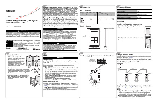
UNITS: inch (mm)
WARNING
Proper Field Wiring and Grounding Required! All field wiring MUST be performed by qualified personnel. Improperly installed and grounded field wiring poses FIRE and ELECTROCUTION hazards.To avoid these hazards, you MUST follow requirements for field wiring installation and grounding as described in NEC and your local/state electrical codes. Failure to follow code could result in death or serious injury.
2.95 (75.0)
0.65 (16.6)
3 Product Specifications
Power supply Power consumption Operating temperature range Operating humidity range Communication Maximum communication length Maximum quantity of controllable devices
2 Pre-installation
Table 1. Components
Remote Cable Cable M4X16 User
U
control tie clamp screw manual Installation terminal
GSK988TA简明安装调试手册2017年4月第2版28定
本手册为最终用户收藏。
V
GSK988TA 车床数控系统 简明安装调试手册
I
GSK988TA 车床数控系统 简明安装调试手册
前言
尊敬的客户:
对您惠顾选用广州数控设备有限公司研发制造的GSK988TA车床数控系统产品,本 公司深感荣幸并深表感谢!
本 手 册 为 GSK988TA 车 床 数 控 系 统 之 简 明 安 装 调 试 手 册 。 本 手 册 简 明 介 绍 了 GSK988TA 车床数控系统安装调试事项。
1.5.1 IOR-04T、IOR-44T 输入插座 ............................................................................................................. 6 1.5.2 IOR-04T、IOR-44T 输出插座 ............................................................................................................. 5 1.5.3 IOR-44T 型号 I/O 单元 ........................................................................................................................ 5 1.5.4 I/O 单元的输入信号 ............................................................................................................................. 7 1.5.5 I/O 单元的输出信号 ............................................................................................................................. 7
SINUMERIK802Dsl简明调试手册.
2.6.1
通电前检查....................................................................................................................... 19
2.6.2
第一次通电....................................................................................................................... 19
2.1.3
机床控制面板(Machine Control Panel)............................................................................. 7
2.1.4
外置编码器接口模块用于连接直接测量系统 ......................................................................... 8
2.6 系统通电............................................................................................................................................ 19
2.1.5
连接 DRIVE-CLiQ 的集线器模块 DMC20 ................................................................................ 8
advia简明中文操作手册
Siemens ADVIA 简明中文操作手册西门子医疗诊断设备有限公司一操作流程表……………………………………………………………l-3 二开机……………………………………………………………………1-4 三定标和质控……………………………………………………………1-6 四样本分析………………………………………………………………1-8 五关机……………………………………………………………………1-10 六维护保养………………………………………………………………l-11[开机]【定标和质控】[样本分析][关机][维护保养]1.先开电脑主机,显示器、打印机,启动Windows NT操作系统。
2.然后打开水机开关,检查仪器台面是否有障碍物影响针和搅拌棒的移动,避免开机后造成对仪器的损伤。
打开生化仪主机开关,将【Operate/Standby】开关拨至【OPERATE】。
3.当计算机屏幕显示至【Startup】窗口时,选择【New Start】并输入用户q 名“advia”和密码“advia”,然后点击【OK】。
如果选择【Re-start】系统将保留原来的数据。
4.在Operation Panel菜单下,按【INITIALIZE】键执行初始化,使仪器进入【READY】状态。
注:在按【INITIALIZE】键之前请务必确认试剂盘盖已经盖好,以防撞针!5.检查下列组件是否正常或清洁:试剂针及样品针反应盘冲洗站搅拌棒针清洗杯和缓冲液桶稀释盘冲洗站反应杯盖6.点击【Main.】→【System Monitor】,检查系统状态是否正常。
正常状态为:a) Thermo.circ.vol显示流量为2000~6000之间;b) 其余的状态显示均为OK。
7.检查试剂:检查内容包括:系统试剂、化学试剂、清洗液。
a) 打开仪器中间的前门,检查孵育槽油剂、稀释液、Detergent、Conditioner以及离子缓冲液的量是否足够。
Pilz PNOZ m EF 16DI 操作手册说明书
PNOZ m EF 16DI}Configurable control systems PNOZmulti 2This document is a translation of the original document.All rights to this documentation are reserved by Pilz GmbH & Co. KG. Copies may be made for internal purposes. Suggestions and comments for improving this documentation will be gratefully received.Pilz®, PIT®, PMI®, PNOZ®, Primo®, PSEN®, PSS®, PVIS®, SafetyBUS p®,SafetyEYE®, SafetyNET p®, the spirit of safety® are registered and protected trademarks of Pilz GmbH & Co. KG in some countries.SD means Secure Digital1.2Using the documentation4 1.3Definition of symbols42.2Unit features6 2.3Front view73.2System requirements8 3.3Safety regulations8 3.3.1Safety assessment8 3.3.2Use of qualified personnel9 3.3.3Warranty and liability9 3.3.4Disposal9 3.3.5For your safety94.2Functions10 4.3System reaction time10 4.4Block diagram105.2Dimensions in mm11 5.3Connecting the base unit and expansion modules116.2Connection13 6.3Download modified project to the PNOZmulti system139.2Accessories181Introduction1.1Validity of documentationThis documentation is valid for the product PNOZ m EF 16DI. It is valid until new docu-mentation is published.This operating manual explains the function and operation, describes the installation andprovides guidelines on how to connect the product.1.2Using the documentationThis document is intended for instruction. Only install and commission the product if youhave read and understood this document. The document should be retained for future ref-erence.1.3Definition of symbolsInformation that is particularly important is identified as follows:NOTICEThis describes a situation in which the product or devices could be dam-aged and also provides information on preventive measures that can betaken. It also highlights areas within the text that are of particular import-ance.INFORMATIONThis gives advice on applications and provides information on special fea-tures.2Overview2.1Scope of supply}Expansion module PNOZ m EF 16DI}Jumper2.2Unit featuresUsing the product PNOZ m EF 16DI:Expansion module for connection to a base unit from the configurable control system .The product has the following features:}Can be configured in the PNOZmulti Configurator}16 inputs for connecting, for example:–E-STOP pushbutton–Two-hand button–Safety gate limit switch–Start button–Light beam devices–Scanner–Enabling switch–PSEN–Operating mode selector switch}LED for:–Error messages–Diagnostics}Test pulse outputs used to monitor shorts across the inputs}Plug-in connection terminals:Either spring-loaded terminal or screw terminal available as an accessory (see orderreference)}Please refer to the document "PNOZmulti System Expansion" for the PNOZmulti base units that can be connected.2.3Front viewLegend:}Inputs I0 – I15}LEDs:–POWER–Run–Diag–Fault–I Fault3Safety3.1Intended useThe expansion module may only be connected to a base unit from the configurable system(please refer to the document "PNOZmulti System Expansion" for details of the base unitsthat can be connected).The configurable system is used for the safety-related interruption of safety circuits and isdesigned for use in:}Emergency stop equipment}Safety circuits in accordance with VDE 0113 Part 1 and EN 60204-1The following is deemed improper use in particular:}Any component, technical or electrical modification to the product}Use of the product outside the areas described in this manual}Use of the product outside the technical details (see Technical details [ 15]).NOTICEEMC-compliant electrical installationThe product is designed for use in an industrial environment. The productmay cause interference if installed in other environments. If installed in otherenvironments, measures should be taken to comply with the applicablestandards and directives for the respective installation site with regard to in-terference.3.2System requirementsPlease refer to the "Product Modifications PNOZmulti" document in the "Version overview"section for details of which versions of the base unit and PNOZmulti Configurator can beused for this product.3.3Safety regulations3.3.1Safety assessmentBefore using a unit it is necessary to perform a safety assessment in accordance with theMachinery Directive.Functional safety is guaranteed for the product as a single component. However, this doesnot guarantee the functional safety of the overall plant/machine. In order to achieve the re-quired safety level for the overall plant/machine, define the safety requirements for theplant/machine and then define how these must be implemented from a technical and organ-isational standpoint.3.3.2Use of qualified personnelThe products may only be assembled, installed, programmed, commissioned, operated,maintained and decommissioned by competent persons.A competent person is someone who, because of their training, experience and current pro-fessional activity, has the specialist knowledge required to test, assess and operate thework equipment, devices, systems, plant and machinery in accordance with the generalstandards and guidelines for safety technology.It is the company’s responsibility only to employ personnel who:}Are familiar with the basic regulations concerning health and safety / accident preven-tion}Have read and understood the information provided in this description under "Safety"}And have a good knowledge of the generic and specialist standards applicable to the specific application.3.3.3Warranty and liabilityAll claims to warranty and liability will be rendered invalid if}The product was used contrary to the purpose for which it is intended}Damage can be attributed to not having followed the guidelines in the manual}Operating personnel are not suitably qualified}Any type of modification has been made (e.g. exchanging components on the PCB boards, soldering work etc.).3.3.4Disposalin the safety-re-}In safety-related applications, please comply with the mission time TMlated characteristic data.}When decommissioning, please comply with local regulations regarding the disposal of electronic devices (e.g. Electrical and Electronic Equipment Act).3.3.5For your safetyThe unit meets all the necessary conditions for safe operation. However, you should alwaysensure that the following safety requirements are met:}This operating manual only describes the basic functions of the unit. The expanded functions are described in the PNOZmulti Configurator's online help. Only use thesefunctions once you have read and understood the documentations.}Do not open the housing or make any unauthorised modifications.}Please make sure you shut down the supply voltage when performing maintenance work (e.g. exchanging contactors).Function description4Function description4.1Integrated protection mechanismsThe relay conforms to the following safety criteria:}The circuit is redundant with built-in self-monitoring.}The safety function remains effective in the case of a component failure.4.2FunctionsThe expansion module provides additional inputs.The function of the inputs on the safety system depends on the safety circuit created usingthe PNOZmulti Configurator. A chip card is used to download the safety circuit to the baseunit. The base unit has 2 microcontrollers that monitor each other. They evaluate the inputcircuits on the base unit and expansion modules and switch the outputs on the base unitand expansion modules accordingly.The online help on the PNOZmulti Configurator contains descriptions of the operatingmodes and all the functions of the PNOZmulti safety system, plus connection examples.4.3System reaction timeCalculation of the maximum reaction time between an input switching off and a linked out-put in the system switching off is described in the document "PNOZmulti System Expan-sion".4.4Block diagram5Installation5.1General installation guidelines}The unit should be installed in a control cabinet with a protection type of at least IP54.}Fit the safety system to a horizontal mounting rail. The venting slots must face upward and downward. Other mounting positions could damage the safety system.}Use the locking elements on the rear of the unit to attach it to a mounting rail.}In environments exposed to heavy vibration, the unit should be secured using a fixing element (e.g. retaining bracket or end angle).}Open the locking slide before lifting the unit from the mounting rail.}To comply with EMC requirements, the mounting rail must have a low impedance con-nection to the control cabinet housing.}The ambient temperature of the PNOZmulti units in the control cabinet must not exceed the figure stated in the technical details, otherwise air conditioning will be required.NOTICEDamage due to electrostatic discharge!Electrostatic discharge can damage components. Ensure against dischargebefore touching the product, e.g. by touching an earthed, conductive sur-face or by wearing an earthed armband.5.2Dimensions in mm5.3Connecting the base unit and expansion modulesConnect the base unit and the expansion modules as described in the operating manualsfor the base modules.}The terminator must be fitted to the last expansion module}Install the expansion module in the position configured in the PNOZmulti Configurator.The position of the expansion modules is defined in the PNOZmulti Configurator. The ex-pansion modules are connected to the left or right of the base unit, depending on the type.Please refer to the document "PNOZmulti System Expansion" for details of the number of modules that can be connected to the base unit and the module types.Commissioning6Commissioning6.1General wiring guidelinesThe wiring is defined in the circuit diagram of the PNOZmulti Configurator.Please note:}Information given in the Technical details [ 15] must be followed.}Use copper wire that can withstand 75° C.6.2Connection6.3Download modified project to the PNOZmulti systemAs soon as an additional expansion module has been connected to the system, the project must be amended using the PNOZmulti Configurator. Proceed as described in the operat-ing instructions for the base unit.NOTICEFor the commissioning and after every program change, you must check whether the safety devices are functioning correctly.Operation7OperationWhen the supply voltage is switched on, the PNOZmulti safety system copies the configur-ation from the chip card.The LEDs “POWER”, “DIAG”, “FAULT”, “IFAULT” and “OFAULT” will light up on the baseunit.The PNOZmulti control system is ready for operation when the "POWER" and "RUN" LEDson the base unit are lit continuously.7.1MessagesLegendLED onLED flashesLED off8Technical detailsApprovals BG, CCC, CE, GOST, TÜV, cULus Listed Application range Failsafefor Module supplyinternal Via base unitVoltage24,0 VKind DCCurrent consumption46 mAPower consumption1,1 WMax. power dissipation of module3,00 WInput voltage in accordance with EN 61131-2 Type 124 V DCInput current at rated voltage 5 mAInput current range2,5 - 5,3 mAPulse suppression0,5 msMaximum input delay8 msAmbient temperatureIn accordance with the standard EN 60068-2-14Temperature range0 - 60 °CForced convection in control cabinet off55 °CStorage temperatureIn accordance with the standard EN 60068-2-1/-2Temperature range-25 - 70 °CClimatic suitabilityIn accordance with the standard EN 60068-2-30, EN 60068-2-78 Condensation during operation Not permittedEMC EN 61131-2VibrationIn accordance with the standard EN 60068-2-6Frequency5,0 - 150,0 HzAcceleration1gShock stressIn accordance with the standard EN 60068-2-27Acceleration15gDuration11 msMax. operating height above sea level2000 mIn accordance with the standard EN 61131-2Overvoltage category IIPollution degree2Rated insulation voltage30 VProtection typeIn accordance with the standard EN 60529Mounting area (e.g. control cabinet)IP54Housing IP20DIN railTop hat rail35 x 7,5 EN 50022Recess width27 mmMax. cable lengthMax. cable length per input1,0 kmMaterialBottom PCFront PCTop PCConnection type Spring-loaded terminal, screw terminal Mounting type plug-inConductor cross section with screw terminals1 core flexible0,25 - 2,50 mm², 24 - 12 AWG2 core with the same cross section, flexible withoutcrimp connectors or with TWIN crimp connectors0,20 - 1,50 mm², 24 - 16 AWGTorque setting with screw terminals0,50 NmConductor cross section with spring-loaded terminals:Flexible with/without crimp connector0,20 - 2,50 mm², 24 - 12 AWGSpring-loaded terminals: Terminal points per connec-tion2Stripping length with spring-loaded terminals9 mmDimensionsHeight101,4 mmWidth22,5 mmDepth120,0 mmWeight95 gWhere standards are undated, the 2012-08 latest editions shall apply.8.1Safety characteristic dataNOTICEYou must comply with the safety-related characteristic data in order to achieve the required safety level for your plant/machine.SC inputs2-channel PL e Cat. 4SIL CL 34,27E-1120SC inputs1-ch., pulsedlight barrier PL eCat. 4SIL CL 32,10E-1020All the units used within a safety function must be considered when calculating the safety characteristic data.INFORMATIONA safety function's SIL/PL values are not identical to the SIL/PL values of the units that are used and may be different. We recommend that you use the PAScal software tool to calculate the safety function's SIL/PL values.Order reference9Order reference 9.1Product9.2AccessoriesConnection terminalsTerminator, jumperSupportTechnical support is available from Pilz round the clock. Americas Brazil+55 11 97569-2804Canada+1 888-315-PILZ (315-7459)Mexico+52 55 5572 1300USA (toll-free)+1 877-PILZUSA (745-9872)Asia China+86 21 60880878-216 Japan+81 45 471-2281South Korea +82 31 450 0680Australia +61 3 95446300Europe Austria+43 1 7986263-0Belgium, Luxembourg +32 9 3217575France+33 3 88104000Germany+49 711 3409-444Ireland+353 21 4804983Italy+39 0362 1826711Scandinavia +45 74436332Spain+34 938497433Switzerland +41 62 88979-30The Netherlands +31 347 320477Turkey+90 216 5775552United Kingdom +44 1536 462203You can reach our international hotline on: +49 711 3409-444 ****************C M S E ®, I n d u r a N E T p ®, P A S 4000®, P A S c a l ®, P A S c o n fi g ®, P i l z ®, P I T ®, P L ID ®, P M C p r i m o ®, P M C p r o t e g o ®, P M C t e n d o ®, P M D ®, P M I ®, P N O Z ®, P r i m o ®, P SE N ®, P S S ®, P V I S ®, S a f e t y B U S p ®, S a f e t y E Y E ®, S a f e t y N E T p ®, T h E S P I r I T O f S A f E T Y ® a r e r e g i s t e r e d a n d p r o t e c t e d t r a d e m a r k s o f P i l z G m b h & C o . K G i n s o m e c o u n t r i e s . W e w o u l d p o i n t o u t t h a t p r o d u c t f e a t u r e s m a y v a r y f r o m t h e d e t a i l s s t a t e d i n t h i s d o c u m e n t , d e p e n d i n g o n t h e s t a t u s a t t h e t i m e o f p u b l i c a t i o n a n d t h e s c o p e o f t h e e q u i p m e n t . W e a c c e p t n o r e s p o n s i b i l i t y f o r t h e v a l i d i t y , a c c u r a c y a n d e n t i r e t y o f t h e t e x t a n d g r a p h i c s p r e s e n t e d i n t h i s i n f o r m a t i o n . P l e a s e c o n t a c t o u r T e c h n i c a l S u p p o r t i f y o u h a v e a n y q u e s t i o n s .Pilz develops environmentally-friendly products using ecological materials and energy-saving technologies. Offices and production facilities are ecologically designed, environmentally-aware and energy-saving. So Pilz offers sustainability, plus the security of using energy-efficient products and environmentally-friendly solutions.Pilz Gmbh & Co. KG felix-Wankel-Straße 2 73760 Ostfildern, Germany Tel.: +49 711 3409-0 fax: +49 711 3409-133 100X X X X -D E -0X 0-0-1-3-000, 2015-00 P r i n t e d i n G e r m a n y © P i l z G m b h & C o . K G , 20151002703-E N -03, 2014-11 P r i n t e d i n G e r m a n y © P i l z G m b H & C o . K G , 2015。
- 1、下载文档前请自行甄别文档内容的完整性,平台不提供额外的编辑、内容补充、找答案等附加服务。
- 2、"仅部分预览"的文档,不可在线预览部分如存在完整性等问题,可反馈申请退款(可完整预览的文档不适用该条件!)。
- 3、如文档侵犯您的权益,请联系客服反馈,我们会尽快为您处理(人工客服工作时间:9:00-18:30)。
Control-M简明操作手册
本手册仅列出一些重要的操作方法,因时间关系,次要的不在此列出,请参考Control-M用户手册。
1.调度的启停
1.1Control-M/EM启停
用ctem用户登录EM服务器,键入root_menu命令,看到以下菜单:
选择其中的“1 - Activation Menu”,进入子菜单:
即可根据情况启动或停止相应的服务。
同时,这个菜单下还可进行EM各服务运行的检查。
1.2Control-M/Server启停
用ctm用户登录Control-M/Server服务器,键入ctm_menu命令,看到以下菜单:
选择其中的“1 - CONTROL-M Manager”,进入子菜单:
根据情况启动或停止相应的服务。
同时,这个菜单下还可进行Server运行的检查。
1.3Control-M/Agent启停
启动Control-M/Agent:用root用户登录Agent节点,进入Agent安装目录下的ctm/scripts
子目录(如果Server和Agent安装在同一节点上则进入ctm_agent/ctm/scripts目录,下同),并执行start-ag –u ctm。
使用root用户启停Agent的原因是只有root才能调用任何一个用户的任何命令。
停止Control-M/Agent:用root用户登录Agent节点,进入Agent安装目录下的ctm/scripts 子目录,并执行shut-ag –u ctm。
2.参数配置
Control-M/EM的参数已在安装过程中设置完毕。
2.1Control-M/Server参数设置
用ctm用户登录Control-M/Server服务器,键入ctm_menu命令,可见以下菜单:
1)选择主菜单中的“6 –Parameter Customization”可查看或设置包括各通讯端口在内的重要参数:
进一步选择1 - Basic Communication and Operational Parameters可以查看或设置“Agent to Server Port”和“Configuration agent Port”等参数,前者在Agent的连接设置中需要使用,后者在用客户端的CONTROL-M Configuraton Manager设置Gateway时需指定。
返回上一级菜单,选择4 - Default Parameters for Communicating with Agent Platforms,可查看或设置Server-to-Agent Port Number等参数,该参数同样在Agent的连接设置中需使用。
2)选择主菜单中的“7 – Node Group”可进行节点组的设置:
2.2Control-M/Agent参数设置
用ctm用户登录Control-M/Agent节点,键入ctmagcfg命令,可见以下菜单:
该菜单可设置Server与Agent通讯的端口(参考2.1节步骤以获取这些端口信息)、主机名等关键信息;同时,选择“7) Advanced parameters”还可进行高级参数的设置,如Agent 的逻辑名、生成日志文件的周期等:
3.日志查看与作业干预
3.1Server日志与作业干预
在Control-M/Server端提供了ctmpsm工具进行作业管理与执行跟踪,ctmpsm的基本菜单如下:
该菜单主要功能涵盖了作业状态查看、Application/Group树与Scheduling Tables查看,数量资源(如进程数)的定义管理,启动作业等等。
选择左侧的“Active Jobs File”任一子菜单均可进入作业查看子菜单,比如要查看作业的具体调度日志,选择“41) List Scheduling Tables”,而后可见配置在Control-M中的所有作业流(在Control-M中称为Table):
进一步选择要查看的Table名称,可见该Table(作业流)下的所有作业状态,但由于Control-M 本身的显示限制,目前19位作业ID在作业状态列表中显示不完整:
上述列表中显示了各作业的OrderNo(Control-M内部唯一标识活动作业的ID),作业在Control-M中的日期,作业状态(包括Wait Cond、Executing、Post proc等)以及当前结果。
在调度外部(如JCI)获得需要查询调度明细的作业ID,而后可通过上述界面的作业列表下方的命令选项“LJ”查看一个作业的执行日志,如下:
上图左侧为作业的调度日期、时间,以及JobName(对应JCI的Sequence ID),右侧显示作业对应的OrderNo(Control-M的活动作业列表AJF中用于唯一标识每个实例的ID)和具体日志信息。
实例的OrderNo对作业干预有重要作用,一个作业配置可能在AJF中有多个实例(取决于order了几次,OrderNo最大的为最新order的实例),如要对调度作业状态进行修改,可先复制实例对应的OrderNo(通常为最大的那个),而后回车,待返回作业列表后,选择相应功能项,如Hold,Rerun等待,粘贴刚才复制的OrderNo后确认即可。
3.2Agent日志
通常,Control-M的作业日志通过Server端工具ctmpsm均可查看;但同时,Control-M 会在Agent端记录日志,并根据设置定时生成日志文件(通过ctmagcfg设置),如果Control-M/Agent单独装在一台机器上,则日志位于ctm用户$HOME/ctm/proclog目录下;如果Agent和Server装在同一个机器上,则日志位于$HOME/ctm_agent/ctm/proclog目录下,文件名均为ctmag_YYYYMMDD.log。