BAW56-V-GS08中文资料
baw56t参数

baw56t参数baw56t是一种型号的电子芯片。
电子芯片是现代电子技术的关键组成部分,它们被广泛应用于各种电子设备中,如计算机、手机、电视机等。
baw56t芯片属于对电流进行控制的场效应晶体管(FET)芯片,具有高性能和稳定性等优点,可以满足复杂电路的要求。
下面将对baw56t芯片进行详细介绍。
首先,baw56t芯片的主要特性是其可靠性和高性能。
该芯片采用了最新的工艺和材料,具有较低的功耗、高的工作频率和稳定的工作温度范围。
它可以在各种环境条件下正常工作,并具有较长的寿命。
这些特性使得baw56t芯片在各种应用中表现出良好的性能。
其次,baw56t芯片具有多种应用领域。
它可以用于模拟电路中,如放大电路、滤波电路和开关电路等。
它也可以用于数字电路中,如逻辑门、存储器和微处理器等。
此外,baw56t芯片还可以用于通信设备、电源管理、医疗设备和汽车电子等领域。
它的多功能性使得它成为各种不同应用的首选芯片。
再次,baw56t芯片的设计和制造过程非常复杂。
它必须通过计算机辅助设计软件来进行电路设计,并使用先进的制造工艺来进行制造。
在制造过程中,需要进行晶圆切割、光刻、薄膜沉积等工艺步骤。
同时,还需要进行严格的质量控制,以确保每一颗芯片都符合规格要求。
这些都要求制造商具备先进的技术和设备,并具有高水平的工程师和技术人员。
最后,baw56t芯片在市场上有很高的竞争力。
随着电子行业的不断发展和技术的不断进步,人们对电子设备的需求也在不断增加。
因此,对于电子芯片的需求也在不断增加。
baw56t作为一种高性能的电子芯片,它可以满足用户的各种需求,并具有较高的市场竞争力。
虽然市场上有许多不同型号的电子芯片,但baw56t芯片凭借其高性能和可靠性,仍然能够吸引许多用户的关注。
总之,baw56t芯片是一种高性能和可靠性的电子芯片,具有多种应用领域。
它的设计和制造过程非常复杂,并且在市场上有很高的竞争力。
随着电子行业的不断发展和技术的不断进步,baw56t芯片有着广阔的应用前景。
BAW56双面切换二极管数据手册说明书

Features∙ Fast Switching Speed∙ Surface Mount Package Ideally Suited for Automated Insertion ∙ For General Purpose Switching Applications∙ Two Diode Elements Connected in a Common Anode Configuration∙ Totally Lead-Free & Fully RoHS Compliant (Notes 1 & 2) ∙ Halogen and Antimony Free. “Green” Device (Note 3) ∙ Qualified to AEC-Q101 Standards for High ReliabilityMechanical Data∙ Case: SOT23∙ Case Material: Molded Plastic. UL Flammability Classification Rating 94V-0∙ Moisture Sensitivity: Level 1 per J-STD-020∙ Terminals: Matte Tin Finish annealed over Alloy 42 Leadframe (Lead Free Plating). Solderable per MIL-STD-202, Method 208 ∙ Polarity: See Diagram∙Weight: 0.008 grams (Approximate)Ordering Information (Note 4)2. See https:///quality/lead-free/ for more information about Diodes Incorporated’s definitions of Halogen - and Antimony-free, "Green" and Lead-free.3. Halogen- and Antimony-free "Green” products are defined as those which contain <900ppm bromine, <900ppm chlorine (<1500ppm total Br + Cl) and <1000ppm antimony compounds.4. For packaging details, go to our website at /products/packages.html.Marking InformationTop ViewSOT23Top ViewInternal SchematicK = SAT (Shanghai Assembly / Test site) JD = Product Type Marking Code YM = Date Code Marking Y = Year (ex: F = 2018)M = Month (ex: 9 = September) C = CAT (Chengdu Assembly / Test site)JD = Product Type Marking Code= Date Code Marking for Chengdu = Year (ex: F = 2018) M = Month (ex: 9 = September)CJDY MKJD Y MYMY(@T = +25°C, unless otherwise specified.)Thermal CharacteristicsNotes: 5. Part mounted on FR-4 substrate PC board with 1inch squared, 2oz copper pad layout.6. Short duration pulse test used to minimize self-heating effect.400T , AMBIENT TEMPERATURE, (°C)Fig. 1 Power Derating Curve, Total Package A P P O W E R D I S S I P A T I O N (m W )D ,1000.110.010.001I , I N S T A N T A N E O U S F O R W A R D C U R R E N T (A )F V , INSTANTANEOUS FORWARD VOLTAGE (V)Fig. 2 Typical Forward Characteristics, Per Element F0.11101001,00010,000V , INSTANTANEOUS REVERSE VOLTAGE (V)Fig. 3 Typical Reverse Characteristics, Per Element R I , I N S T A N T A N E O U S R E V E R S E C U R R E N T (n A )R 0.00.20.40.60.81.81.61.41.21.02.0010204030C , T O T A L C A P A C I T A N C E (p F )T V , DC REVERSE VOLTAGE (V)Fig. 4 Total Capacitance vs. Reverse Voltage, Per Element RPackage Outline DimensionsPlease see /package-outlines.html for the latest version.Suggested Pad LayoutPlease see /package-outlines.html for the latest version.SOT23。
中兴电源培训资料

中兴通讯电源产品技术经理培训教材本部事业部电源系统部二00二年四月目录第一章中兴电源产品部简介 (1)一、中兴通讯电源产品部发展概括 (1)二、中兴通信电源产品种类 (2)第二章通信电源基础知识 (6)第一讲通信电源发展概况 (6)一、通信电源的现状和发展趋势 (6)二、通信设备对电源系统的一般要求 (9)第二讲组合通信电源系统结构及功能 (10)第三章中兴通信电源产品特色 (15)第一讲中兴整流器技术 (15)一、工作基本原理 (15)二、中兴整流器技术特点 (16)第二讲中兴组合电源系统特点 (18)可靠的三级防雷网络 (19)自下而上全分布式的三级监控网络 (20)完善的蓄电池管理 (22)灵活多样的组网方式 (22)第三讲组网方式 (23)第四章中兴组合通信电源产品系列介绍 (27)第一讲ZXD5000 100A整流模块及其组成的电源系统 (27)一、ZXD5000 100A整流模块介绍 (27)二、ZXDU3000、ZXDU1500通讯电源系统简介 (29)第二讲ZXD2400 50A整流模块及其组成的电源系统 (32)一、ZXD2400 50A整流模块介绍 (33)二、ZXDU600E、ZXDU400通讯电源系统简介 (34)第三讲ZXD1500 30A整流模块及其组成的电源系统 (37)一、ZXD1500 30A整流模块介绍 (37)二、ZXDU300(2米高机柜)ZXDU300(1.6米高机柜) 通讯电源系统简介 (39)第四讲ZXD800E 15A整流模块及其组成的电源系统 (41)一、ZXD800E 15A整流模块介绍 (41)二、ZXDU150、ZXDU75、ZXDU45通讯电源系统简介 (43)第五讲+24V组合通信电源系统 (46)第五章中兴UPS产品介绍 (47)ZXUPS S501 (47)ZXUPS S502 (48)ZXUPS S503 (48)ZXUPS S506 (48)ZXUPS S510 (49)ZXUPS M510 (49)ZXUPS M515 (49)ZXUPS M520 (50)ZXUPS M530 (50)ZXUPS L005 (50)ZXUPS L006 (50)第六章通信电源计算配置方法 (52)第七章通信电源市场概述 (55)第一讲国内主要通信电源厂家及其产品特色 (55)一、华为公司 (55)公司背景 (55)产品系列 (56)产品技术特点 (56)我司对策 (57)二、武汉洲际通信电源集团有限公司 (57)公司背景 (57)产品特点 (57)我司对策 (58)三、中达-斯米克电器电子有限公司 (58)公司背景 (58)产品系列 (58)与我司技术优、劣势对比 (59)我司对策 (59)四、珠江电信设备制造有限公司 (59)公司背景 (59)产品系列 (59)产品技术特点 (60)五、新西兰SWITCHTEC公司 (60)公司简介 (60)产品介绍 (60)我司对策 (61)六、亚澳通信电源有限公司 (61)公司概况 (61)产品技术特点简介 (62)我司对策 (62)七、动力源责任有限公司 (63)公司背景 (63)产品介绍 (63)产品优、劣势分析 (64)我司对策 (64)八、通力环电气有限公司 (65)公司背景 (65)产品系列 (65)产品特点 (66)九、意达公司 (67)产品系列 (67)产品技术特点 (68)第二讲我司电源产品市场拓展策略 (68)一、市场分类 (68)二、不同市场拓展策略 (69)三、2002年我司电源产品市场拓展策略 (70)第八章推荐参考书籍清单 (75)第一章中兴电源产品部简介导读:这一章主要介绍了中兴电源产品部的发展概况和现有的产品系列,是本教材的入门篇,各产品系列是本章掌握重点,同时关于产品部的发展、近几年的销售业绩等情况也经常用于客户交流中。
BAW56DW-7-F;BAW56DW-7;中文规格书,Datasheet资料

SURFACE MOUNT SWITCHING DIODE ARRAYFeatures• Fast Switching Speed• Ultra-Small Surface Mount Package• For General Purpose Switching Applications • High Conductance• Two “BAW56” Circuits In One Package • Lead Free/RoHS Compliant (Note 3)• Qualified to AEC-Q101 Standards for High Reliability •"Green" Device (Notes 4 and 5)Mechanical Data• Case: SOT-363• Case Material: Molded Plastic. UL Flammability Classification Rating 94V-0• Moisture Sensitivity: Level 1 per J-STD-020D• Terminals: Solderable per MIL-STD-202, Method 208• Lead Free Plating (Matte Tin Finish annealed over Alloy 42 leadframe). Please see Ordering Information: Note 6, Page 2 • Polarity: See Diagram• Marking Information: See Page 2 •Weight: 0.006 grams (approximate)SOT-363A1A 2C 2C 1C 2C 1 Internal SchematicTOP VIEWTOP VIEWMaximum Ratings @T A = 25°C unless otherwise specifiedCharacteristicSymbol Value Unit Non-Repetitive Peak Reverse Voltage V RM 100 V Peak Repetitive Reverse Voltage Working Peak Reverse Voltage DC Blocking VoltageV RRM V RWM V R 75 V RMS Reverse VoltageV R(RMS) 53 V Forward Continuous Current (Note 1)I FM 300 mA Average Rectified Output Current (Note 1)I O 150 mA Non-Repetitive Peak Forward Surge Current @ t = 1.0μs @ t = 1.0s I FSM2.0 1.0AThermal CharacteristicsCharacteristicSymbol Value Unit Power Dissipation (Note 1)P D 200 mW Thermal Resistance Junction to Ambient Air (Note 1)R θJA 625 °C/W Operating and Storage Temperature Range T J , T STG-65 to +150°CElectrical Characteristics @T A = 25°C unless otherwise specifiedCharacteristicSymbol Min Max Unit Test ConditionReverse Breakdown Voltage (Note 2)V (BR)R 75 ⎯ V I R = 2.5μA Forward VoltageV F⎯0.715 0.855 1.0 1.25 V I F = 1.0mA I F = 10mA I F = 50mA I F = 150mA Reverse Current (Note 2) I R ⎯ 2.5 50 30 25 μA μA μA nA V R = 75VV R = 75V, T J = 150°C V R = 25V, T J = 150°C V R = 20VTotal Capacitance C T ⎯ 2.0 pF V R = 0, f = 1.0MHz Reverse Recovery Timet rr⎯4.0nsI F = I R = 10mA,I rr = 0.1 x I R , R L = 100ΩNotes:1. Device mounted on FR-4 PC board with recommended pad layout, which can be found on our website at/datasheets/ap02001.pdf.2. Short duration pulse test used to minimize self-heating effect.3. No purposefully added lead.4. Diodes Inc.'s "Green" policy can be found on our website at /products/lead_free/index.php.5. Product manufactured with Date Code UO (week 40, 2007) and newer are built with Green Molding Compound. Product manufactured prior to Date Code UO are built with Non-Green Molding Compound and may contain Halogens or Sb2O3 Fire Retardants.BAW56DWDocument number: DS30146 Rev. 10 - 21 of 3March 2008© Diodes Incorporated/Please click here to visit our online spice models database.0.110.010.001I , I N S T A N T A N E O U S F O R W A R D C U R R E N T (A )F V , INSTANTANEOUS FORWARD VOLTAGE (V)Fig. 2 Typical Forward Characteristics, Per Element F300BAW56DWDocument number: DS30146 Rev. 10 - 22 of 3March 2008© Diodes Incorporated0501001502002502505075100125150P , P O W E R D I S S I P A T I O N (m W )D T , AMBIENT TEMPERATURE (C)A °Fig. 1 Power Derating Curve, Total Package Note 10.00.20.40.60.81.81.61.41.21.02.0010204030C , T O T A L C A P A C I T A N C E (p F )T V , DC REVERSE VOLTAGE (V)Fig. 4 Total Capacitance vs. Reverse Voltage, Per Element R101001,00010,000020406080100V , INSTANTANEOUS REVERSE VOLTAGE (V)Fig. 3 Typical Reverse Characteristics, Per Element R I , I N S T A N T A N E O U S R E V E R S E C U R R E N T (n A )ROrdering Information (Note 6)Part Number Case Packaging BAW56DW-7-FSOT-363 3000/Tape & ReelNotes: 6. For packaging details, go to our website at /datasheets/ap02007.pdf.Marking InformationKJC YMK J C Y MKJC = Product Type Marking Code YM = Date Code Marking Y = Year ex: N = 2002 M = Month ex: 9 = SeptemberDate Code KeyYear 2000 2001 2002 2003 2004 2005 2006 2007 2008 2009 2010 2011 2012Code L M N P R S T U V W X Y ZMonth Jan Feb Mar AprMay Jun Jul Aug Sep Oct Nov DecCode 1 2 3 4 5 6 7 8 9 O N D/Package Outline DimensionsBAW56DWDocument number: DS30146 Rev. 10 - 23 of 3March 2008© Diodes IncorporatedSuggested Pad LayoutIMPORTANT NOTICEDiodes Incorporated and its subsidiaries reserve the right to make modifications, enhancements, improvements, corrections or other changes without further notice to any product herein. Diodes Incorporated does not assume any liability arising out of the application or use of any product described herein; neither does it convey any license under its patent rights, nor the rights of others. The user of products in such applications shall assume all risks of such use and will agree to hold Diodes Incorporated and all the companies whose products are represented on our website, harmless against all damages.LIFE SUPPORTDiodes Incorporated products are not authorized for use as critical components in life support devices or systems without the expressed written approval of the President of Diodes Incorporated.SOT-363Dim Min Max A 0.10 0.30 B 1.15 1.35 C 2.00 2.20 D 0.65 Nominal F 0.30 0.40 H 1.80 2.20 J ⎯ 0.10 K 0.90 1.00 L 0.25 0.40 M 0.10 0.25α0° 8° All Dimensions in mmXZYCEEG Dimensions Value (in mm)Z 2.5 G 1.3 X 0.42 Y 0.6 C 1.9 E 0.65/分销商库存信息:DIODESBAW56DW-7-F BAW56DW-7。
BAW56DW中文资料
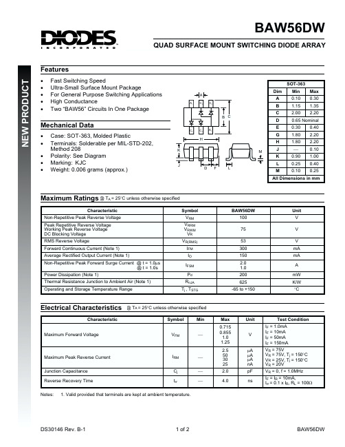
Electrical Characteristics
Characteristic Maximum Forward Voltage
@ TA = 25°C unless otherwise specified Symbol VFM Min ¾ Max 0.715 0.855 1.0 1.25 2.5 50 30 25 2.0 4.0 Unit V mA mA mA nA pF ns Test Condition IF = 1.0mA IF = 10mA IF = 50mA IF = 150mA VR = 75V VR = 75V, Tj = 150°C VR = 25V, Tj = 150°C VR = 20V VR = 0, f = 1.0MHz IF = IR = 10mA, Irr = 0.1 x IR, RL = 100W
· · · · · Case: SOT-363, Molded Plastic Terminals: Solderable per MIL-STD-202, Method 208 Polarity: See Diagram Marking: KJC Weight: 0.006 grams (approx.)
SOT-363
A
A1
Dim
C2
Min 0.10 1.15 2.00 0.30 1.80 1.80 ¾ 0.90 0.25 0.10
Max 0.30 1.35 2.20 0.40 2.20 2.20 0.10 1.00 0.40 0.25
A B
B C
C2
C D E G H
M
Mechanical Data
DS30146 Rev. B-1
1 of 2
BAW56DW
分选仪用户手册-2.0版本

目
录
安全须知...........................................................................................................................................1 公司简介...........................................................................................................................................4 1. 概述.............................................................................................................................................5 1.1 使用对象........................................................................................................................... 5 1.2 测试仪的技术参数........................................................................................................... 5 1.3 工作环境..............................................................................................
卡索金属检测机说明书

金屬檢測機 METAL SHARK® 型號 操作手冊 / 使用說明【中文】
項目:
項目名稱 訂單/項目編號 oc
METAL SHARK®
目錄
目錄 .................................................................................................... 1-2 1. 一般資料......................................................................................... 1-5
2.1. CE–質量符合聲明 ....................................................................... 2-6 2.2. 生產商的聲明 ............................................................................. 2-7 3. 應用及限制範圍................................................................................ 3-8 3.1. 正常使用 ................................................................................... 3-8 3.2. 錯誤使用 ................................................................................... 3-8 3.3. 如何行使擁有人責任的應有注意...................................................... 3-8 3.4. 操作人員的要求 .......................................................................... 3-9 3.5. 服務和維護人員的要求.................................................................. 3-9 4. 一般的安全指示...............................................................................4-10 4.1. 安全符號 ..................................................................................4-10 4.2. 一般的安全指示 .........................................................................4-10 4.3. 金屬檢測機的安全指示.................................................................4-11
BAW56-V中文资料
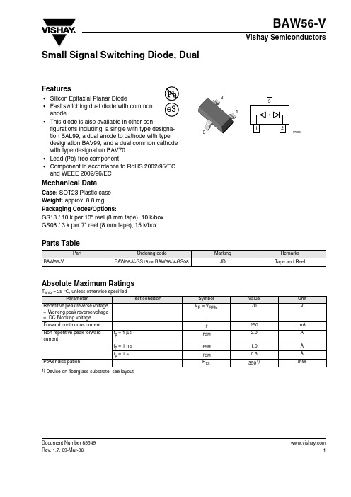
BAW56-VDocument Number 85549Rev. 1.7, 09-Mar-06Vishay Semiconductors1Small Signal Switching Diode, DualFeatures•Silicon Epitaxial Planar Diode•Fast switching dual diode with commonanode•This diode is also available in other con-figurations including: a single with type designa-tion BAL99, a dual anode to cathode with type designation BAV99, and a dual common cathode with type designation BAV70. •Lead (Pb)-free component•Component in accordance to RoHS 2002/95/EC and WEEE 2002/96/ECMechanical DataCase: SOT23 Plastic case Weight: approx. 8.8 mgPackaging Codes/Options:GS18 / 10 k per 13" reel (8 mm tape), 10 k/box GS08 / 3 k per 7" reel (8 mm tape), 15 k/boxParts TableAbsolute Maximum RatingsT amb = 25°C, unless otherwise specified1) Device on fiberglass substrate, see layoutPartOrdering codeMarking Remarks BAW56-VBAW56-V-GS18 or BAW56-V-GS08JDTape and ReelParameterT est condition Symbol Value Unit Repetitive peak reverse voltage = Working peak reverse voltage = DC Blocking voltage V R = V RRM70VForward continuous current I F 250mA Non repetitive peak forward currentt p = 1 μs I FSM 2.0A t p = 1 ms I FSM 1.0A t p = 1 sI FSM 0.5A Power dissipationP tot3501)mW 2Document Number 85549Rev. 1.7, 09-Mar-06BAW56-VVishay Semiconductors Thermal CharacteristicsT amb = 25°C, unless otherwise specified1) Device on fiberglass substrate, see layoutElectrical CharacteristicsT amb = 25°C, unless otherwise specifiedTypical CharacteristicsT amb = 25°C, unless otherwise specifiedParameterTest condition Symbol Value Unit Thermal resistance junction to ambiant airR thJA 430K/W Junction temperature T j 150°C Storage temperature rangeT stg- 65 to + 150°CParameterTest conditionSymbol MinTyp.Max Unit Forward voltageI F = 1 mA V F 715mV I F = 10 mA V F 855mV I F = 50 mA V F 1000mV I F = 150 mAV F 1250mV Reverse currentV R= 70 VI R 2.5µA V R = 70 V , T j = 150°C I R 100µA V R = 25 V , T j = 150°CI R 30µA Diode capacitance V F = V R = 0, f = 1 MHz C tot 2pF Reverse recovery timeI F = 10 mA to I R = 1 mA, V R = 6 V , R L = 100 Ωt rr6nsFigure 1. Forward Current vs. Forward VoltageV F -For w ard V oltage (V )14356Figure 2. Peak forward current I FM = f (t p )BAW56-VDocument Number 85549Rev. 1.7, 09-Mar-06Vishay Semiconductors3Package Dimensions in mm (Inches) 4Document Number 85549 Rev. 1.7, 09-Mar-06BAW56-VVishay SemiconductorsOzone Depleting Substances Policy StatementIt is the policy of Vishay Semiconductor GmbH to1.Meet all present and future national and international statutory requirements.2.Regularly and continuously improve the performance of our products, processes, distribution and operatingsystems with respect to their impact on the health and safety of our employees and the public, as well as their impact on the environment.It is particular concern to control or eliminate releases of those substances into the atmosphere which are known as ozone depleting substances (ODSs).The Montreal Protocol (1987) and its London Amendments (1990) intend to severely restrict the use of ODSs and forbid their use within the next ten years. Various national and international initiatives are pressing for an earlier ban on these substances.Vishay Semiconductor GmbH has been able to use its policy of continuous improvements to eliminate the use of ODSs listed in the following documents.1.Annex A, B and list of transitional substances of the Montreal Protocol and the London Amendmentsrespectively2.Class I and II ozone depleting substances in the Clean Air Act Amendments of 1990 by the EnvironmentalProtection Agency (EPA) in the USA3.Council Decision 88/540/EEC and 91/690/EEC Annex A, B and C (transitional substances) respectively. Vishay Semiconductor GmbH can certify that our semiconductors are not manufactured with ozone depleting substances and do not contain such substances.We reserve the right to make changes to improve technical designand may do so without further notice.Parameters can vary in different applications. All operating parameters must be validated for each customer application by the customer. Should the buyer use Vishay Semiconductors products for any unintended or unauthorized application, the buyer shall indemnify Vishay Semiconductors against all claims, costs, damages, and expenses, arising out of, directly or indirectly, any claim of personal damage, injury or death associated with such unintended or unauthorized use.Vishay Semiconductor GmbH, P.O.B. 3535, D-74025 Heilbronn, GermanyDocument Number: 91000Revision: 18-Jul-081DisclaimerLegal Disclaimer NoticeVishayAll product specifications and data are subject to change without notice.Vishay Intertechnology, Inc., its affiliates, agents, and employees, and all persons acting on its or their behalf (collectively, “Vishay”), disclaim any and all liability for any errors, inaccuracies or incompleteness contained herein or in any other disclosure relating to any product.Vishay disclaims any and all liability arising out of the use or application of any product described herein or of any information provided herein to the maximum extent permitted by law. The product specifications do not expand or otherwise modify Vishay’s terms and conditions of purchase, including but not limited to the warranty expressed therein, which apply to these products.No license, express or implied, by estoppel or otherwise, to any intellectual property rights is granted by this document or by any conduct of Vishay.The products shown herein are not designed for use in medical, life-saving, or life-sustaining applications unless otherwise expressly indicated. Customers using or selling Vishay products not expressly indicated for use in such applications do so entirely at their own risk and agree to fully indemnify Vishay for any damages arising or resulting from such use or sale. Please contact authorized Vishay personnel to obtain written terms and conditions regarding products designed for such applications.Product names and markings noted herein may be trademarks of their respective owners.元器件交易网。
- 1、下载文档前请自行甄别文档内容的完整性,平台不提供额外的编辑、内容补充、找答案等附加服务。
- 2、"仅部分预览"的文档,不可在线预览部分如存在完整性等问题,可反馈申请退款(可完整预览的文档不适用该条件!)。
- 3、如文档侵犯您的权益,请联系客服反馈,我们会尽快为您处理(人工客服工作时间:9:00-18:30)。
BAW56-VDocument Number 85549Rev. 1.7, 09-Mar-06Vishay Semiconductors1Small Signal Switching Diode, DualFeatures•Silicon Epitaxial Planar Diode•Fast switching dual diode with commonanode•This diode is also available in other con-figurations including: a single with type designa-tion BAL99, a dual anode to cathode with type designation BAV99, and a dual common cathode with type designation BAV70. •Lead (Pb)-free component•Component in accordance to RoHS 2002/95/EC and WEEE 2002/96/ECMechanical DataCase: SOT23 Plastic case Weight: approx. 8.8 mgPackaging Codes/Options:GS18 / 10 k per 13" reel (8 mm tape), 10 k/box GS08 / 3 k per 7" reel (8 mm tape), 15 k/boxParts TableAbsolute Maximum RatingsT amb = 25°C, unless otherwise specified1) Device on fiberglass substrate, see layoutPartOrdering codeMarking Remarks BAW56-VBAW56-V-GS18 or BAW56-V-GS08JDTape and ReelParameterT est condition Symbol Value Unit Repetitive peak reverse voltage = Working peak reverse voltage = DC Blocking voltage V R = V RRM70VForward continuous current I F 250mA Non repetitive peak forward currentt p = 1 μs I FSM 2.0A t p = 1 ms I FSM 1.0A t p = 1 sI FSM 0.5A Power dissipationP tot3501)mW 2Document Number 85549Rev. 1.7, 09-Mar-06BAW56-VVishay Semiconductors Thermal CharacteristicsT amb = 25°C, unless otherwise specified1) Device on fiberglass substrate, see layoutElectrical CharacteristicsT amb = 25°C, unless otherwise specifiedTypical CharacteristicsT amb = 25°C, unless otherwise specifiedParameterTest condition Symbol Value Unit Thermal resistance junction to ambiant airR thJA 430K/W Junction temperature T j 150°C Storage temperature rangeT stg- 65 to + 150°CParameterTest conditionSymbol MinTyp.Max Unit Forward voltageI F = 1 mA V F 715mV I F = 10 mA V F 855mV I F = 50 mA V F 1000mV I F = 150 mAV F 1250mV Reverse currentV R= 70 VI R 2.5µA V R = 70 V , T j = 150°C I R 100µA V R = 25 V , T j = 150°CI R 30µA Diode capacitance V F = V R = 0, f = 1 MHz C tot 2pF Reverse recovery timeI F = 10 mA to I R = 1 mA, V R = 6 V , R L = 100 Ωt rr6nsFigure 1. Forward Current vs. Forward VoltageV F -For w ard V oltage (V )14356Figure 2. Peak forward current I FM = f (t p )BAW56-VDocument Number 85549Rev. 1.7, 09-Mar-06Vishay Semiconductors3Package Dimensions in mm (Inches) 4Document Number 85549 Rev. 1.7, 09-Mar-06BAW56-VVishay SemiconductorsOzone Depleting Substances Policy StatementIt is the policy of Vishay Semiconductor GmbH to1.Meet all present and future national and international statutory requirements.2.Regularly and continuously improve the performance of our products, processes, distribution and operatingsystems with respect to their impact on the health and safety of our employees and the public, as well as their impact on the environment.It is particular concern to control or eliminate releases of those substances into the atmosphere which are known as ozone depleting substances (ODSs).The Montreal Protocol (1987) and its London Amendments (1990) intend to severely restrict the use of ODSs and forbid their use within the next ten years. Various national and international initiatives are pressing for an earlier ban on these substances.Vishay Semiconductor GmbH has been able to use its policy of continuous improvements to eliminate the use of ODSs listed in the following documents.1.Annex A, B and list of transitional substances of the Montreal Protocol and the London Amendmentsrespectively2.Class I and II ozone depleting substances in the Clean Air Act Amendments of 1990 by the EnvironmentalProtection Agency (EPA) in the USA3.Council Decision 88/540/EEC and 91/690/EEC Annex A, B and C (transitional substances) respectively. Vishay Semiconductor GmbH can certify that our semiconductors are not manufactured with ozone depleting substances and do not contain such substances.We reserve the right to make changes to improve technical designand may do so without further notice.Parameters can vary in different applications. All operating parameters must be validated for each customer application by the customer. Should the buyer use Vishay Semiconductors products for any unintended or unauthorized application, the buyer shall indemnify Vishay Semiconductors against all claims, costs, damages, and expenses, arising out of, directly or indirectly, any claim of personal damage, injury or death associated with such unintended or unauthorized use.Vishay Semiconductor GmbH, P.O.B. 3535, D-74025 Heilbronn, GermanyDocument Number: 91000Revision: 18-Jul-081DisclaimerLegal Disclaimer NoticeVishayAll product specifications and data are subject to change without notice.Vishay Intertechnology, Inc., its affiliates, agents, and employees, and all persons acting on its or their behalf (collectively, “Vishay”), disclaim any and all liability for any errors, inaccuracies or incompleteness contained herein or in any other disclosure relating to any product.Vishay disclaims any and all liability arising out of the use or application of any product described herein or of any information provided herein to the maximum extent permitted by law. The product specifications do not expand or otherwise modify Vishay’s terms and conditions of purchase, including but not limited to the warranty expressed therein, which apply to these products.No license, express or implied, by estoppel or otherwise, to any intellectual property rights is granted by this document or by any conduct of Vishay.The products shown herein are not designed for use in medical, life-saving, or life-sustaining applications unless otherwise expressly indicated. Customers using or selling Vishay products not expressly indicated for use in such applications do so entirely at their own risk and agree to fully indemnify Vishay for any damages arising or resulting from such use or sale. Please contact authorized Vishay personnel to obtain written terms and conditions regarding products designed for such applications.Product names and markings noted herein may be trademarks of their respective owners.元器件交易网。