fpga英文文献翻译
FPGA的英文文献及翻译

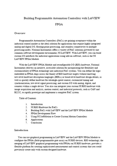
Building Programmable Automation Controllers with LabVIEWFPGAOverviewProgrammable Automation Controllers (PACs) are gaining acceptance within the industrial control market as the ideal solution for applications that require highly integrated analog and digital I/O, floating-point processing, and seamless connectivity to multiple processing nodes. National Instruments offers a variety of PAC solutions powered by one common software development environment, NI LabVIEW. With LabVIEW, you can build custom I/O interfaces for industrial applications using add-on software, such as the NI LabVIEW FPGA Module.With the LabVIEW FPGA Module and reconfigurable I/O (RIO) hardware, National Instruments delivers an intuitive, accessible solution for incorporating the flexibility and customizability of FPGA technology into industrial PAC systems. You can define the logic embedded in FPGA chips across the family of RIO hardware targets without knowinglow-level hardware description languages (HDLs) or board-level hardware design details, as well as quickly define hardware for ultrahigh-speed control, customized timing and synchronization, low-level signal processing, and custom I/O with analog, digital, and counters within a single device. You also can integrate your custom NI RIO hardware with image acquisition and analysis, motion control, and industrial protocols, such as CAN and RS232, to rapidly prototype and implement a complete PAC system.Table of Contents1.Introduction2.NI RIO Hardware for PACs3.Building PACs with LabVIEW and the LabVIEW FPGA Module4.FPGA Development Flowing NI SoftMotion to Create Custom Motion Controllers6.Applications7.ConclusionIntroductionYou can use graphical programming in LabVIEW and the LabVIEW FPGA Module to configure the FPGA (field-programmable gate array) on NI RIO devices. RIO technology, the merging of LabVIEW graphical programming with FPGAs on NI RIO hardware, provides a flexible platform for creating sophisticated measurement and control systems that you could previously create only with custom-designed hardware.An FPGA is a chip that consists of many unconfigured logic gates. Unlike the fixed, vendor-defined functionality of an ASIC (application-specific integrated circuit) chip, you can configure and reconfigure the logic on FPGAs for your specific application. FPGAs are used in applications where either the cost of developing and fabricating an ASIC is prohibitive, or the hardware must be reconfigured after being placed into service. The flexible,software-programmable architecture of FPGAs offer benefits such as high-performance execution of custom algorithms, precise timing and synchronization, rapid decision making, and simultaneous execution of parallel tasks. Today, FPGAs appear in such devices as instruments, consumer electronics, automobiles, aircraft, copy machines, andapplication-specific computer hardware. While FPGAs are often used in industrial control products, FPGA functionality has not previously been made accessible to industrial control engineers. Defining FPGAs has historically required expertise using HDL programming or complex design tools used more by hardware design engineers than by control engineers.With the LabVIEW FPGA Module and NI RIO hardware, you now can use LabVIEW, a high-level graphical development environment designed specifically for measurement and control applications, to create PACs that have the customization, flexibility, andhigh-performance of FPGAs. Because the LabVIEW FPGA Module configures custom circuitry in hardware, your system can process and generate synchronized analog and digital signals rapidly and deterministically. Figure 1 illustrates many of the NI RIO devices that you can configure using the LabVIEW FPGA Module.Figure 1. LabVIEW FPGA VI Block Diagram and RIO Hardware PlatformsNI RIO Hardware for PACsHistorically, programming FPGAs has been limited to engineers who have in-depth knowledge of VHDL or other low-level design tools, which require overcoming a very steep learning curve. With the LabVIEW FPGA Module, NI has opened FPGA technology to a broader set of engineers who can now define FPGA logic using LabVIEW graphical development. Measurement and control engineers can focus primarily on their test and control application, where their expertise lies, rather than the low-level semantics of transferring logic into the cells of the chip. The LabVIEW FPGA Module model works because of the tightintegration between the LabVIEW FPGA Module and the commercial off-the-shelf (COTS) hardware architecture of the FPGA and surrounding I/O components.National Instruments PACs provide modular, off-the-shelf platforms for your industrial control applications. With the implementation of RIO technology on PCI, PXI, and Compact Vision System platforms and the introduction of RIO-based CompactRIO, engineers now have the benefits of a COTS platform with the high-performance, flexibility, and customization benefits of FPGAs at their disposal to build PACs. National Instruments PCI and PXI R Series plug-in devices provide analog and digital data acquisition and control for high-performance, user-configurable timing and synchronization, as well as onboard decision making on a single device. Using these off-the-shelf devices, you can extend your NI PXI or PCI industrial control system to include high-speed discrete and analog control, custom sensor interfaces, and precise timing and control.NI CompactRIO, a platform centered on RIO technology, provides a small, industrially rugged, modular PAC platform that gives you high-performance I/O and unprecedented flexibility in system timing. You can use NI CompactRIO to build an embedded system for applications such as in-vehicle data acquisition, mobile NVH testing, and embedded machine control systems. The rugged NI CompactRIO system is industrially rated and certified, and it is designed for greater than 50 g of shock at a temperature range of -40 to 70 °C.NI Compact Vision System is a rugged machine vision package that withstands the harsh environments common in robotics, automated test, and industrial inspection systems. NICVS-145x devices offer unprecedented I/O capabilities and network connectivity for distributed machine vision applications.NI CVS-145x systems use IEEE 1394 (FireWire) technology, compatible with more than 40 cameras with a wide range of functionality, performance, and price. NI CVS-1455 and NI CVS-1456 devices contain configurable FPGAs so you can implement custom counters, timing, or motor control in your machine vision application.Building PACs with LabVIEW and the LabVIEW FPGA Module With LabVIEW and the LabVIEW FPGA Module, you add significant flexibility and customization to your industrial control hardware. Because many PACs are already programmed using LabVIEW, programming FPGAs with LabVIEW is easy because it uses the same LabVIEW development environment. When you target the FPGA on an NI RIO device, LabVIEW displays only the functions that can be implemented in the FPGA, further easing the use of LabVIEW to program FPGAs. The LabVIEW FPGA Module Functions palette includes typical LabVIEW structures and functions, such as While Loops, For Loops, Case Structures, and Sequence Structures as well as a dedicated set of LabVIEWFPGA-specific functions for math, signal generation and analysis, linear and nonlinear control, comparison logic, array and cluster manipulation, occurrences, analog and digital I/O, and timing. You can use a combination of these functions to define logic and embed intelligence onto your NI RIO device.Figure 2 shows an FPGA application that implements a PID control algorithm on the NI RIO hardware and a host application on a Windows machine or an RT target that communicates with the NI RIO hardware. This application reads from analog input 0 (AI0), performs the PID calculation, and outputs the resulting data on analog output 0 (AO0). While the FPGA clock runs at 40 MHz the loop in this example runs much slower because each component takes longer than one-clock cycle to execute. Analog control loops can run on an FPGA at a rate of about 200 kHz. You can specify the clock rate at compile time. This example shows only one PID loop; however, creating additional functionality on the NI RIO device is merely a matter of adding another While Loop. Unlike traditional PC processors, FPGAs are parallel processors. Adding additional loops to your application does not affect the performance of your PID loop.Figure 2. PID Control Using an Embedded LabVIEW FPGA VI with Corresponding LabVIEW HostVI.FPGA Development FlowAfter you create the LabVIEW FPGA VI, you compile the code to run on the NI RIO hardware. Depending on the complexity of your code and the specifications of your development system, compile time for an FPGA VI can range from minutes to several hours.To maximize development productivity, with the R Series RIO devices you can use abit-accurate emulation mode so you can verify the logic of your design before initiating the compile process. When you target the FPGA Device Emulator, LabVIEW accesses I/O from the device and executes the VI logic on the Windows development computer. In this mode, you can use the same debugging tools available in LabVIEW for Windows, such as execution highlighting, probes, and breakpoints.Once the LabVIEW FPGA code is compiled, you create a LabVIEW host VI to integrate your NI RIO hardware into the rest of your PAC system. Figure 3 illustrates the development process for creating an FPGA application. The host VI uses controls and indicators on the FPGA VI front panel to transfer data between the FPGA on the RIO device and the host processing engine. These front panel objects are represented as data registers within the FPGA. The host computer can be either a PC or PXI controller running Windows or a PC, PXI controller, Compact Vision System, or CompactRIO controller running a real-time operating system (RTOS). In the above example, we exchange the set point, PID gains, loop rate, AI0, and AO0 data with the LabVIEW host VI.Figure 3. LabVIEW FPGA Development FlowThe NI RIO device driver includes a set of functions to develop a communication interface to the FPGA. The first step in building a host VI is to open a reference to the FPGA VI and RIO device. The Open FPGA VI Reference function, as seen in Figure 2, also downloads and runs the compiled FPGA code during execution. After opening the reference, you read and write to the control and indicator registers on the FPGA using the Read/Write Control function. Once you wire the FPGA reference into this function, you can simply select which controls and indicators you want to read and write to. You can enclose the FPGA Read/Write function within a While Loop to continuously read and write to the FPGA. Finally, the last function within the LabVIEW host VI in Figure 2 is the Close FPGA VI Reference function. The Close FPGA VI Reference function stops the FPGA VI and closes the reference to the device. Now you can download other compiled FPGA VIs to the device to change or modify its functionality.The LabVIEW host VI can also be used to perform floating-point calculations, data logging, networking, and any calculations that do not fit within the FPGA fabric. For added determinism and reliability, you can run your host application on an RTOS with the LabVIEW Real-Time Module. LabVIEW Real-Time systems provide deterministicprocessing engines for functions performed synchronously or asynchronously to the FPGA. For example, floating-point arithmetic, including FFTs, PID calculations, and custom control algorithms, are often performed in the LabVIEW Real-Time environment. Relevant data can be stored on a LabVIEW Real-Time system or transferred to a Windows host computer for off-line analysis, data logging, or user interface displays. The architecture for this configuration is shown in Figure 4. Each NI PAC platform that offers RIO hardware can run LabVIEW Real-Time VIs.Figure 4. Complete PAC Architecture Using LabVIEW FPGA, LabVIEW Real-Time and Host PC Within each R Series and CompactRIO device, there is flash memory available to store a compiled LabVIEW FPGA VI and run the application immediately upon power up of the device. In this configuration, as long as the FPGA has power, it runs the FPGA VI, even if the host computer crashes or is powered down. This is ideal for programming safety power down and power up sequences when unexpected events occur.Using NI SoftMotion to Create Custom Motion ControllersThe NI SoftMotion Development Module for LabVIEW provides VIs and functions to help you build custom motion controllers as part of NI PAC hardware platforms that can include NI RIO devices, DAQ devices, and Compact FieldPoint. NI SoftMotion provides all of the functions that typically reside on a motion controller DSP. With it, you can handle path planning, trajectory generation, and position and velocity loop control in the NI LabVIEW environment and then deploy the code on LabVIEW Real-Time or LabVIEW FPGA-based target hardware.NI SoftMotion includes functions for trajectory generator and spline engine and examples with complete source code for supervisory control, position, and velocity control loop using the PID algorithm. Supervisory control and the trajectory generator run on a LabVIEW Real-Time target and run at millisecond loop rates. The spline engine and the control loop can run either on a LabVIEW Real-Time target at millisecond loop rates or on a LabVIEW FPGA target at microsecond loop rates.ApplicationsBecause the LabVIEW FPGA Module can configure low-level hardware design of FPGAs and use the FPGAs within in a modular system, it is ideal for industrial controlapplications requiring custom hardware. These custom applications can include a custom mix of analog, digital, and counter/timer I/O, analog control up to 125 kHz, digital control up to 20 MHz, and interfacing to custom digital protocols for the following:•Batch control•Discrete control•Motion control•In-vehicle data acquisition•Machine condition monitoring•Rapid control prototyping (RCP)•Industrial control and acquisition•Distributed data acquisition and control•Mobile/portable noise, vibration, and harshness (NVH) analysis ConclusionThe LabVIEW FPGA Module brings the flexibility, performance, and customization of FPGAs to PAC platforms. Using NI RIO devices and LabVIEW graphical programming, you can build flexible and custom hardware using the COTS hardware often required in industrial control applications. Because you are using LabVIEW, a programming language already used in many industrial control applications, to define your NI RIO hardware, there is no need to learn VHDL or other low-level hardware design tools to create custom hardware. Using the LabVIEW FPGA Module and NI RIO hardware as part of your NI PAC adds significant flexibility and functionality for applications requiring ultrahigh-speed control, interfaces to custom digital protocols, or a custom I/O mix of analog, digital, and counters.使用LabVIEW FPGA(现场可编程门阵列)模块开发可编程自动化控制器综述工业控制上的应用要求高度集成的模拟和数字输入输出、浮点运算和多重处理节点的无缝连接。
FPGA外文文献
High Level Programming for Real TimeFPGA Based Image ProcessingD Crookes, K Benkrid, A Bouridane, K Alotaibi and A BenkridSchool of Computer Science, The Queen‟s University of Belfast, Belfast BT7 1NN, UK ABSTRACTReconfigurable hardware in the form of Field Programmable Gate Arrays (FPGAs) has been proposed as a way of obtaining high performance for computationally intensive DSP applications such us Image Processing (IP), even under real time requirements. The inherent reprogrammability of FPGAs gives them some of the flexibility of software while keeping the performance advantages of an application specific solution.However, a major disadvantage of FPGAs is their low level programming model. To bridge the gap between these two levels, we present a high level software environment for FPGA-based image processing, which aims to hide hardware details as much as possible from the user. Our approach is to provide a very high level Image Processing Coprocessor (IPC) with a core instruction set based on the operations of Image Algebra. The environment includes a generator which generates optimised architectures for specific user-defined operations.1. INTRODUCTIONImage Processing application developers require high performance systems for computationally intensive Image Processing (IP) applications, often under real time requirements. In addition, developing an IP application tends to be experimental and interactive. This means the developer must be able to modify, tune or replace algorithms rapidly and conveniently.Because of the local nature of many low level IP operations (e.g. neighbourhood operations), one way of obtaining high performance in image processing has been to use parallel computing [1]. However, multiprocessor IP systems have generally speaking not yet fulfilled their promise. This is partly a matter of cost, lack of stability and software support for parallel machines; it is also a matter of communications overheads particularly if sequences of images are being captured and distributed across the processors in real time.A second way of obtaining high performance in IP applications is to use Digital Signal Processing (DSP) processors [2,3]. DSP processors provide a performance improve-ment over standard microprocessors while still maintaining a high level programming model. However, because of the software based control, DSP processors have still difficulty in coping with real time video processing.At the opposite end of the spectrum lie the dedicated hardware solutions. Application Specific Integrated Circuits (ASICs) offer a fully customised solution to a particular algorithm [4]. However, this solution suffers from a lack of flexibility, plus the high manufacturing cost and the relatively lengthy development cycle.Reconfigurable hardware solutions in the form of FPGAs [5] offer high performance, with the ability to be electrically reprogrammed dynamically to perform other algorithms. Though the first FPGAs were only capable of modest integration levels and were thus usedmainly for glue logic and system control, the latest devices [6] have crossed the Million gate barrier hence making it possible to implement an entire System On a Chip. Moreover, the introduction of the latest IC fabrication techniques has increased the maximum speed at which FPGAs can run. Design‟s performance exceeding 150MHz are no longer outside the realm of possibilities in the new FPGA parts, hence allowing FPGAs to address high bandwidth applications such as video processing.A range of commercial FPGA based custom computing systems includes: the Splash-2 system [7]; the G-800 system [8] and VCC‟s HOTWorks HOTI & HOTII development [9]. Though this solution seems to enjoy the advantages of both the dedicated solution and the software based one, many people are still reluctant to move toward this new technology because of the low level programming model offered by FPGAs. Although behavioural synthesis tools have made enormous progress [10, 11], structural design techniques (including careful floorplanning) often still result in circuits that are substantially smaller and faster than those developed using only behavioural synthesis tools [12].In order to bridge the gap between these two levels, this paper presents a high level software environment for an FPGA-based Image Processing machine, which aims to hide the hardware details from the user. The environment generates optimised architectures for specific user-defined operations, in the form of a low level netlist. Our system uses Prolog as the basic notation for describing and composing the basic building blocks. Our current implementation of the IPC is based on the Xilinx 4000 FPGA series [13].The paper first outlines the programming environment at the user level (the programming model). This includes facilities for defining low level Image Processing algorithms based on the operators of Image Algebra [14], without any reference to hardware details. Next, the design of the basic building blocks necessary for implementing the IPC instruction set are presented. Then, we describe the runtime execution environment.2. THE USER’S PROGRAMMING MODELAt its most basic level, the programming model for our image processing machine is a host processor (typically a PC programmed in C++) and an FPGA-based Image Processing Coprocessor (IPC) which carries out complete image operations (such as convolution, erosion etc.) as a single coprocessor instruction. The instruction set of the IPC provides a core of instructions based on the operators of Image Algebra. The instruction set is also extensible in the sense that new compound instructions can be defined by the user, in terms of the primitive operations in the core instruction set. (Adding a new primitive instruction is a task for an architecture designer).The coprocessor core instruction setMany IP neighbourhood operations can be described by a template (a static window with user defined weights) and one of a set of Image Algebra operators. Indeed, simple neighbourhood operations can be split in two stages:∙ A …local‟ operato r applied between an image pixel and the corresponding window coefficient.∙ A …global‟ operator applied to the set of intermediate results of the local operation, to reduce this set to a single result pixel.The set of local operators contains …Add‟ (…+‟) and …multiplication‟ (…*‟), whereas the global operator contains …Accumulation‟ (…∑‟), …Maximum‟ (…Max‟) and …Minimum‟ (…Min‟). With these local and global operators, the following neighbourhood operations can be built:For instance, a simple Laplace operation would be performed by doing convolution (i.e. Local Operation = …∑‟ and Global operation= …*‟) with the following template:The programmer interface to this instruction set is via a C++ class. First, the programmer creates the required instruction object (and its FPGA configuration), and subsequently applies it to an actual image. Creating an instruction object is generally in two phases: firstly build an object describing the operation, and then generate the configuration, in a file. For neighbourhood operations, these are carried out by two C++ object constructors:image_operator (template & operator details)image_instruction (operator object, filename)For instructions with a single template operator, these can be conveniently combined in a single constructor:Neighbourhood_instruction (template, operators, filename)The details required when building a new image operator object include:∙The dimension of the image (e.g. 256 ⨯ 256)∙The pixels size (e.g. 16 bits).∙The size of the window (e.g. 3⨯3).∙The weights of the neighbourhood window.∙The target position within the window, for aligning it with the image pixels (e.g. 1,1).∙The …local‟ and …global‟ operations.Later, to apply an instruction to an actual image, the apply method of the instruction object is used:Result = instruction_object.apply (input image)This will reconfigure the FPGA (if necessary), download the input pixel data and store the result pixels in the RAM of the IPC as they are generated.The following example shows how a programmer would create and perform a 3 by 3 Laplace operation. The image is 256 by 256; the pixel size is 16 bits.2.1 Extending the Model for Compound OperationsIn practical image processing applications, many algorithms comprise more than a single operation. Such compound operations can be broken into a number of primitive core instructions.Instruction Pipelining: A number of basic image operations can be put together in series. A typical example of two neighbourhood operations in series is the …Open‟ operation. To do an …Open‟ operation, an …Erode‟ neighbourhood operation is first performed, and the resulting image is fed into a …Dilate‟ neighbourhood operation as shown in Figure 1.Figure 1 ‘Open’ complex operationThis operation is described as follows in our high level environment:Task parallel: A number of basic image operations can be put together in parallel.For example, the Sobel edge detection algorithm can be performed (approximately) by adding the absolute results of two separate convolutions. Assuming that the FPGA has enough computing resources available, the best solution is to implement the operations in parallel using separate regions of the FPGA chip.Figure 2 Sobel complex operationThe following is an example of the code, based on our high level instruction set, to define and use a Sobel edge detection instruction. The user defines two neighbourhood operators(horizontal and vertical Sobel), and builds the image instruction by summing the absolute results from the two neighbourhood operations.The generation phase will automatically insert the appropriate delays to synchronise the two parallel operations.3. ARCHITECTURES FROM OPERATIONSWhen a new Image_instruction object(e.g. Neighbourhood_instruction) is created (by new), the corresponding FPGA configuration will be generated dynamically. In this section, we will present the structure of the FPGA configurations necessary to implement the high level instruction set for the neighbourhood operations described above. As a key example, the structure of a general 2-D convolver will be presented. Other neighbourhood operations are essentially variations of this, with different local and global operators sub-blocks.A general 2D convolverAs mentioned earlier, any neighbourhood image operation involves passing a 2-D window over an image, and carrying out a calculation at each window position.To allow each pixel to be supplied only once to the FPGA, internal line delays are required. These synchronise the supply of input values to the processing elements, ensuringthat all the pixel values involved in a particular neighbourhood operation are processed at the same instant[15, 16]. Assuming a vertical scan of the image, Figure 3 shows the architecture of a generic 2-D convolver with a P by Q template. Each Processing Element (PE) performs the necessary Multiply/Accumulate operation.Figure 3 Architecture of a generic 2-D, P by Q convolution operation Architecture of a Processing ElementBefore deriving the architecture of a Processing Element, we first have to decide which type of arithmetic to be used- either bit parallel or bit serial processing.While parallel designs process all data bits simultaneously, bit serial ones process input data one bit at a time. The required hardware for a parallel implementation is typically …n‟ times the equivalent serial implementation (for an n-bit word). On the other hand, the bit serial approach requires …n… clock cycles to process an n-bit word while the equivalent parallel one needs only one clock cycle. However, bit serial architectures operates at a higher clock frequency due to their smaller combinatorial delays. Also, the resulting layout in a serial implementation is more regular than a parallel one, because of the reduced number of interconnections needed between PEs (i.e. less routing stress). This regularity feature means that FPGA architectures generated from a high level specification can have more predictable layout and performance. Moreover, a serial architecture is not tied to a particular processing word length. It is relatively straightforward to move from one word length to another withvery little extra hardware (if any). For these reasons, we decided to implement the IPC hardware architectures using serial arithmetic.Note, secondly, that the need to pipeline the bit serial Maximum and Minimum operations common in Image Algebra suggests we should process data Most Significant Bit first (MSBF). Following on from this choice, because of problems in doing addition MSBF in 2‟s complement, there are certain advantages in using an alternative number representation to 2‟s complement. For the p urposes of the work described in this paper, we have chosen to use a redundant number representation in the form of a radix-2 Signed Digit Number system (SDNR) [17]. Because of the inherent carry-free property of SDNR add/subtract operations, the corresponding architectures can be clocked at high speed. There are of course several alternative representations which could have been chosen, each with their own advantages. However, the work presented in this paper is based on the following design choices:∙Bit serial arithmetic∙Most Significant Bit First processing∙Radix-2 Signed Digit Number Representation (SDNR) rather than 2‟s complement.Because image data may have to be occasionally processed on the host processor, the basic storage format for image data i s still, however, 2‟s complement. Therefore, processing elements first convert their incoming image data to SDNR. This also reduces the chip area required for the line buffers (in which data is held in 2‟s complement). A final unit to convert a SDNR resu lt into 2‟s complement will be needed before any results can be returned to the host system. With these considerations, a more detailed design of a general Processing Element (in terms of a local and a global operation) is given in Figure 4.Figure 4 Architecture of a standard Processing ElementDesign of the Basic Building BlocksIn what follows, we will present the physical implementation of the five basic building blocks stated in section 2 (the adder, multiplier, accumulator and maximum/ minimum units). These basic components were carefully designed in order to fit together with as little wastage as possible.The ‘multiplier’ unitThe multiplier unit used is based on a hybrid serial-parallel multiplier outlined in [18]. It multiplies a serial SDNR input with a two‟s complement parallel coefficient B=b N b N-1…b1 as shown in Figure 5. The multiplier has a modular, scaleable design, and comprises four distinct basic building components [19]: Type A, Type B, Type C and Type D. An N bit coefficient multiplier is constructed by:Type A → Type B→ (N-3)*TypeC → Type DThe coefficient word length may be varied by varying the number of type C units. On the Xilinx 4000 FPGA, Type A, B and C units occupy one CLB, and a Type D unit occupies 2 CLBs. Thus an N bit coefficient multiplier is 1 CLB wide and N+1 CLBs high. The online delay of the multiplier is 3.In+In-Figure 5 Design of an N bit hybrid serial-parallel multiplierThe ‘accumulation’ g lobal operation unitThe accumulation unit is the global operation used in the case of a convolution. It adds two SDNR operands serially and outputs the result in SDNR format as shown in Figure 6. The accumulation unit is based on a serial online adder presented in [20]. It occupies 3 CLBs laid out vertically in order to fit with the multiplier unit in a convolver design.Figure 6Block diagram and floorplan of an accumulation unitThe ‘Addition’ local operation unitThis unit is used in additive/maximum and additive/minimum operations. It takes a single SDNR input value and adds it to the corresponding window template coefficient. The coefficient is stored in 2‟s complement format into a RAM addressed by a counter whose period is the pixel word length. To keep the design compact, we have implemented the counter using Linear Feedback Shift Registers (LFSRs). The coefficient bits are preloaded into the appropriate RAM cells according to the counter output sequence. The input SDNR operand is added to the coefficient in bit serial MSBF.+-+-Figure 7. Block diagram and floorplan of an …Addition‟ local operation unitOut-Out+The adder unit occupies 3 CLBs. The whole addition unit occupies 9 CLBs laid out in a 3x3 array. The online delay of this unit is 3 clock cycles.The Maximum/Minimum unitThe Maximum unit selects the maximum of two SDNR inputs presented to its input serially, most significant bit first. Figure 10 shows the transition diagram of the finite state machine performing the maximum …O‟ of two SDNRs …X‟ and ‟Y‟. The physical impl ementation of this machine occupies an area of 13 CLBs laid out in 3 CLBs wide by 5 high. Note that this will allow this unit to fit the addition local operation in an Additive/Maximumneighbourhood operation. The online delay of this unit is 3, compatible with the online delay of the accumulation global operation.*(O=X)*(O=Y)X +X --+Figure 8. State diagram and floorplan of a Maximum unitThe minimum of two SDNRs can be determined in a similar manner knowing that Min(X,Y)=- Max(-X,-Y).5. THE COMPLETE ENVIRONMENTThe complete system is given in Figure 11. For internal working purposes, we have developed our own intermediate high level hardware description notation called HIDE4k [21]. This is Prolog-based [22], and enables highly scaleable and parameterised component descriptions to be written.In the front end, the user programs in a high level software environment (typically C++) or can interact with a Dialog-based graphical interface, specifying the IP operation to be carried out on the FPGA in terms of Local and Global operators, window template coefficients etc. The user can also specify:The desired operating speed of the circuit.∙The input pixel bit-length.∙Whether he or she wants to use our floorplanner to place the circuit or leave this task to the FPGA vendor‟s Placement and Routing tools.The system provides the option of two output circuit description formats: EDIF netlist (the normal), and VHDL at RTL level.Behind the scenes, when the user gives all the parameters needed for the specific IP operation, the intermediate HIDE code is generated. Depending on the choice of the output netlist format, the HIDE code will go through either the EDIF generator tool to generate an EDIF netlist, or the VHDL generator tool to generate a VHDL netlist. In the latter case, the resulting VHDL netlist needs to be synthesised into an EDIF netlist by a VHDL synthesiser tool. Finally, the resulting EDIF netlist will go through the FPGA vendor‟s specific tools to generate the configuration bitstream file. The whole process is invisible to the user, thus making the FPGA completely hidden from the user‟s point of view. Note that the resulting configuration is stored in a library, so it will not be regenerated if exactly the same operation happens to be defined again.Complete and efficient configurations have been produced from our high level instruction set for all the Image Algebra operations and for a variety of complex operations including…Sobel‟, …Open‟ and …Close‟. They have been successfully simulat ed using the Xilinx Foundation Project Manager CAD tools.Figure 10 presents the resulting layout for a Sobel edge detection operation on XC4036EX-2 for 256x256 input image of 8-bits pixels. An EDIF configuration file, with all the placement information, has been generated automatically by our tools from the high level description in 2.1. Note that the generator optimises the design, and uses just a single shared line buffer area for the two (task parallel) neighbourhood operations. The resulting EDIF file is fed to Xilinx PAR tools to generate the FPGA configuration bitstream. The circuit occupies 475 CLBs. Timing simulation shows that the circuit can run at a speed of 75MHz which leads to a theoretical frame rate of 143 frames per second.Figure 10 Physical configuration of Sobel operation on XC4036EX-2 Figure 11 presents the resulting layout for an 'Open' operation on XC4036EX-2 for 256x256 input image of 8-bits pixels. As previously, EDIF configuration file with all the placement information has been generated, automatically by our tools from the correspondinghigh level description presented in section 2.1. The resulting EDIF file is then fed to Xilinx PAR tools to generate the FPGA configuration bitstream. The circuit occupies 962 CLBs. Timing simulation shows that the circuit can run at a speed of 75MHz which leads to a theoretical frame rate of 133 frames per second.Figure 11 Physical configuration of Open operation on XC4036EX-26. CONCLUSIONSIn this paper, we have presented the design of an FPGA-based Image Processing Coprocessor (IPC) along with its high level programming environment. The coprocessor instruction set is based on a core level containing the operations of Image Algebra. Architectures for user-defined compound operations can be added to the system. Possibly the most significant aspect of this work is that it opens the way to image processing application developers toexploit the high performance capability of a direct hardware solution, while programming in an application-oriented model. Figures presented for actual architectures show that real time video processing rates can be achieved when staring from a high level design.The work presented in this paper is based specifically on Radix-2 SDNR, bit serial MSBF processing. In other situations, alternative number representations may be more appropriate. Sets of alternative representations are being added to the environment, including a full bit parallel implementation of the IPC [23]. This will give the user a choice when trying to satisfy competing constraints.Although our basic approach is not tied to a particular FPGA, we have implemented our system on XC4000 FPGA series. However, the special facilities provided by the new Xilinx VIRTEX family (e.g. large on-chip synchronous memory, built in Delay Locked Loops etc.) make it a very suitable target architecture for this type of application. Upgrading our system to operate on this new series of FPGA chips is underway.REFERENCES[1] Webber, H C (ed.), …Image processing and transputers‟, IOS Press, 1992.[2] Rajan, K, Sangunni, K S and Ramakrishna, J, …Dual-DSP systems for signal and image-processing‟, Microprocessing & Microsystems, Vol 17, No 9, pp 556-560, 1993.[3] Akiyama, T, Aono, H, Aoki, K, et al,…MPEG2 video codec using Image compressionDSP‟, IEEE Transactions on Consumer Electronics, Vol 40, No 3, pp 466-472, 1994. [4] L.A. Christopher, W.T. Mayweather and S.S. Perlman, …VLSI median filter for impulsenoi se elimination in composite or component TV signals‟, IEEE Transactions on Consumer Electronics, Vol 34, no. 1, pp. 263-267, 1988.[5] J. Rose and A. Sangiovanni-Vincentelli, …Architecture of Field Programmable GateArrays‟, Proceedings of the IEEE Volume 81, No7, pp 1013-1029, 1993.[6] /products/virtex/ss_vir.htm[6] Arnold, J M, Buell, D A and Davis, E G, …Splash-2‟, Proceedings of the 4th AnnualACM Symposium on Parallel Algorithms and Architectures, ACM Press, pp 316-324, June 1992.[7] Gigaops Ltd., The G-800 System, 2374 Eunice St. Berkeley, CA 94708.[8] Chan, S C, Ngai, H O and Ho, K L, …A programmable image processing system usingFPGAs‟, International Journal of Electronics, Vol 75, No 4, pp 725-730, 1993.[9] /[10] /news/pubs/snug/snug99_papers/Jaffer_Final.pdf[11] FPL99.[12] Hutchings.[13] Xilinx 4000.[14] Ritter G X, Wilson J N and Davidson J L, …Image Algebra: an overview‟, ComputerVision, Graphics and Image Processing, No 49, pp 297-331, 1990.[15] Shoup, R G, …Parameterised Convolution Filtering in an FPGA‟, More FPGAs, WMoore and W Luk (editors), Abington, EE&CS Books, pp 274, 1994.[16] Kamp, W, Kunemund, H, Soldner and Hofer, H, …Programmable 2D linear filter forvideo applications‟, IEEE Journal of Solid State Circuits, pp 735-740, 1990.[17] Avizienis A, …Signed Digit Number Representation for Fast Parallel Arithmetic”, IRETransactions on Electronic Computer, Vol. 10, pp 389-400, 1961.[18] Moran, J, Rios, I and Mene ses, J, …Signed Digit Arithmetic on FPGAs‟, More FPGAs, WMoore and W Luk (editors), Abington, EE&CS Books, pp 250, 1994.[19] Donachy, P, …Design and implementation of a high level image processing machineusing reconfigurable hardware‟, PhD Thesis, Depar tment of Computer Science, The Queen‟s University of Belfast, 1996.[20] Duprat, J, Herreros, Y and Muller, J, …Some results about on-line computation offunction‟, 9th Symposium on Computer Arithmetic, Santa Monica, September 1989. [21]D Crookes, K Alota ibi, A Bouridane, P Donachy and A Benkrid, 1998, …An Environmentfor Generating FPGA Architectures for Image Algebra-based Algorithms‟, ICIP98, Vol.3, pp. 990-994.[22]Clocksin W F and Melish C S, 1994, …Programming in Prolog‟, Springer-Verlag.。
FPGA的文献翻译
Building Programmable Automation Controllers with LabVIEWFPGAOverviewProgrammable Automation Controllers (PACs) are gaining acceptance within the industrial control market as the ideal solution for applications that require highly integrated analog and digital I/O, floating-point processing, and seamless connectivity to multiple processing nodes. National Instruments offers a variety of PAC solutions powered by one common software development environment, NI LabVIEW. With LabVIEW, you can build custom I/O interfaces for industrial applications using add-on software, such as the NI LabVIEW FPGA Module.With the LabVIEW FPGA Module and reconfigurable I/O (RIO) hardware, National Instruments delivers an intuitive, accessible solution for incorporating the flexibility and customizability of FPGA technology into industrial PAC systems. You can define the logic embedded in FPGA chips across the family of RIO hardware targets without knowinglow-level hardware description languages (HDLs) or board-level hardware design details, as well as quickly define hardware for ultrahigh-speed control, customized timing and synchronization, low-level signal processing, and custom I/O with analog, digital, and counters within a single device. You also can integrate your custom NI RIO hardware with image acquisition and analysis, motion control, and industrial protocols, such as CAN and RS232, to rapidly prototype and implement a complete PAC system.Table of Contents1.Introduction2.NI RIO Hardware for PACs3.Building PACs with LabVIEW and the LabVIEW FPGA Module4.FPGA Development Flowing NI SoftMotion to Create Custom Motion Controllers6.Applications7.ConclusionIntroductionYou can use graphical programming in LabVIEW and the LabVIEW FPGA Module to configure the FPGA (field-programmable gate array) on NI RIO devices. RIO technology, the merging of LabVIEW graphical programming with FPGAs on NI RIO hardware, provides a flexible platform for creating sophisticated measurement and control systems that you could previously create only with custom-designed hardware.An FPGA is a chip that consists of many unconfigured logic gates. Unlike the fixed, vendor-defined functionality of an ASIC (application-specific integrated circuit) chip, you can configure and reconfigure the logic on FPGAs for your specific application. FPGAs are used in applications where either the cost of developing and fabricating an ASIC is prohibitive, or the hardware must be reconfigured after being placed into service. The flexible,software-programmable architecture of FPGAs offer benefits such as high-performance execution of custom algorithms, precise timing and synchronization, rapid decision making, and simultaneous execution of parallel tasks. Today, FPGAs appear in such devices as instruments, consumer electronics, automobiles, aircraft, copy machines, andapplication-specific computer hardware. While FPGAs are often used in industrial control products, FPGA functionality has not previously been made accessible to industrial control engineers. Defining FPGAs has historically required expertise using HDL programming or complex design tools used more by hardware design engineers than by control engineers.With the LabVIEW FPGA Module and NI RIO hardware, you now can use LabVIEW, a high-level graphical development environment designed specifically for measurement and control applications, to create PACs that have the customization, flexibility, andhigh-performance of FPGAs. Because the LabVIEW FPGA Module configures custom circuitry in hardware, your system can process and generate synchronized analog and digital signals rapidly and deterministically. Figure 1 illustrates many of the NI RIO devices that you can configure using the LabVIEW FPGA Module.NI RIO Hardware for PACsHistorically, programming FPGAs has been limited to engineers who have in-depth knowledge of VHDL or other low-level design tools, which require overcoming a very steep learning curve. With the LabVIEW FPGA Module, NI has opened FPGA technology to a broader set of engineers who can now define FPGA logic using LabVIEW graphical development. Measurement and control engineers can focus primarily on their test and control application, where their expertise lies, rather than the low-level semantics of transferring logic into the cells of the chip. The LabVIEW FPGA Module model works because of the tight integration between the LabVIEW FPGA Module and the commercial off-the-shelf (COTS) hardware architecture of the FPGA and surrounding I/O components.National Instruments PACs provide modular, off-the-shelf platforms for your industrial control applications. With the implementation of RIO technology on PCI, PXI, and Compact Vision System platforms and the introduction of RIO-based CompactRIO, engineers now have the benefits of a COTS platform with the high-performance, flexibility, and customization benefits of FPGAs at their disposal to build PACs. National Instruments PCI and PXI R Series plug-in devices provide analog and digital data acquisition and control for high-performance, user-configurable timing and synchronization, as well as onboard decision making on a single device. Using these off-the-shelf devices, you can extend your NI PXI or PCI industrial control system to include high-speed discrete and analog control, custom sensor interfaces, and precise timing and control.NI CompactRIO, a platform centered on RIO technology, provides a small, industrially rugged, modular PAC platform that gives you high-performance I/O and unprecedented flexibility in system timing. You can use NI CompactRIO to build an embedded system for applications such as in-vehicle data acquisition, mobile NVH testing, and embedded machine control systems. The rugged NI CompactRIO system is industrially rated and certified, and it is designed for greater than 50 g of shock at a temperature range of -40 to 70 °C.NI Compact Vision System is a rugged machine vision package that withstands the harsh environments common in robotics, automated test, and industrial inspection systems. NICVS-145x devices offer unprecedented I/O capabilities and network connectivity for distributed machine vision applications.NI CVS-145x systems use IEEE 1394 (FireWire) technology, compatible with more than 40 cameras with a wide range of functionality, performance, and price. NI CVS-1455 and NI CVS-1456 devices contain configurable FPGAs so you can implement custom counters, timing, or motor control in your machine vision application.Building PACs with LabVIEW and the LabVIEW FPGA Module With LabVIEW and the LabVIEW FPGA Module, you add significant flexibility and customization to your industrial control hardware. Because many PACs are already programmed using LabVIEW, programming FPGAs with LabVIEW is easy because it uses the same LabVIEW development environment. When you target the FPGA on an NI RIO device, LabVIEW displays only the functions that can be implemented in the FPGA, further easing the use of LabVIEW to program FPGAs. The LabVIEW FPGA Module Functions palette includes typical LabVIEW structures and functions, such as While Loops, For Loops, Case Structures, and Sequence Structures as well as a dedicated set of LabVIEWFPGA-specific functions for math, signal generation and analysis, linear and nonlinear control, comparison logic, array and cluster manipulation, occurrences, analog and digital I/O, and timing. You can use a combination of these functions to define logic and embed intelligence onto your NI RIO device.Figure 2 shows an FPGA application that implements a PID control algorithm on the NI RIO hardware and a host application on a Windows machine or an RT target that communicates with the NI RIO hardware. This application reads from analog input 0 (AI0), performs the PID calculation, and outputs the resulting data on analog output 0 (AO0). While the FPGA clock runs at 40 MHz the loop in this example runs much slower because each component takes longer than one-clock cycle to execute. Analog control loops can run on an FPGA at a rate of about 200 kHz. You can specify the clock rate at compile time. This example shows only one PID loop; however, creating additional functionality on the NI RIO device is merely a matter of adding another While Loop. Unlike traditional PC processors, FPGAs are parallel processors. Adding additional loops to your application does not affect the performance of your PID loop.FPGA Development FlowAfter you create the LabVIEW FPGA VI, you compile the code to run on the NI RIO hardware. Depending on the complexity of your code and the specifications of your development system, compile time for an FPGA VI can range from minutes to several hours. To maximize development productivity, with the R Series RIO devices you can use abit-accurate emulation mode so you can verify the logic of your design before initiating the compile process. When you target the FPGA Device Emulator, LabVIEW accesses I/O from the device and executes the VI logic on the Windows development computer. In this mode, you can use the same debugging tools available in LabVIEW for Windows, such as execution highlighting, probes, and breakpoints.Once the LabVIEW FPGA code is compiled, you create a LabVIEW host VI to integrate your NI RIO hardware into the rest of your PAC system. Figure 3 illustrates the development process for creating an FPGA application. The host VI uses controls and indicators on the FPGA VI front panel to transfer data between the FPGA on the RIO device and the host processing engine. These front panel objects are represented as data registers within the FPGA. The host computer can be either a PC or PXI controller running Windows or a PC, PXI controller, Compact Vision System, or CompactRIO controller running a real-time operating system (RTOS). In the above example, we exchange the set point, PID gains, loop rate, AI0, and AO0 data with the LabVIEW host VI.The NI RIO device driver includes a set of functions to develop a communication interface to the FPGA. The first step in building a host VI is to open a reference to the FPGA VI and RIO device. The Open FPGA VI Reference function, as seen in Figure 2, also downloads and runs the compiled FPGA code during execution. After opening the reference, you read and write to the control and indicator registers on the FPGA using the Read/Write Control function. Once you wire the FPGA reference into this function, you can simply select which controls and indicators you want to read and write to. You can enclose the FPGA Read/Write function within a While Loop to continuously read and write to the FPGA. Finally, the last function within the LabVIEW host VI in Figure 2 is the Close FPGA VI Reference function. The Close FPGA VI Reference function stops the FPGA VI and closes the reference to the device. Now you can download other compiled FPGA VIs to the device to change or modify its functionality.The LabVIEW host VI can also be used to perform floating-point calculations, data logging, networking, and any calculations that do not fit within the FPGA fabric. For added determinism and reliability, you can run your host application on an RTOS with the LabVIEW Real-Time Module. LabVIEW Real-Time systems provide deterministic processing engines for functions performed synchronously or asynchronously to the FPGA. For example, floating-point arithmetic, including FFTs, PID calculations, and custom control algorithms, are often performed in the LabVIEW Real-Time environment. Relevant data can be stored on a LabVIEW Real-Time system or transferred to a Windows host computer for off-line analysis, data logging, or user interface displays. The architecture for thisconfiguration is shown in Figure 4. Each NI PAC platform that offers RIO hardware can run LabVIEW Real-Time VIs.Figure 4. Complete PAC Architecture Using LabVIEW FPGA, LabVIEW Real-Time and Host PC Within each R Series and CompactRIO device, there is flash memory available to store a compiled LabVIEW FPGA VI and run the application immediately upon power up of the device. In this configuration, as long as the FPGA has power, it runs the FPGA VI, even if the host computer crashes or is powered down. This is ideal for programming safety power down and power up sequences when unexpected events occur.Using NI SoftMotion to Create Custom Motion ControllersThe NI SoftMotion Development Module for LabVIEW provides VIs and functions to help you build custom motion controllers as part of NI PAC hardware platforms that can include NI RIO devices, DAQ devices, and Compact FieldPoint. NI SoftMotion provides all of the functions that typically reside on a motion controller DSP. With it, you can handle path planning, trajectory generation, and position and velocity loop control in the NI LabVIEW environment and then deploy the code on LabVIEW Real-Time or LabVIEW FPGA-based target hardware.NI SoftMotion includes functions for trajectory generator and spline engine and examples with complete source code for supervisory control, position, and velocity control loop using the PID algorithm. Supervisory control and the trajectory generator run on a LabVIEW Real-Time target and run at millisecond loop rates. The spline engine and the control loop can run either on a LabVIEW Real-Time target at millisecond loop rates or on a LabVIEW FPGA target at microsecond loop rates.ApplicationsBecause the LabVIEW FPGA Module can configure low-level hardware design of FPGAs and use the FPGAs within in a modular system, it is ideal for industrial control applications requiring custom hardware. These custom applications can include a custom mix of analog, digital, and counter/timer I/O, analog control up to 125 kHz, digital control up to 20 MHz, and interfacing to custom digital protocols for the following:∙Batch control∙Discrete control∙Motion control∙In-vehicle data acquisition∙Machine condition monitoring∙Rapid control prototyping (RCP)∙Industrial control and acquisition∙Distributed data acquisition and controlMobile/portable noise, vibration, and harshness (NVH) analysis ConclusionThe LabVIEW FPGA Module brings the flexibility, performance, and customization of FPGAs to PAC platforms. Using NI RIO devices and LabVIEW graphical programming, you can build flexible and custom hardware using the COTS hardware often required in industrial control applications. Because you are using LabVIEW, a programming language already used in many industrial control applications, to define your NI RIO hardware, there is no need to learn VHDL or other low-level hardware design tools to create custom hardware. Using the LabVIEW FPGA Module and NI RIO hardware as part of your NI PAC adds significant flexibility and functionality for applications requiring ultrahigh-speed control, interfaces to custom digital protocols, or a custom I/O mix of analog, digital, and counters.使用LabVIEW FPGA(现场可编程门阵列)模块开发可编程自动化控制器综述工业控制上的应用要求高度集成的模拟和数字输入输出、浮点运算和多重处理节点的无缝连接。
一篇关于FPGA的英文文献及翻译
使用LabVIEW FPGA模块开发可编程自动化控制器学院:通信与电子工程学院班级:电子071学号: 2007131010姓名:欧洪材Building Programmable Automation Controllers with LabVIEWFPGAOverviewProgrammable Automation Controllers (PACs) are gaining acceptance within the industrial control market as the ideal solution for applications that require highly integrated analog and digital I/O, floating-point processing, and seamless connectivity to multiple processing nodes. National Instruments offers a variety of PAC solutions powered by one common software development environment, NI LabVIEW. With LabVIEW, you can build custom I/O interfaces for industrial applications using add-on software, such as the NI LabVIEW FPGA Module.With the LabVIEW FPGA Module and reconfigurable I/O (RIO) hardware, National Instruments delivers an intuitive, accessible solution for incorporating the flexibility and customizability of FPGA technology into industrial PAC systems. You can define the logic embedded in FPGA chips across the family of RIO hardware targets without knowing low-level hardware description languages (HDLs) or board-level hardware design details, as well as quickly define hardware for ultrahigh-speed control, customized timing and synchronization, low-level signal processing, and custom I/O with analog, digital, and counters within a single device. You also can integrate your custom NI RIO hardware with image acquisition and analysis, motion control, and industrial protocols, such as CAN and RS232, to rapidly prototype and implement a complete PAC system.Table of Contents1.Introduction2.NI RIO Hardware for PACs3.Building PACs with LabVIEW and the LabVIEW FPGA Module4.FPGA Development Flowing NI SoftMotion to Create Custom Motion Controllers6.Applications7.ConclusionIntroductionYou can use graphical programming in LabVIEW and the LabVIEW FPGA Module to configure the FPGA (field-programmable gate array) on NI RIO devices. RIO technology, the merging of LabVIEW graphical programming with FPGAs on NI RIOhardware, provides a flexible platform for creating sophisticated measurement and control systems that you could previously create only with custom-designed hardware.An FPGA is a chip that consists of many unconfigured logic gates. Unlike the fixed, vendor-defined functionality of an ASIC (application-specific integrated circuit) chip, you can configure and reconfigure the logic on FPGAs for your specific application. FPGAs are used in applications where either the cost of developing and fabricating an ASIC is prohibitive, or the hardware must be reconfigured after being placed into service. The flexible,software-programmable architecture of FPGAs offer benefits such ashigh-performance execution of custom algorithms, precise timing and synchronization, rapid decision making, and simultaneous execution of parallel tasks. Today, FPGAs appear in such devices as instruments, consumer electronics, automobiles, aircraft, copy machines, and application-specific computer hardware. While FPGAs are often used in industrial control products, FPGA functionality has not previously been made accessible to industrial control engineers. Defining FPGAs has historically required expertise using HDL programming or complex design tools used more by hardware design engineers than by controlengineers.Within the test-fixture the tx output of the transmitter module is loop ed back to the rx input of the receiver module.This allows the transmitter module to be used as test signal generator for the receiver module.Data can be written in parallel format to the transmitter module and looped back in serial format to the rx input of the receiver module,and data received can finally be read out in paral lel format from the receiver module.In order to automate the testing of the UART a s much as possible,tree independent Verilog tasks were written as follows.The Ve rilog task“write_to_transmitter”holds all necessary statements required to generate a s ingle parallel data write sequence to the transmitter module.Data that are writt en to the transmitter upon execution of the“write_to_transmitter”task,get la tched internal to the test-fixture for later analysis.The Verilog task“read_ou t_receiver”holds all necessary statements required to generate a single paral lel data read out sequence from the receiver module.Data that are read out of the receiver upon execution of the“read_out_receiver”task,get latched internalto the test-fixture for later analysis.The Verilog task“compare_data”holds a ll necessary statements required to compare the previous data written to the tran smitter module,to the corresponding and most recent data received and read out f rom the receive r module.If any discrepancy occurs,the“compare_data”task fl ags for an error by writing out the data values that were written to the transmitte r module,as well as the corresponding data values that were received by and read o ut from the receiver module.The simulation is immediately stopped by the“compa re_data”task if any discrepancy occurs.Besides the tree above mentioned Verilo g tasks,the test-fixture holds the statements to generate the mclkx16,the master reset signals as well as the“tx to rx”loop back feature.The statements are c onsidered trivial,and will not be illustrated here,but can be referred to within the test-fixture itself.The core of the test-fixture is a behavioral level“for loop”that executes the tree above mentioned Verilog tasks in order to write all possible data combinations to the transmitter and verify that same data gets prop erly received by the receiver.The for loop is showed below in figure21.Next to port definitions comes port directions.Directions are specified as in put,output or inout(bidirectional),and can be referred to in table1.Next to the specification of port directions comes declaration of internal signals.Inter nal signals in Verilog are declared as“wire”or“reg”data types.Signals of the“wire”type are used for continuos assignments,also called combinatorial s tatements.Signals of the“reg”type are used for assignments within the Verilog“always”block,often use for sequential logic assignments,but not necessari ly.For further explanation see aVerilog reference book.Data types of the internal signals of the module can be referred to in table3.We have now passed by all nec essary declarations,and are now ready to look at the actual ing hardware description language allows us to describe the function of the transm itter in a more behavioral manner,rather than focus on it’s actual implementation at gate level In software programming language, functions and procedures breaks larger programs into more readable,manageable and certa inly maintainable pieces.The Verilog language provides functions and tasks as co nstructs,analogous to software functions and procedures.A Verilog function andtask are used as the equivalent to multiple lines of Verilog code,where certain i nputs or signals affects certain outputs or variables.The use of functions and ta sks usually takes place where multiple lines of code are repeatedly used in a desi gn,and hence makes the design easier to read and certainly maintain.A Verilog fu nction can have multiple inputs,but always have only one output,while the Veril og task can have both multiple inputs,and multiple outputs and even in some cases,non of each.Below is shown the Verilog task,that hold all necessary sequential statements,to describe the transmitter in the“shift”modeWith the LabVIEW FPGA Module and NI RIO hardware, you now can use LabVIEW, a high-level graphical development environment designed specifically for measurement and control applications, to create PACs that have the customization, flexibility, and high-performance of FPGAs. Because the LabVIEW FPGA Module configures custom circuitry in hardware, your system can process and generate synchronized analog and digital signals rapidly and deterministically. Figure 1 illustrates many of the NI RIO devices that you can configure using the LabVIEW FPGA Module.Figure 1. LabVIEW FPGA VI Block Diagram and RIO Hardware PlatformsNI RIO Hardware for PACsHistorically, programming FPGAs has been limited to engineers who have in-depth knowledge of VHDL or other low-level design tools, which require overcoming a very steep learning curve. With the LabVIEW FPGA Module, NI has opened FPGA technology to a broader set of engineers who can now define FPGA logic using LabVIEW graphical development. Measurement and control engineers can focus primarily on their test and control application, where their expertise lies, rather than the low-level semantics of transferring logic into the cells of the chip. The LabVIEW FPGA Module model works because of the tight integration between the LabVIEW FPGA Module and the commercial off-the-shelf (COTS) hardware architecture of the FPGA and surrounding I/O components.National Instruments PACs provide modular, off-the-shelf platforms for your industrial control applications. With the implementation of RIO technology on PCI, PXI, and Compact Vision System platforms and the introduction of RIO-based CompactRIO, engineers now have the benefits of a COTS platform with thehigh-performance, flexibility, and customization benefits of FPGAs at their disposal to build PACs. National Instruments PCI and PXI R Series plug-in devices provide analog and digital data acquisition and control for high-performance, user-configurable timing and synchronization, as well as onboard decision making on a single device. Using these off-the-shelf devices, you can extend your NI PXI or PCI industrial control system to include high-speed discrete and analog control, custom sensor interfaces, and precise timing and control.NI CompactRIO, a platform centered on RIO technology, provides a small, industrially rugged, modular PAC platform that gives you high-performance I/O and unprecedented flexibility in system timing. You can use NI CompactRIO to build an embedded system for applications such as in-vehicle data acquisition, mobile NVH testing, and embedded machine control systems. The rugged NICompactRIO system is industrially rated and certified, and it is designed for greater than 50 g of shock at a temperature range of -40 to 70 °C.NI Compact Vision System is a rugged machine vision package that withstands the harsh environments common in robotics, automated test, and industrial inspection systems. NI CVS-145x devices offer unprecedented I/O capabilities and network connectivity for distributed machine vision applications.NI CVS-145x systems use IEEE 1394 (FireWire) technology, compatible with more than 40 cameras with a wide range of functionality, performance, and price. NI CVS-1455 and NI CVS-1456 devices contain configurable FPGAs so you can implement custom counters, timing, or motor control in your machine vision application.Building PACs with LabVIEW and the LabVIEW FPGA ModuleWith LabVIEW and the LabVIEW FPGA Module, you add significant flexibility and customization to your industrial control hardware. Because many PACs are already programmed using LabVIEW, programming FPGAs with LabVIEW is easy because it uses the same LabVIEW development environment. When you target the FPGA on an NI RIO device, LabVIEW displays only the functions that can be implemented in the FPGA, further easing the use of LabVIEW to program FPGAs. The LabVIEW FPGA Module Functions palette includes typical LabVIEW structures and functions, such as While Loops, For Loops, Case Structures, and Sequence Structures as well as a dedicated set of LabVIEW FPGA-specific functions for math, signal generation and analysis, linear and nonlinear control, comparison logic, array and cluster manipulation, occurrences, analog and digital I/O, and timing. You can use a combination of these functions to define logic and embed intelligence onto your NI RIO device.Figure 2 shows an FPGA application that implements a PID control algorithm on the NI RIO hardware and a host application on a Windows machine or an RT target that communicates with the NI RIO hardware. This application reads from analog input 0 (AI0), performs the PID calculation, and outputs the resulting data on analog output 0 (AO0). While the FPGA clock runs at 40 MHz the loop in this example runs much slower because each component takes longer than one-clock cycle to execute. Analog control loops can run on an FPGA at a rate of about 200 kHz. You can specify the clock rate at compile time. This example shows only one PID loop; however, creating additional functionality on the NI RIO device is merely a matter of adding another While Loop. Unlike traditional PC processors, FPGAs are parallel processors. Adding additional loops to your application does not affect the performance of your PID loop.Figure 2. PID Control Using an Embedded LabVIEW FPGA VI with Corresponding LabVIEW HostVI.FPGA Development FlowAfter you create the LabVIEW FPGA VI, you compile the code to run on the NI RIO hardware. Depending on the complexity of your code and the specifications of your development system, compile time for an FPGA VI can range from minutes to several hours. To maximize development productivity, with the R Series RIO devices you can use a bit-accurate emulation mode so you can verify the logic of your design before initiating the compile process. When you target the FPGA Device Emulator, LabVIEW accesses I/O from the device and executes the VI logic on the Windows development computer. In this mode, you can use the same debugging tools available in LabVIEW for Windows, such as execution highlighting, probes, and breakpoints.Once the LabVIEW FPGA code is compiled, you create a LabVIEW host VI to integrate your NI RIO hardware into the rest of your PAC system. Figure 3 illustrates the development process for creating an FPGA application. The host VI uses controls and indicators on the FPGA VI front panel to transfer databetween the FPGA on the RIO device and the host processing engine. These front panel objects are represented as data registers within the FPGA. The host computer can be either a PC or PXI controller running Windows or a PC, PXI controller, Compact Vision System, or CompactRIO controller running a real-time operating system (RTOS). In the above example, we exchange the set point, PID gains, loop rate, AI0, and AO0 data with the LabVIEW host VI.Figure 3. LabVIEW FPGA Development FlowThe NI RIO device driver includes a set of functions to develop a communication interface to the FPGA. The first step in building a host VI is to open a reference to the FPGA VI and RIO device. The Open FPGA VI Reference function, as seen in Figure 2, also downloads and runs the compiled FPGA code during execution. After opening the reference, you read and write to the control and indicator registers on the FPGA using the Read/Write Control function. Once you wire the FPGA reference into this function, you can simply select which controls and indicators you want to read and write to. You can enclose the FPGA Read/Write function within a While Loop to continuously read and write to the FPGA. Finally, the last function within the LabVIEW host VI in Figure 2 is the Close FPGA VI Reference function. The Close FPGA VI Reference function stops the FPGA VI and closes the reference to the device. Now you can download other compiled FPGA VIs to the device to change or modify its functionality.The LabVIEW host VI can also be used to perform floating-point calculations, data logging, networking, and any calculations that do not fit within the FPGA fabric. For added determinism and reliability, you can run your host application on an RTOS with the LabVIEW Real-Time Module. LabVIEW Real-Time systems provide deterministic processing engines for functions performed synchronously or asynchronously to the FPGA. For example, floating-point arithmetic, including FFTs, PID calculations, and custom control algorithms, are often performed in the LabVIEW Real-Time environment. Relevant data can be stored on a LabVIEW Real-Time system or transferred to a Windows host computer for off-line analysis, data logging, or user interface displays. The architecture for this configuration is shown in Figure 4. Each NI PAC platform that offers RIO hardware can run LabVIEW Real-Time VIs.Figure 4. Complete PAC Architecture Using LabVIEW FPGA, LabVIEW Real-Time and Host PC Within each R Series and CompactRIO device, there is flash memory available to store a compiled LabVIEW FPGA VI and run the application immediately upon power up of the device. In this configuration, as long as the FPGA has power, it runs the FPGA VI, even if the host computer crashes or is powered down. This is ideal for programming safety power down and power up sequences when unexpected events occur.Using NI SoftMotion to Create Custom Motion ControllersThe NI SoftMotion Development Module for LabVIEW provides VIs and functions to help you build custom motion controllers as part of NI PAC hardware platforms that can include NI RIO devices, DAQ devices, and Compact FieldPoint. NI SoftMotion provides all of the functions that typically reside on a motion controller DSP. With it, you can handle path planning, trajectory generation, and position and velocity loop control in the NI LabVIEW environment and then deploy the code on LabVIEW Real-Time or LabVIEW FPGA-based target hardware.NI SoftMotion includes functions for trajectory generator and spline engine and examples with complete source code for supervisory control, position, and velocity control loop using the PID algorithm. Supervisory control and the trajectory generator run on a LabVIEW Real-Time target and run at millisecond loop rates. The spline engine and the control loop can run either on a LabVIEW Real-Time target at millisecond loop rates or on a LabVIEW FPGA target at microsecond loop rates.ApplicationsBecause the LabVIEW FPGA Module can configure low-level hardware design of FPGAs and use the FPGAs within in a modular system, it is ideal for industrial control applications requiring custom hardware. These custom applications can include a custom mix of analog, digital, and counter/timer I/O, analog control up to 125 kHz, digital control up to 20 MHz, and interfacing to custom digital protocols for the following:Batch control∙Discrete control∙Motion control∙In-vehicle data acquisition∙Machine condition monitoring∙Rapid control prototyping (RCP)∙Industrial control and acquisition∙Distributed data acquisition and control∙Mobile/portable noise, vibration, and harshness (NVH) analysis ConclusionThe LabVIEW FPGA Module brings the flexibility, performance, and customization of FPGAs to PAC platforms. Using NI RIO devices and LabVIEW graphical programming, you can build flexible and custom hardware using the COTS hardware often required in industrial control applications. Because you are using LabVIEW, a programming language already used in many industrial control applications, to define your NI RIO hardware, there is no need to learn VHDL or other low-level hardware design tools to create custom hardware. Using the LabVIEW FPGA Module and NI RIO hardware as part of your NI PAC adds significant flexibility and functionality for applications requiring ultrahigh-speed control, interfaces to custom digital protocols, or a custom I/O mix of analog, digital, and counters.使用LabVIEW FPGA(现场可编程门阵列)模块开发可编程自动化控制器综述工业控制上的应用要求高度集成的模拟和数字输入输出、浮点运算和多重处理节点的无缝连接。
fpga英文文献翻译
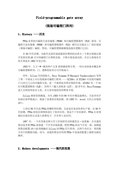
Field-programmable gate array(现场可编程门阵列)1、History ——历史FPGA业界的可编程只读存储器(PROM)和可编程逻辑器件(PLD)萌芽。
可编程只读存储器(PROM)和可编程逻辑器件(PLD)都可以分批在工厂或在现场(现场可编程)编程,然而,可编程逻辑被硬线连接在逻辑门之间。
在80年代末期,为海军水面作战部提供经费的的史蒂夫·卡斯尔曼提出要开发将实现60万可再编程门计算机实验。
卡斯尔曼是成功的,并且与系统有关的专利是在1992年发行的。
1985年,大卫·W·佩奇和卢文R.彼得森获得专利,一些行业的基本概念和可编程逻辑阵列,门,逻辑块技术公司开始成立。
同年,Xilinx共同创始人,Ross Freeman和Bernard Vonderschmitt发明了第一个商业上可行的现场可编程门阵列——XC2064。
该XC2064可实现可编程门与其它门之间可编程互连,是一个新的技术和市场的开端。
XC2064有一个64位可配置逻辑块(CLB),有两个三输入查找表(LUT)。
20多年后,Ross Freeman 进入全国发明家名人堂,名人堂对他的发明赞誉不绝。
Xilinx继续受到挑战,并从1985年到90年代中期迅速增长,当竞争对手如雨后春笋般成立,削弱了显著的市场份额。
到1993年,Actel大约占市场的18%。
上世纪90年代是FPGA的爆炸性时期,无论是在复杂性和生产量。
在90年代初期,FPGA的电信和网络进行了初步应用。
到这个十年结束时,FPGA行业领袖们以他们的方式进入消费电子,汽车和工业应用。
1997年,一个在苏塞克斯大学工作的研究员阿德里安·汤普森,合并遗传算法技术和FPGA来创建一个声音识别装置,使得FPGA的名气可见一斑。
汤姆逊的算法配置10×10的细胞在Xilinx的FPGA芯片阵列,以两个音区分,利用数字芯片的模拟功能。
一篇关于FPGA的英文文献及翻译-19页精选文档
使用LabVIEW FPGA模块开发可编程自动化控制器Building Programmable Automation Controllers with LabVIEW FPGA OverviewProgrammable Automation Controllers (PACs) are gaining acceptance within the industrial control market as the ideal solution for applications that require highly integrated analog and digital I/O, floating-point processing, and seamless connectivity to multiple processing nodes. National Instruments offers a variety of PAC solutions powered by one common software development environment, NI LabVIEW. With LabVIEW, you can build custom I/O interfaces for industrial applications using add-on software, such as the NI LabVIEW FPGA Module.With the LabVIEW FPGA Module and reconfigurable I/O (RIO) hardware, National Instruments delivers an intuitive, accessible solution for incorporating the flexibility and customizability of FPGA technology into industrial PAC systems. You can define the logic embedded in FPGA chips across the family of RIO hardware targets without knowing low-level hardware description languages (HDLs) or board-level hardware design details, as well as quickly define hardware for ultrahigh-speed control, customized timing and synchronization, low-level signal processing, and custom I/O with analog, digital, and counters within a single device. Youalso can integrate your custom NI RIO hardware with image acquisition and analysis, motion control, and industrial protocols, such as CAN and RS232, to rapidly prototype and implement a complete PAC system.Table of Contents1.Introduction2.NI RIO Hardware for PACs3.Building PACs with LabVIEW and the LabVIEW FPGA Module4.FPGA Development Flowing NI SoftMotion to Create Custom Motion Controllers6.Applications7.ConclusionIntroductionYou can use graphical programming in LabVIEW and the LabVIEW FPGA Module to configure the FPGA (field-programmable gate array) on NI RIO devices. RIO technology, the merging of LabVIEW graphical programming with FPGAs on NI RIO hardware, provides a flexible platform for creating sophisticated measurement and control systems that you could previously create only with custom-designed hardware.An FPGA is a chip that consists of many unconfigured logic gates. Unlike the fixed, vendor-defined functionality of an ASIC(application-specific integrated circuit) chip, you can configure and reconfigure the logic on FPGAs for your specific application. FPGAs are used in applications where either the cost of developing and fabricating an ASIC is prohibitive, or the hardware must be reconfigured after being placed into service. The flexible, software-programmable architecture of FPGAs offer benefits such as high-performance execution of custom algorithms, precise timing and synchronization, rapid decision making, and simultaneous execution of parallel tasks. Today, FPGAs appear in such devices as instruments, consumer electronics, automobiles, aircraft, copy machines, and application-specific computer hardware. While FPGAs are often used in industrial control products, FPGA functionality has not previously been made accessible to industrial control engineers. Defining FPGAs has historically required expertise using HDL programming or complex design tools used more by hardware design engineers than by control engineers.With the LabVIEW FPGA Module and NI RIO hardware, you now can use LabVIEW, a high-level graphical development environment designed specifically for measurement and control applications, to create PACs that have the customization, flexibility, and high-performance of FPGAs. Because the LabVIEW FPGA Module configures custom circuitry in hardware, your system can process and generate synchronized analog and digitalsignals rapidly and deterministically. Figure 1 illustrates many of the NI RIO devices that you can configure using the LabVIEW FPGA Module.Figure 1. LabVIEW FPGA VI Block Diagram and RIO Hardware Platforms NI RIO Hardware for PACsHistorically, programming FPGAs has been limited to engineers who have in-depth knowledge of VHDL or other low-level design tools, which require overcoming a very steep learning curve. With the LabVIEW FPGA Module, NI has opened FPGA technology to a broader set of engineers who can now define FPGA logic using LabVIEW graphical development. Measurement and control engineers can focus primarily on their test and control application, where their expertise lies, rather than the low-level semantics of transferring logic into the cells of the chip. The LabVIEW FPGA Module model works because of the tight integration between the LabVIEW FPGA Module and the commercial off-the-shelf (COTS) hardware architecture of the FPGA and surrounding I/O components.National Instruments PACs provide modular, off-the-shelf platforms for your industrial control applications. With the implementation of RIO technology on PCI, PXI, and Compact Vision System platforms and the introduction of RIO-based CompactRIO, engineers now have the benefits of a COTS platform with the high-performance, flexibility, and customizationbenefits of FPGAs at their disposal to build PACs. National Instruments PCI and PXI R Series plug-in devices provide analog and digital data acquisition and control for high-performance, user-configurable timing and synchronization, as well as onboard decision making on a single device. Using these off-the-shelf devices, you can extend your NI PXI or PCI industrial control system to include high-speed discrete and analog control, custom sensor interfaces, and precise timing and control.NI CompactRIO, a platform centered on RIO technology, provides a small, industrially rugged, modular PAC platform that gives you high-performance I/O and unprecedented flexibility in system timing. You can use NI CompactRIO to build an embedded system for applications such as in-vehicle data acquisition, mobile NVH testing, and embedded machine control systems. The rugged NI CompactRIO system is industrially rated and certified, and it is designed for greater than 50 g of shock at a temperature range of -40 to 70 °C.NI Compact Vision System is a rugged machine vision package that withstands the harsh environments common in robotics, automated test, and industrial inspection systems. NI CVS-145x devices offer unprecedented I/O capabilities and network connectivity for distributed machine vision applications.NI CVS-145x systems use IEEE 1394 (FireWire) technology, compatible with more than 40 cameras with a wide range of functionality,performance, and price. NI CVS-1455 and NI CVS-1456 devices contain configurable FPGAs so you can implement custom counters, timing, or motor control in your machine vision application.Building PACs with LabVIEW and the LabVIEW FPGA ModuleWith LabVIEW and the LabVIEW FPGA Module, you add significant flexibility and customization to your industrial control hardware. Because many PACs are already programmed using LabVIEW, programming FPGAs with LabVIEW is easy because it uses the same LabVIEW development environment. When you target the FPGA on an NI RIO device, LabVIEW displays only the functions that can be implemented in the FPGA, further easing the use of LabVIEW to program FPGAs. The LabVIEW FPGA Module Functions palette includes typical LabVIEW structures and functions, such as While Loops, For Loops, Case Structures, and Sequence Structures as well as a dedicated set of LabVIEW FPGA-specific functions for math, signal generation and analysis, linear and nonlinear control, comparison logic, array and cluster manipulation, occurrences, analog and digital I/O, and timing. You can use a combination of these functions to define logic and embed intelligence onto your NI RIO device.Figure 2 shows an FPGA application that implements a PID control algorithm on the NI RIO hardware and a host application on a Windows machine or an RT target that communicates with the NI RIO hardware. Thisapplication reads from analog input 0 (AI0), performs the PID calculation, and outputs the resulting data on analog output 0 (AO0). While the FPGA clock runs at 40 MHz the loop in this example runs much slower because each component takes longer than one-clock cycle to execute. Analog control loops can run on an FPGA at a rate of about 200 kHz. You can specify the clock rate at compile time. This example shows only one PID loop; however, creating additional functionality on the NI RIO device is merely a matter of adding another While Loop. Unlike traditional PC processors, FPGAs are parallel processors. Adding additional loops to your application does not affect the performance of your PID loop.Figure 2. PID Control Using an Embedded LabVIEW FPGA VI withCorresponding LabVIEW Host VI.FPGA Development FlowAfter you create the LabVIEW FPGA VI, you compile the code to run on the NI RIO hardware. Depending on the complexity of your code and the specifications of your development system, compile time for an FPGA VI can range from minutes to several hours. To maximize development productivity, with the R Series RIO devices you can use a bit-accurate emulation mode so you can verify the logic of your design before initiating the compile process. When you target the FPGA Device Emulator, LabVIEW accesses I/O from the device and executes the VI logic on the Windowsdevelopment computer. In this mode, you can use the same debugging tools available in LabVIEW for Windows, such as execution highlighting, probes, and breakpoints.Once the LabVIEW FPGA code is compiled, you create a LabVIEW host VI to integrate your NI RIO hardware into the rest of your PAC system. Figure 3 illustrates the development process for creating an FPGA application. The host VI uses controls and indicators on the FPGA VI front panel to transfer data between the FPGA on the RIO device and the host processing engine. These front panel objects are represented as data registers within the FPGA. The host computer can be either a PC or PXI controller running Windows or a PC, PXI controller, Compact Vision System, or CompactRIO controller running a real-time operating system (RTOS). In the above example, we exchange the set point, PID gains, loop rate, AI0, and AO0 data with the LabVIEW host VI.Figure 3. LabVIEW FPGA Development FlowThe NI RIO device driver includes a set of functions to develop a communication interface to the FPGA. The first step in building a host VI is to open a reference to the FPGA VI and RIO device. The Open FPGA VI Reference function, as seen in Figure 2, also downloads and runs the compiled FPGA code during execution. After opening the reference, you read and write to the control and indicator registers on the FPGA using theRead/Write Control function. Once you wire the FPGA reference into this function, you can simply select which controls and indicators you want to read and write to. You can enclose the FPGA Read/Write function within a While Loop to continuously read and write to the FPGA. Finally, the last function within the LabVIEW host VI in Figure 2 is the Close FPGA VI Reference function. The Close FPGA VI Reference function stops the FPGA VI and closes the reference to the device. Now you can download other compiled FPGA VIs to the device to change or modify its functionality.The LabVIEW host VI can also be used to perform floating-point calculations, data logging, networking, and any calculations that do not fit within the FPGA fabric. For added determinism and reliability, you can run your host application on an RTOS with the LabVIEW Real-Time Module. LabVIEW Real-Time systems provide deterministic processing engines for functions performed synchronously or asynchronously to the FPGA. For example, floating-point arithmetic, including FFTs, PID calculations, and custom control algorithms, are often performed in the LabVIEW Real-Time environment. Relevant data can be stored on a LabVIEW Real-Time system or transferred to a Windows host computer for off-line analysis, data logging, or user interface displays. The architecture for this configuration is shown in Figure 4. Each NI PAC platform that offers RIO hardware can run LabVIEW Real-Time VIs.Figure 4. Complete PAC Architecture Using LabVIEW FPGA, LabVIEW Real-Timeand Host PCWithin each R Series and CompactRIO device, there is flash memory available to store a compiled LabVIEW FPGA VI and run the application immediately upon power up of the device. In this configuration, as long as the FPGA has power, it runs the FPGA VI, even if the host computer crashes or is powered down. This is ideal for programming safety power down and power up sequences when unexpected events occur.Using NI SoftMotion to Create Custom Motion ControllersThe NI SoftMotion Development Module for LabVIEW provides VIs and functions to help you build custom motion controllers as part of NI PAC hardware platforms that can include NI RIO devices, DAQ devices, and Compact FieldPoint. NI SoftMotion provides all of the functions that typically reside on a motion controller DSP. With it, you can handle path planning, trajectory generation, and position and velocity loop control in the NI LabVIEW environment and then deploy the code on LabVIEW Real-Time or LabVIEW FPGA-based target hardware.NI SoftMotion includes functions for trajectory generator and spline engine and examples with complete source code for supervisory control, position, and velocity control loop using the PID algorithm. Supervisory control and the trajectory generator run on a LabVIEW Real-Time target and run at millisecond loop rates. The spline engine and the control loop can run either on a LabVIEW Real-Time target at millisecond loop rates or on a LabVIEW FPGA target at microsecond loop rates.ApplicationsBecause the LabVIEW FPGA Module can configure low-level hardware design of FPGAs and use the FPGAs within in a modular system, it is ideal for industrial control applications requiring custom hardware. These custom applications can include a custom mix of analog, digital, and counter/timer I/O, analog control up to 125 kHz, digital control up to 20 MHz, and interfacing to custom digital protocols for the following:•Batch control•Discrete control•Motion control•In-vehicle data acquisition•Machine condition monitoring•Rapid control prototyping (RCP)•Industrial control and acquisition•Distributed data acquisition and control•Mobile/portable noise, vibration, and harshness (NVH) analysisConclusionThe LabVIEW FPGA Module brings the flexibility, performance, and customization of FPGAs to PAC platforms. Using NI RIO devices and LabVIEW graphical programming, you can build flexible and custom hardware using the COTS hardware often required in industrial control applications. Because you are using LabVIEW, a programming language already used in many industrial control applications, to define your NI RIO hardware, there is no need to learn VHDL or other low-level hardware design tools to create custom hardware. Using the LabVIEW FPGA Module and NI RIO hardware as part of your NI PAC adds significant flexibility and functionality for applications requiring ultrahigh-speed control, interfaces to custom digital protocols, or a custom I/O mix of analog, digital, and counters.使用LabVIEW FPGA(现场可编程门阵列)模块开发可编程自动化控制器综述工业控制上的应用要求高度集成的模拟和数字输入输出、浮点运算和多重处理节点的无缝连接。
英文文献及翻译(FPGA)
Building Programmable Automation Controllers with LabVIEWFPGAOverviewProgrammable Automation Controllers (PACs) are gaining acceptance within the industrial control market as the ideal solution for applications that require highly integrated analog and digital I/O, floating-point processing, and seamless connectivity to multiple processing nodes. National Instruments offers a variety of PAC solutions powered by one common software development environment, NI LabVIEW. With LabVIEW, you can build custom I/O interfaces for industrial applications using add-on software, such as the NI LabVIEW FPGA Module.With the LabVIEW FPGA Module and reconfigurable I/O (RIO) hardware, National Instruments delivers an intuitive, accessible solution for incorporating the flexibility and customizability of FPGA technology into industrial PAC systems. You can define the logic embedded in FPGA chips across the family of RIO hardware targets without knowinglow-level hardware description languages (HDLs) or board-level hardware design details, as well as quickly define hardware for ultrahigh-speed control, customized timing and synchronization, low-level signal processing, and custom I/O with analog, digital, and counters within a single device. You also can integrate your custom NI RIO hardware with image acquisition and analysis, motion control, and industrial protocols, such as CAN and RS232, to rapidly prototype and implement a complete PAC system.Table of Contents1.Introduction2.NI RIO Hardware for PACs3.Building PACs with LabVIEW and the LabVIEW FPGA Module4.FPGA Development Flowing NI SoftMotion to Create Custom Motion Controllers6.Applications7.ConclusionIntroductionYou can use graphical programming in LabVIEW and the LabVIEW FPGA Module to configure the FPGA (field-programmable gate array) on NI RIO devices. RIO technology, the merging of LabVIEW graphical programming with FPGAs on NI RIO hardware, provides a flexible platform for creating sophisticated measurement and control systems that you could previously create only with custom-designed hardware.An FPGA is a chip that consists of many unconfigured logic gates. Unlike the fixed, vendor-defined functionality of an ASIC (application-specific integrated circuit) chip, you can configure and reconfigure the logic on FPGAs for your specific application. FPGAs are used in applications where either the cost of developing and fabricating an ASIC is prohibitive, or the hardware must be reconfigured after being placed into service. The flexible, software-programmable architecture of FPGAs offer benefits such ashigh-performance execution of custom algorithms, precise timing and synchronization, rapid decision making, and simultaneous execution of parallel tasks. Today, FPGAs appear in such devices as instruments, consumer electronics, automobiles, aircraft, copy machines, and application-specific computer hardware. While FPGAs are often used in industrial control products, FPGA functionality has not previously been made accessible to industrial control engineers. Defining FPGAs has historically required expertise using HDL programming or complex design tools used more by hardware design engineers than by control engineers.With the LabVIEW FPGA Module and NI RIO hardware, you now can use LabVIEW, a high-level graphical development environment designed specifically for measurement and control applications, to create PACs that have the customization, flexibility, andhigh-performance of FPGAs. Because the LabVIEW FPGA Module configures custom circuitry in hardware, your system can process and generate synchronized analog and digital signals rapidly and deterministically.NI RIO Hardware for PACsHistorically, programming FPGAs has been limited to engineers who have in-depth knowledge of VHDL or other low-level design tools, which require overcoming a very steep learning curve. With the LabVIEW FPGA Module, NI has opened FPGA technology to a broader set of engineers who can now define FPGA logic using LabVIEW graphical development. Measurement and control engineers can focus primarily on their test and control application, where their expertise lies, rather than the low-level semantics oftransferring logic into the cells of the chip. The LabVIEW FPGA Module model works because of the tight integration between the LabVIEW FPGA Module and the commercial off-the-shelf (COTS) hardware architecture of the FPGA and surrounding I/O components.National Instruments PACs provide modular, off-the-shelf platforms for your industrial control applications. With the implementation of RIO technology on PCI, PXI, and Compact Vision System platforms and the introduction of RIO-based CompactRIO, engineers now have the benefits of a COTS platform with the high-performance, flexibility, and customization benefits of FPGAs at their disposal to build PACs. National Instruments PCI and PXI R Series plug-in devices provide analog and digital data acquisition and control for high-performance, user-configurable timing and synchronization, as well as onboard decision making on a single device. Using these off-the-shelf devices, you can extend your NI PXI or PCI industrial control system to include high-speed discrete and analog control, custom sensor interfaces, and precise timing and control.NI CompactRIO, a platform centered on RIO technology, provides a small, industrially rugged, modular PAC platform that gives you high-performance I/O and unprecedented flexibility in system timing. You can use NI CompactRIO to build an embedded system for applications such as in-vehicle data acquisition, mobile NVH testing, and embedded machine control systems. The rugged NI CompactRIO system is industrially rated and certified, and it is designed for greater than 50 g of shock at a temperature range of -40 to 70 °C.NI Compact Vision System is a rugged machine vision package that withstands the harsh environments common in robotics, automated test, and industrial inspection systems. NI CVS-145x devices offer unprecedented I/O capabilities and network connectivity for distributed machine vision applications.NI CVS-145x systems use IEEE 1394 (FireWire) technology, compatible with more than 40 cameras with a wide range of functionality, performance, and price. NI CVS-1455 and NI CVS-1456 devices contain configurable FPGAs so you can implement custom counters, timing, or motor control in your machine vision application.Building PACs with LabVIEW and the LabVIEW FPGA ModuleWith LabVIEW and the LabVIEW FPGA Module, you add significant flexibility and customization to your industrial control hardware. Because many PACs are alreadyprogrammed using LabVIEW, programming FPGAs with LabVIEW is easy because it uses the same LabVIEW development environment. When you target the FPGA on an NI RIO device, LabVIEW displays only the functions that can be implemented in the FPGA, further easing the use of LabVIEW to program FPGAs. The LabVIEW FPGA Module Functions palette includes typical LabVIEW structures and functions, such as While Loops, For Loops, Case Structures, and Sequence Structures as well as a dedicated set of LabVIEW FPGA-specific functions for math, signal generation and analysis, linear and nonlinear control, comparison logic, array and cluster manipulation, occurrences, analog and digital I/O, and timing. You can use a combination of these functions to define logic and embed intelligence onto your NI RIO device.This application reads from analog input 0 (AI0), performs the PID calculation, and outputs the resulting data on analog output 0 (AO0). While the FPGA clock runs at 40 MHz the loop in this example runs much slower because each component takes longer than one-clock cycle to execute. Analog control loops can run on an FPGA at a rate of about 200 kHz. You can specify the clock rate at compile time. This example shows only one PID loop; however, creating additional functionality on the NI RIO device is merely a matter of adding another While Loop. Unlike traditional PC processors, FPGAs are parallel processors. Adding additional loops to your application does not affect the performance of your PID loop.FPGA Development FlowAfter you create the LabVIEW FPGA VI, you compile the code to run on the NI RIO hardware. Depending on the complexity of your code and the specifications of your development system, compile time for an FPGA VI can range from minutes to several hours. To maximize development productivity, with the R Series RIO devices you can use a bit-accurate emulation mode so you can verify the logic of your design before initiating the compile process. When you target the FPGA Device Emulator, LabVIEW accesses I/O from the device and executes the VI logic on the Windows development computer. In this mode, you can use the same debugging tools available in LabVIEW for Windows, such as execution highlighting, probes, and breakpoints.Once the LabVIEW FPGA code is compiled, you create a LabVIEW host VI to integrate your NI RIO hardware into the rest of your PAC system. The host VI uses controls and indicators on the FPGA VI front panel to transfer data between the FPGA onthe RIO device and the host processing engine. These front panel objects are represented as data registers within the FPGA. The host computer can be either a PC or PXI controller running Windows or a PC, PXI controller, Compact Vision System, or CompactRIO controller running a real-time operating system (RTOS). In the above example, we exchange the set point, PID gains, loop rate, AI0, and AO0 data with the LabVIEW host VI.The NI RIO device driver includes a set of functions to develop a communication interface to the FPGA. The first step in building a host VI is to open a reference to the FPGA VI and RIO device. The Open FPGA VI Reference function, also downloads and runs the compiled FPGA code during execution. After opening the reference, you read and write to the control and indicator registers on the FPGA using the Read/Write Control function. Once you wire the FPGA reference into this function, you can simply select which controls and indicators you want to read and write to. You can enclose the FPGA Read/Write function within a While Loop to continuously read and write to the FPGA. Finally, the last function within the LabVIEW host VI is the Close FPGA VI Reference function. The Close FPGA VI Reference function stops the FPGA VI and closes the reference to the device. Now you can download other compiled FPGA VIs to the device to change or modify its functionality.The LabVIEW host VI can also be used to perform floating-point calculations, data logging, networking, and any calculations that do not fit within the FPGA fabric. For added determinism and reliability, you can run your host application on an RTOS with the LabVIEW Real-Time Module. LabVIEW Real-Time systems provide deterministic processing engines for functions performed synchronously or asynchronously to the FPGA. For example, floating-point arithmetic, including FFTs, PID calculations, and custom control algorithms, are often performed in the LabVIEW Real-Time environment. Relevant data can be stored on a LabVIEW Real-Time system or transferred to a Windows host computer for off-line analysis, data logging, or user interface displays. The architecture for this configuration . Each NI PAC platform that offers RIO hardware can run LabVIEW Real-Time VIs.Within each R Series and CompactRIO device, there is flash memory available to store a compiled LabVIEW FPGA VI and run the application immediately upon power up of the device. In this configuration, as long as the FPGA has power, it runs the FPGA VI,even if the host computer crashes or is powered down. This is ideal for programming safety power down and power up sequences when unexpected events occur.Using NI SoftMotion to Create Custom Motion ControllersThe NI SoftMotion Development Module for LabVIEW provides VIs and functions to help you build custom motion controllers as part of NI PAC hardware platforms that can include NI RIO devices, DAQ devices, and Compact FieldPoint. NI SoftMotion provides all of the functions that typically reside on a motion controller DSP. With it, you can handle path planning, trajectory generation, and position and velocity loop control in the NI LabVIEW environment and then deploy the code on LabVIEW Real-Time or LabVIEW FPGA-based target hardware.NI SoftMotion includes functions for trajectory generator and spline engine and examples with complete source code for supervisory control, position, and velocity control loop using the PID algorithm. Supervisory control and the trajectory generator run on a LabVIEW Real-Time target and run at millisecond loop rates. The spline engine and the control loop can run either on a LabVIEW Real-Time target at millisecond loop rates or on a LabVIEW FPGA target at microsecond loop rates.ApplicationsBecause the LabVIEW FPGA Module can configure low-level hardware design of FPGAs and use the FPGAs within in a modular system, it is ideal for industrial control applications requiring custom hardware. These custom applications can include a custom mix of analog, digital, and counter/timer I/O, analog control up to 125 kHz, digital control up to 20 MHz, and interfacing to custom digital protocols for the following:∙Batch control∙Discrete control∙Motion control∙In-vehicle data acquisition∙Machine condition monitoring∙Rapid control prototyping (RCP)∙Industrial control and acquisition∙Distributed data acquisition and controlMobile/portable noise, vibration, and harshness (NVH) analysis ConclusionThe LabVIEW FPGA Module brings the flexibility, performance, and customization of FPGAs to PAC platforms. Using NI RIO devices and LabVIEW graphical programming, you can build flexible and custom hardware using the COTS hardware often required in industrial control applications. Because you are using LabVIEW, a programming language already used in many industrial control applications, to define your NI RIO hardware, there is no need to learn VHDL or other low-level hardware design tools to create custom hardware. Using the LabVIEW FPGA Module and NI RIO hardware as part of your NI PAC adds significant flexibility and functionality for applications requiringultrahigh-speed control, interfaces to custom digital protocols, or a custom I/O mix of analog, digital, and counters.使用LabVIEW FPGA(现场可编程门阵列)模块开发可编程自动化控制器综述工业控制上的应用要求高度集成的模拟和数字输入输出、浮点运算和多重处理节点的无缝连接。
一篇关于FPGA的英文文献及翻译12页word
使用LabVIEW FPGA模块开发可编程自动化控制器Building Programmable Automation Controllers with LabVIEWFPGAOverviewProgrammable Automation Controllers (PACs) are gaining acceptance within the industrial control market as the ideal solution for applications that require highly integrated analog and digital I/O, floating-point processing, and seamless connectivity to multiple processing nodes. National Instruments offers a variety of PAC solutions powered by one common software development environment, NI LabVIEW. With LabVIEW, you can build custom I/O interfaces for industrial applications using add-on software, such as the NI LabVIEW FPGA Module.With the LabVIEW FPGA Module and reconfigurable I/O (RIO) hardware, National Instruments delivers an intuitive, accessible solution for incorporating the flexibility and customizability of FPGA technology into industrial PAC systems. You can define the logic embedded in FPGA chips across the family of RIO hardware targets without knowing low-level hardware description languages (HDLs) or board-level hardware design details, as well as quickly define hardware for ultrahigh-speed control, customized timing and synchronization, low-level signal processing, and custom I/O with analog, digital, and counters within a single device. You also can integrate your custom NI RIO hardware with image acquisition and analysis, motion control, and industrial protocols, such as CAN and RS232, to rapidly prototype and implement a complete PAC system.Table of Contents1.Introduction2.NI RIO Hardware for PACs3.Building PACs with LabVIEW and the LabVIEW FPGA Module4.FPGA Development Flowing NI SoftMotion to Create Custom Motion Controllers6.Applications7.ConclusionIntroductionYou can use graphical programming in LabVIEW and the LabVIEW FPGA Module to configure the FPGA (field-programmable gate array) on NI RIO devices. RIO technology, the merging of LabVIEW graphical programming with FPGAs on NI RIO hardware, provides a flexible platform for creating sophisticated measurement and control systems that you could previously create only with custom-designed hardware.An FPGA is a chip that consists of many unconfigured logic gates. Unlike the fixed, vendor-defined functionality of an ASIC (application-specific integrated circuit) chip, you can configure and reconfigure the logic on FPGAs for your specific application. FPGAs are used in applications where either the cost of developing and fabricating an ASIC is prohibitive, or the hardware must be reconfigured after being placed into service. The flexible,software-programmable architecture of FPGAs offer benefits such as high-performance execution of custom algorithms, precise timing and synchronization, rapid decision making, and simultaneous execution of parallel tasks. Today, FPGAs appear in such devices as instruments, consumer electronics, automobiles, aircraft, copy machines, andapplication-specific computer hardware. While FPGAs are often used in industrial control products, FPGA functionality has not previously been made accessible to industrial control engineers. Defining FPGAs has historically required expertise using HDL programming or complex design tools used more by hardware design engineers than by control engineers.With the LabVIEW FPGA Module and NI RIO hardware, you now can use LabVIEW, a high-level graphical development environment designed specifically for measurement and control applications, to create PACs that have the customization, flexibility, andhigh-performance of FPGAs. Because the LabVIEW FPGA Module configures custom circuitry in hardware, your system can process and generate synchronized analog and digital signals rapidly and deterministically. Figure 1 illustrates many of the NI RIO devices that you can configure using the LabVIEW FPGA Module.Figure 1. LabVIEW FPGA VI Block Diagram and RIO Hardware PlatformsNI RIO Hardware for PACsHistorically, programming FPGAs has been limited to engineers who have in-depth knowledge of VHDL or other low-level design tools, which require overcoming a very steep learning curve. With the LabVIEW FPGA Module, NI has opened FPGA technology to a broader set of engineers who can now define FPGA logic using LabVIEW graphical development. Measurement and control engineers can focus primarily on their test and control application, where their expertise lies, rather than the low-level semantics of transferring logic into the cells of the chip. The LabVIEW FPGA Module model works because of the tight integration between the LabVIEW FPGA Module and the commercial off-the-shelf (COTS) hardware architecture of the FPGA and surrounding I/O components.National Instruments PACs provide modular, off-the-shelf platforms for your industrial control applications. With the implementation of RIO technology on PCI, PXI, and Compact Vision System platforms and the introduction of RIO-based CompactRIO, engineers now have the benefits of a COTS platform with the high-performance, flexibility, and customization benefits of FPGAs at their disposal to build PACs. National Instruments PCI and PXI R Series plug-in devices provide analog and digital data acquisition and control for high-performance, user-configurable timing and synchronization, as well as onboard decision making on a single device. Using these off-the-shelf devices, you can extend your NI PXI or PCI industrial control system to include high-speed discrete and analog control, custom sensor interfaces, and precise timing and control.NI CompactRIO, a platform centered on RIO technology, provides a small, industrially rugged, modular PAC platform that gives you high-performance I/O and unprecedented flexibility in system timing. You can use NI CompactRIO to build an embedded system for applications such as in-vehicle data acquisition, mobile NVH testing, and embedded machine control systems. The rugged NI CompactRIO system is industrially rated and certified, and it is designed for greater than 50 g of shock at a temperature range of -40 to 70 °C.NI Compact Vision System is a rugged machine vision package that withstands the harsh environments common in robotics, automated test, and industrial inspection systems. NICVS-145x devices offer unprecedented I/O capabilities and network connectivity for distributed machine vision applications.NI CVS-145x systems use IEEE 1394 (FireWire) technology, compatible with more than 40 cameras with a wide range of functionality, performance, and price. NI CVS-1455 and NI CVS-1456 devices contain configurable FPGAs so you can implement custom counters, timing, or motor control in your machine vision application.Building PACs with LabVIEW and the LabVIEW FPGA Module With LabVIEW and the LabVIEW FPGA Module, you add significant flexibility and customization to your industrial control hardware. Because many PACs are already programmed using LabVIEW, programming FPGAs with LabVIEW is easy because it uses the same LabVIEW development environment. When you target the FPGA on an NI RIO device, LabVIEW displays only the functions that can be implemented in the FPGA, further easing the use of LabVIEW to program FPGAs. The LabVIEW FPGA Module Functions palette includes typical LabVIEW structures and functions, such as While Loops, For Loops, Case Structures, and Sequence Structures as well as a dedicated set of LabVIEWFPGA-specific functions for math, signal generation and analysis, linear and nonlinear control, comparison logic, array and cluster manipulation, occurrences, analog and digital I/O, and timing. You can use a combination of these functions to define logic and embed intelligence onto your NI RIO device.Figure 2 shows an FPGA application that implements a PID control algorithm on the NI RIO hardware and a host application on a Windows machine or an RT target thatcommunicates with the NI RIO hardware. This application reads from analog input 0 (AI0), performs the PID calculation, and outputs the resulting data on analog output 0 (AO0). While the FPGA clock runs at 40 MHz the loop in this example runs much slower because each component takes longer than one-clock cycle to execute. Analog control loops can run on an FPGA at a rate of about 200 kHz. You can specify the clock rate at compile time. This example shows only one PID loop; however, creating additional functionality on the NI RIO device is merely a matter of adding another While Loop. Unlike traditional PC processors, FPGAs are parallel processors. Adding additional loops to your application does not affect the performance of your PID loop.Figure 2. PID Control Using an Embedded LabVIEW FPGA VI with Corresponding LabVIEW HostVI.FPGA Development FlowAfter you create the LabVIEW FPGA VI, you compile the code to run on the NI RIO hardware. Depending on the complexity of your code and the specifications of your development system, compile time for an FPGA VI can range from minutes to several hours. To maximize development productivity, with the R Series RIO devices you can use abit-accurate emulation mode so you can verify the logic of your design before initiating the compile process. When you target the FPGA Device Emulator, LabVIEW accesses I/O from the device and executes the VI logic on the Windows development computer. In this mode, you can use the same debugging tools available in LabVIEW for Windows, such as execution highlighting, probes, and breakpoints.Once the LabVIEW FPGA code is compiled, you create a LabVIEW host VI to integrate your NI RIO hardware into the rest of your PAC system. Figure 3 illustrates the development process for creating an FPGA application. The host VI uses controls and indicators on the FPGA VI front panel to transfer data between the FPGA on the RIO device and the host processing engine. These front panel objects are represented as data registers within the FPGA. The host computer can be either a PC or PXI controller running Windows or a PC, PXI controller, Compact Vision System, or CompactRIO controller running a real-time operating system (RTOS). In the above example, we exchange the set point, PID gains, loop rate, AI0, and AO0 data with the LabVIEW host VI.Figure 3. LabVIEW FPGA Development FlowThe NI RIO device driver includes a set of functions to develop a communication interface to the FPGA. The first step in building a host VI is to open a reference to the FPGA VI and RIO device. The Open FPGA VI Reference function, as seen in Figure 2, also downloads and runs the compiled FPGA code during execution. After opening the reference, you read and write to the control and indicator registers on the FPGA using the Read/Write Control function. Once you wire the FPGA reference into this function, you can simply select which controls and indicators you want to read and write to. You can enclose the FPGARead/Write function within a While Loop to continuously read and write to the FPGA. Finally, the last function within the LabVIEW host VI in Figure 2 is the Close FPGA VI Reference function. The Close FPGA VI Reference function stops the FPGA VI and closes the reference to the device. Now you can download other compiled FPGA VIs to the device to change or modify its functionality.The LabVIEW host VI can also be used to perform floating-point calculations, data logging, networking, and any calculations that do not fit within the FPGA fabric. For added determinism and reliability, you can run your host application on an RTOS with the LabVIEW Real-Time Module. LabVIEW Real-Time systems provide deterministic processing engines for functions performed synchronously or asynchronously to the FPGA. For example, floating-point arithmetic, including FFTs, PID calculations, and custom control algorithms, are often performed in the LabVIEW Real-Time environment. Relevant data can be stored on a LabVIEW Real-Time system or transferred to a Windows host computer for off-line analysis, data logging, or user interface displays. The architecture for this configuration is shown in Figure 4. Each NI PAC platform that offers RIO hardware can run LabVIEW Real-Time VIs.Figure 4. Complete PAC Architecture Using LabVIEW FPGA, LabVIEW Real-Time and Host PC Within each R Series and CompactRIO device, there is flash memory available to store a compiled LabVIEW FPGA VI and run the application immediately upon power up of the device. In this configuration, as long as the FPGA has power, it runs the FPGA VI, even if the host computer crashes or is powered down. This is ideal for programming safety power down and power up sequences when unexpected events occur.Using NI SoftMotion to Create Custom Motion ControllersThe NI SoftMotion Development Module for LabVIEW provides VIs and functions to help you build custom motion controllers as part of NI PAC hardware platforms that can include NI RIO devices, DAQ devices, and Compact FieldPoint. NI SoftMotion provides all of the functions that typically reside on a motion controller DSP. With it, you can handle path planning, trajectory generation, and position and velocity loop control in the NI LabVIEW environment and then deploy the code on LabVIEW Real-Time or LabVIEW FPGA-based target hardware.NI SoftMotion includes functions for trajectory generator and spline engine and examples with complete source code for supervisory control, position, and velocity controlloop using the PID algorithm. Supervisory control and the trajectory generator run on a LabVIEW Real-Time target and run at millisecond loop rates. The spline engine and the control loop can run either on a LabVIEW Real-Time target at millisecond loop rates or on a LabVIEW FPGA target at microsecond loop rates.ApplicationsBecause the LabVIEW FPGA Module can configure low-level hardware design of FPGAs and use the FPGAs within in a modular system, it is ideal for industrial control applications requiring custom hardware. These custom applications can include a custom mix of analog, digital, and counter/timer I/O, analog control up to 125 kHz, digital control up to 20 MHz, and interfacing to custom digital protocols for the following:∙Batch control∙Discrete control∙Motion control∙In-vehicle data acquisition∙Machine condition monitoring∙Rapid control prototyping (RCP)∙Industrial control and acquisition∙Distributed data acquisition and control∙Mobile/portable noise, vibration, and harshness (NVH) analysis ConclusionThe LabVIEW FPGA Module brings the flexibility, performance, and customization of FPGAs to PAC platforms. Using NI RIO devices and LabVIEW graphical programming, you can build flexible and custom hardware using the COTS hardware often required in industrial control applications. Because you are using LabVIEW, a programming language already used in many industrial control applications, to define your NI RIO hardware, there is no need to learn VHDL or other low-level hardware design tools to create custom hardware. Using the LabVIEW FPGA Module and NI RIO hardware as part of your NI PAC adds significant flexibility and functionality for applications requiring ultrahigh-speed control, interfaces to custom digital protocols, or a custom I/O mix of analog, digital, and counters.使用LabVIEW FPGA(现场可编程门阵列)模块开发可编程自动化控制器综述工业控制上的应用要求高度集成的模拟和数字输入输出、浮点运算和多重处理节点的无缝连接。
- 1、下载文档前请自行甄别文档内容的完整性,平台不提供额外的编辑、内容补充、找答案等附加服务。
- 2、"仅部分预览"的文档,不可在线预览部分如存在完整性等问题,可反馈申请退款(可完整预览的文档不适用该条件!)。
- 3、如文档侵犯您的权益,请联系客服反馈,我们会尽快为您处理(人工客服工作时间:9:00-18:30)。
Field-programmable gate array(现场可编程门阵列)1、History ——历史FPGA业界的可编程只读存储器(PROM)和可编程逻辑器件(PLD)萌芽。
可编程只读存储器(PROM)和可编程逻辑器件(PLD)都可以分批在工厂或在现场(现场可编程)编程,然而,可编程逻辑被硬线连接在逻辑门之间。
在80年代末期,为海军水面作战部提供经费的的史蒂夫·卡斯尔曼提出要开发将实现60万可再编程门计算机实验。
卡斯尔曼是成功的,并且与系统有关的专利是在1992年发行的。
1985年,大卫·W·佩奇和卢文R.彼得森获得专利,一些行业的基本概念和可编程逻辑阵列,门,逻辑块技术公司开始成立。
同年,Xilinx共同创始人,Ross Freeman和Bernard Vonderschmitt发明了第一个商业上可行的现场可编程门阵列——XC2064。
该XC2064可实现可编程门与其它门之间可编程互连,是一个新的技术和市场的开端。
XC2064有一个64位可配置逻辑块(CLB),有两个三输入查找表(LUT)。
20多年后,Ross Freeman进入全国发明家名人堂,名人堂对他的发明赞誉不绝。
Xilinx继续受到挑战,并从1985年到90年代中期迅速增长,当竞争对手如雨后春笋般成立,削弱了显著的市场份额。
到1993年,Actel大约占市场的18%。
上世纪90年代是FPGA的爆炸性时期,无论是在复杂性和生产量。
在90年代初期,FPGA的电信和网络进行了初步应用。
到这个十年结束时,FPGA行业领袖们以他们的方式进入消费电子,汽车和工业应用。
1997年,一个在苏塞克斯大学工作的研究员阿德里安·汤普森,合并遗传算法技术和FPGA来创建一个声音识别装置,使得FPGA的名气可见一斑。
汤姆逊的算法配置10×10的细胞在Xilinx的FPGA芯片阵列,以两个音区分,利用数字芯片的模拟功能。
而今,该遗传算法应用到FPGA中设备的配置上被称为演化硬件。
2、Modern developments ——现代的发展最近的趋势是通过组合逻辑块和嵌入式微处理器和相关外设传统的FPGA 互连,形成一个完整的“可编程片上系统”,采取粗粒度的架构方法实现了这一步。
这项工作反映了由宝来先进系统集团的Ron Perlof 和Hana Potash在单一芯片SB24上结合可重构CPU架构的体系结构。
这项工作是在1982年完成的,这种混合动力技术可以在Xilinx公司的Virtex-II Pro和Virtex-4设备中看到,包括嵌入式FPGA的逻辑结构中的一个或多个PowerPC处理器。
Atmel 的FPSLIC是另一个这样的设备,它使用的是组合了Atmel可编程逻辑架构的AVR处理器。
Actel的SmartFusion器件集成了配置有Cortex-M3硬处理器内核(最大闪存和512KB为64KB RAM)的ARM架构和模拟外设,如多通道ADC和DAC的基于闪存的FPGA架构。
使用硬宏处理器的另一种方法是利用在FPGA逻辑中实现的软核处理器。
正如前面提到的,许多现代的FPGA对于“运行时间”必须拥有重新编程的能力,这就引导一个想法:可重构计算或可重构系统- CPU,可以重新配置自己以适应手头的任务。
Mitrionics公司的Mitrion虚拟处理器是可重构软处理器在FPGA中实现的一个例子。
然而,它并不支持在运行时动态重新配置,而是本身适应一个特定的程序。
此外,新的非FPGA架构开始出现。
软件可配置的微处理器,如拉伸S5000通过在同一芯片上提供处理器内核和FPGA状可编程内核的阵列采用一种混合方法。
3、FPGA comparisons ——FPGA的比较从历史上看,比起比自己稳定的ASIC同行,FPGA速度较慢,更节能,一般能达到的功能较少。
一项研究表明,设计在FPGA上实现需要平均18倍的面积,7倍的动态功耗,并且比相应的ASIC实现慢3倍。
Altera公司的Cyclone II FPGA,在一个Altera teraSIC 的DE1原型开发板上。
优点包括在现场修复错误,并可能包括向市场推出了较短的时间和较低的非经常性工程成本重新编程的能力。
供应商还可以通过开发自己的普通的FPGA 硬件中间道路,但它是制造最终版本,因此在设计已经被提交后它不可再进行修改。
Xilinx提供了一些市场和技术动态特性发生变化的ASIC / FPGA范例:●集成电路的成本都在积极上涨●ASIC的复杂性已经延长了开发时间●研发资源和员工人数在下降●缓慢推向市场的收入损失正在增加●经济不景气的财政限制正在推动低成本技术较于比以往较高的批量使用,这些趋势都使得FPGA比起ASIC是一个更好的选择。
一些FPGA有部分重新配置的功能,即让设备的一部分进行重新编程而其他部分继续运行。
4、Versus complex programmable logic devices ——复杂可编程逻辑器件CPLD(复杂可编程逻辑器件)和FPGA之间的主要区别是体系结构。
CPLD 具有由一个或多个可编程求和的副产物逻辑阵列供给相对少量的计时寄存器的稍微限制性结构。
这样做的结果是较少的灵活性,具有更可预测的定时延迟的优点和较高逻辑到互连比率。
FPGA架构,在另一方面,是由互连支配的。
这使得它们更灵活(在这对于在其中执行实际设计的范围而言),而且还能支持更复杂的设计。
CPLD和FPGA之间的另一个显着的区别是大多数FPGA中更高级别的嵌入式功能(诸如加法器和乘法器)和嵌入式存储器的存在,以及具有逻辑块实施解码器或数学函数的功能。
5、Applications ——应用FPGA中的应用包括数字信号处理,软件定义无线电,航空航天和国防系统,ASIC原型设计,医学成像,计算机视觉,语音识别,密码学,生物信息学,计算机硬件仿真,射电天文学,金属检测和范围日益扩大其他领域。
FPGA的最初开始于作为竞争对手的CPLD并参加了一个类似的空间,胶水的逻辑电路板。
由于其规模,能力和速度提高,在一些现在作为全系统销售状态下他们开始接手越来越大功能的芯片(SoC)。
特别是在90年代末引进专用乘法器进入FPGA架构,传统上的DSP的唯一储备应用将开始用FPGA的来代替。
FPGA可以利用其架构提供的大规模并行应用程序经常能再任何区域或算法中应用到,。
其中一个领域是密码破译,尤其是强力攻击的加密算法。
FPGA越来越多地传统的高性能计算应用程序中使用,其计算内核例如FFT 或卷积是在FPGA中执行的而不是微处理器。
在FPGA逻辑资源的内在的并行即使在低MHz的时钟速率下,依然具备一定的计算吞吐量。
FPGA的灵活性允许甚至更高的性能通过权衡精度和范围中的数字格式并行算术单元的数量增加。
这推动了新类型的处理被称为可重构计算,其中时间密集型任务是从软件卸载到FPGA中。
由于FPGA设计的复杂性相比传统的软件和当前的设计工具周转时间,对FPGA中的高性能计算的采用是有限的。
传统上,FPGA已经被保留用于特定的垂直应用,其中生产量很小。
对于这些小批量应用,优质公司在每单位可编程芯片硬件成本支付比花在了小批量应用程序创建一个ASIC的开发资源更实惠。
今天,新的成本和性能的动力学拓宽了可行的应用范围。
6、Security considerations ——安全注意事项在安全性方面,无论是与ASIC还是与安全微处理器相比,FPGA都有利有弊。
FPGA的灵活性制造风险较低的期间进行的恶意修改。
对于许多的FPGA,而它被装载(通常在每次接通电源)时,加载的设计会被暴露。
为了解决这个问题,一些FPGA支持位流加密。
7.Architecture ——体系结构最常见的FPGA架构包括逻辑块阵列(称为可配置逻辑块,CLB或逻辑阵列块,LAB,根据供应商),I / O焊盘和路由的信道。
一般地,所有的布线通道具有相同的宽度(导线的数目)。
多个I / O焊盘可以放入一个行的高度或一列的阵列中的宽度。
应用电路必须映射到一个具有足够的资源FPGA上。
而CLB/ LAB和I / O 需要的的数量由设计决定,需要即使在用相同量的逻辑的设计也可以有很大的不同路由的轨道数目。
例如,一个纵横开关需要比具有相同的门数量一脉动阵列更多的路由。
因为未使用的路由磁道增加成本(和降低的性能)的部分,而不提供任何益处,FPGA制造商尝试提供刚好足够的轨道,以便使适合LUT和IO的大多数设计可以被路由。
这是通过估计例如那些从出租的规则衍生或通过与现有设计实验确定。
在一般情况下,一个逻辑块(CLB或LAB)由几个逻辑单元(称为ALM,LE切片等)组成。
一个典型的单元由一个4输入查找的表(LUT),一个全加器(FA)和一个D型触发器组成,如下所示。
该灯是在该图中分成2个3输入的LUT。
在正常模式下那些通过左复用器组合成一个4输入LUT。
在算术模式,其输出被馈送到FA。
模式的选择被编程到中间多路复用器。
输出可以是同步或异步的,这取决于复用器向右的编程,图中的例子。
在实践中,全缘或足总的部分置为功能到的LUT,以节省空间。
一个逻辑单元的简化的例子说明ALMs 和Slices通常包含类似于示例图2或4的结构,具有某些共享信号。
CLBs/LABs 通常包含少量ALMs/LEs/Slices。
近年来,制造商在其高性能部份已经开始移动到6-输入LUT,声称提高性能。
由于时钟信号(通常其他高扇出信号)在商用FPGA中通过特殊用途的专用路由网络来正常路由的,因此它们和其它信号是分开管理的。
对于此示例结构中,FPGA逻辑块销的位置如下:逻辑块引脚位置每个输入是来自逻辑块的一侧访问,而输出引脚可以连接到两个信道到右侧和下方的逻辑块中的信道的路由电线。
每个逻辑块输出引脚可以连接到任何在毗邻通道接线段。
类似地,I / O焊盘可以连接到在邻近它的信道的接线部分中的任何一个。
例如,在芯片的顶部的I / O焊盘在紧接其下的水平通道可以连接到任何的W电线(其中,W是沟道宽度)。
一般地,FPGA布线是不分段的。
也就是说,它在一个开关盒终止之前各布线段跨越仅一个逻辑块。
通过接通一些的开关盒中的可编程开关,可以构造更长的路径。
对于更高的高速互连,一些FPGA架构使用跨越多个逻辑块长线路路由。
每当一个垂直和水平通道相交,还有一个开关盒。
在这个体系结构中,当金属丝进入一个开关盒中,有三个可编程开关,允许它连接到在相邻的信道段的其他三个导线。
在这个架构中使用的开关的模式,或拓扑结构,是平面的或基于域的开关盒拓扑。
在该开关盒的拓扑结构中,轨道号1的电线在轨道号1的相邻信道段仅连接到电线,在轨道号2导线仅连接到其他导线在轨道号2等等。