动态路由实验
动态路由配置实验报告

动态路由配置实验报告动态路由配置实验报告一、引言在计算机网络中,路由器是实现数据包转发的重要设备。
静态路由配置是一种简单但不灵活的方式,因为它需要手动配置路由表,无法适应网络拓扑的变化。
为了解决这个问题,动态路由配置应运而生。
本实验旨在探索动态路由配置的原理和应用。
二、实验目的1. 了解动态路由配置的基本原理;2. 熟悉动态路由协议的配置和使用;3. 掌握动态路由配置的优缺点及适用场景。
三、实验环境本实验使用了三台虚拟机,分别搭建了一个简单的局域网。
其中一台虚拟机作为路由器,另外两台虚拟机作为客户端。
四、实验步骤1. 配置路由器在路由器上安装并配置动态路由协议,如OSPF或RIP。
通过协议学习和交换,路由器可以自动更新路由表,实现动态路由配置。
2. 配置客户端在每个客户端上配置默认网关为路由器的IP地址。
这样,客户端就可以通过路由器转发数据包。
3. 测试连通性在客户端之间进行ping测试,验证动态路由配置是否成功。
如果ping命令能够正常执行,说明路由器已经成功转发数据包。
五、实验结果通过实验,我们成功实现了动态路由配置。
路由器能够根据网络拓扑的变化自动更新路由表,保证数据包能够正确传递。
客户端之间的连通性也得到了验证。
六、实验总结动态路由配置是一种灵活且自动化的路由管理方式。
相比静态路由配置,它能够更好地应对网络拓扑的变化。
动态路由配置通过学习和交换路由信息,实现了路由表的自动更新,从而提高了网络的可靠性和可扩展性。
然而,动态路由配置也存在一些缺点。
首先,它需要消耗额外的计算和带宽资源,因为路由器需要不断交换路由信息。
其次,动态路由协议的配置和调试相对复杂,需要一定的技术知识和经验。
在实际应用中,我们可以根据网络规模和需求选择合适的路由协议。
对于小型网络,静态路由配置可能更加简单有效。
而对于大型复杂网络,动态路由配置能够更好地应对网络变化和故障。
综上所述,动态路由配置是网络管理中重要的一环。
通过本次实验,我们深入了解了动态路由配置的原理和应用,并掌握了相关的配置技巧。
动态路由协议实验报告

R1(config-router)#networkR1(config-router)#networkR1(config-router)#no auto-summary//关闭路由汇总,方便观看路由表项 4.实验调试(1) show ip route 该命令用来查看路由表。四、 实验结果与分析〔包括截图〕附:分解实验2:RIP V2全然配置1. 实验目的〔1〕明白得RIP协议的工作原理〔2〕明白得路由表的含义〔3〕能够查看和调试RIPv2 路由协议相关信息 2. 实验拓扑〔同上一节实验拓扑〕3. 实验步骤步骤①:同RIP V1实验 步骤②:R1(config)#router rip//配置RIP路由协议 R1(config-router)#version 2 //指明为RIP V2,默以为RIP V1 R1(config-router)#netwoek //通告与其直连的路由信息 R1(config-router)#network R1(config-router)#networkR1(config-router)#noauto-summary
实验十九-RIP动态路由(教师用)

模块十三 动态路由协议RIP 配置实验二【场景构建【公司业务规模扩大,与城南某网络公司合作,要求公司与网络公司之间能正常通信,为了日常维护的方便,要在网络设备上做动态路由RIP 配置。
【实验目的】1、 了解动态路由协议的作用2、 掌握动态路由协议RIP 在网络中的配置与使用。
【实验一】 动态RIP 路由1.1 实验设备1、用户自定义2621XM 路由器4台2、PC 机4台3、交叉线若干1.2 组网图1.3 实验设备IP 地址及要求两台电脑之间能PING通。
1.4配置过程,请补充完整第一步:配置路由器RT1的接口地址Router>enaRouter#Router#confRouter(config)#hostname RT1RT1(config)#interface fastEthernet 0/0RT1(config-if)#ip address 192.168.10.1 255.255.255.0 RT1(config-if)#no shutdownRT1(config-if)#exitRT1(config)#interface fastEthernet 0/1RT1(config-if)#ip address 192.168.1.1 255.255.255.0 RT1(config-if)#no shutdownRT1(config-if)#exitRT1(config)#interface fastEthernet 1/0RT1(config-if)#ip address 192.168.20.1 255.255.255.0 RT1(config-if)#no shutdownRT1(config-if)#exit第二步:配置路由器RT2的接口地址Router>enaRouter#Router#confRouter(config)#hostname RT2RT2(config)#interface fastEthernet 0/0RT2(config-if)#ip address 192.168.10.2 255.255.255.0 RT2(config-if)#no shutdownRT2(config-if)#exitRT2(config)#interface fastEthernet 0/1RT2(config-if)#ip address 192.168.2.1 255.255.255.0 RT2(config-if)#no shutdownRT2(config-if)#exitRT2(config)#interface fastEthernet 1/0RT2(config-if)#ip address 192.168.30.1 255.255.255.0 RT2(config-if)#no shutdownRT2(config-if)#exit第三步:配置路由器RT3的接口地址Router>enaRouter#Router#confRouter(config)#hostname RT3RT3(config)#interface fastEthernet 0/0RT3(config-if)#ip address 192.168.40.1 255.255.255.0 RT3(config-if)#no shutdownRT3(config-if)#exitRT3(config)#interface fastEthernet 0/1RT3(config-if)#ip address 192.168.3.1 255.255.255.0RT3(config-if)#no shutdownRT3(config-if)#exitRT3(config)#interface fastEthernet 1/0RT3(config-if)#ip address 192.168.20.2 255.255.255.0RT3(config-if)#no shutdownRT3(config-if)#exit第四步:配置路由器RT4的接口地址Router>enaRouter#Router#confRouter(config)#hostname RT4RT4(config)#interface fastEthernet 0/0RT4(config-if)#ip address 192.168.10.2 255.255.255.0 RT4(config-if)#no shutdownRT4(config-if)#exitRT4(config)#interface fastEthernet 0/1RT4(config-if)#ip address 192.168.2.1 255.255.255.0 RT4(config-if)#no shutdownRT4(config-if)#exitRT4(config)#interface fastEthernet 1/0RT4(config-if)#ip address 192.168.30.1 255.255.255.0 RT4(config-if)#no shutdownRT4(config-if)#exit第五步:在RT1上配置RIP动态路由协议RT1 (config)#router ripRT1 (config-router)#version 2RT1 (config-router)#network 192.168.1.0 RT1 (config-router)#network 192.168.10.0 RT1 (config-router)#network 192.168.20.0 RT1 (config-router)#end第六步:在RT2上配置RIP动态路由协议RT2 (config)#router ripRT2 (config-router)#version 2RT2 (config-router)#network 192.168.2.0 RT2 (config-router)#network 192.168.10.0 RT2 (config-router)#network 192.168.30.0 RT2 (config-router)#end第七步:在RT3上配置RIP动态路由协议RT2 (config)#router ripRT2 (config-router)#version 2RT2 (config-router)#network 192.168.3.0 RT2 (config-router)#network 192.168.20.0 RT2 (config-router)#network 192.168.40.0 RT2 (config-router)#end第八步:在RT4上配置RIP动态路由协议RT2 (config)#router ripRT2 (config-router)#version 2RT2 (config-router)#network 192.168.4.0 RT2 (config-router)#network 192.168.30.0 RT2 (config-router)#network 192.168.40.0RT2 (config-router)#end1.5 完整的配置文档略1.6 实验验证与结论结论:在RT1上需要通告的网段有。
动态路由协议配置实验心得5篇

动态路由协议配置实验心得5篇_动态路由协议配置实验心得1_一.实验目的(1) 路由器配置环境的搭建.路由器的基本配置及其测试;(2) 路由器主机名和口令的配置.路由器接口的配置;(3) 静态路由和动态路由协议的配置.二.实验设备及环境锐捷路由器Star-2624二台.网线若干.微机二台.配置电缆二条.三.实验步骤1.通过静态路由,使路由器A,B 具有非直连子网的路由信息.A 路由器的配置:(1)基本配置:配置路由器主机名Red-Giant enable(注:从用户模式进入特权模式)Red-Giant_configure terminal(注:从特权模式进入全局配置模式)Red-Giant(config)_hostname A(注:将主机名配置为〝A〞)A(config)_为路由器各接口分配IP 地址A(config)_interface serial 0A(config-if)_ip address _2._.2.2 255.255.255.0注:设置路由器serial 0 的IP 地址为_2._.2.2,对应的子网掩码为255.255.255.0A(config)_interface fastethernet 0A(config-if)_ip address _2._.3.1 255.255.255.0注:设置路由器fastethernet 0 的IP 地址为_2._.3.1,对应的子网掩码为255.255.255.0(2)配置接口时钟频率(DCE):A(config)_interface serial 0A(config-if)clock rate 64000注:设置接口物理时钟频率为64Kbps(3)配置静态路由:A(config)_ip route _2._.1.0 255.255.255.0 _2._.2.1 或:A(config)_ip route _2._.1.0 255.255.255.0 serial 0B 路由器的配置:(1)基本配置:配置路由器主机名Red-Giant enable(注:从用户模式进入特权模式)Red-Giant_configure terminal(注:从特权模式进入全局配置模式) Red-Giant(config)_hostname B(注:将主机名配置为〝B〞)B(config)_为路由器各接口分配IP 地址B(config)_interface serial 0B(config-if)_ip address _2._.2.1 255.255.255.0A(config)_interface fastethernet 0A(config-if)_ip address _2._.1.1 255.255.255.0(2)配置静态路由:B(config)_ip route _2._.3.0 255.255.255.0 _2._.2.2 或:B(config)_ip route _2._.3.0 255.255.255.0 serial 0 验证命令:show ip int briefshow ip routeping实验结果A,B 各路由器应该看到全网路由.主机_2._.3.2 能够访问主机_2._.1.2.2.通过动态路由RIP,使路由器A,B 具有非直连子网的路由信息.(1)删除静态路由信息.(2)A路由器的配置:A(config)_router rip注:启用路由器A 的RIP 进程A(config-router)_network _2._.0.0注:(1.公布属于_2._.0.0 主类的子网;2.包含在_2._.0.0 主类内的接口发送接收路由信息)(2)B 路由器的配置:B(config)_router rip注:启用路由器A 的RIP 进程B(config-router)_network _2._.0.0注:(1.公布属于_2._.0.0 主类的子网;2.包含在_2._.0.0 主类内的接口发送接收路由信息)实验结果A,B 各路由器应该看到全网路由.主机_2._.3.2 能够访问主机_2._.1.2.验证命令:show ip int briefshow ip routeshow ip protocolsping四.注意事项(1)路由器的广域网连接,DCE端需要配置CLOCK RATE.(2)静态路由的下一站,可以是本路由器的接口名称,或者下一站路由器接口的IP地址.(3)动态路由发布直连网络号时使用主类网络号.五.实验思考题解答(1)静态路由的工作原理?答:由网络管理员在路由器上手工添加路由信息以实现路由目的,手工配置,无开销,配置简单,需人工维护,适合简单拓扑结构的网络.(2)动态路由的工作原理?答:通过相互连接的路由器之间交换彼此信息,然后按照一定的算法优化出来的,而这些路由信息是在一定时间间隙里不断更新,以适应不断变化的网络,以随时获得最优的寻路效果六.实验心得体会在做实验前,一定要将课本上的知识吃透,因为这是做实验的基础,否则,在老师讲解时就会听不懂,这将使你在做实验时的难度加大,浪费做实验的宝贵时间.如果你不清楚,在做实验,时才去摸索,这将使你极大地浪费时间,使你事倍功半.做实验,时,一定要亲力亲为,务必要将每个步骤,每个细节弄清楚,弄明白,实验,后,还要复习,思考,这样,你的印象才深刻,记得才牢固,否则,过后不久你就会忘得一干二净,这还不如不做.做实验,时,老师还会根据自己的亲身体会,将一些课本上没有的知识教给我们,拓宽我们的眼界,使我们认识到这门课程在生活中的应用是那么的广泛_动态路由协议配置实验心得2_1.DHCP:动态主机配置协议–统一分发和管理IP地址2.DHCP的工作过程:需要自动获取IP地址的客户端开启自动获取IP地址之后,本地广播发出DHCP Discover数据包,源IP地址0.0.0.0,目标IP地址255.255.255.255,源MAC地址为本地网卡MAC,目标MAC为FFFF-FFFF-FFFF,源端口为68,目标端口为67;开启了DHCP服务的服务器收到此数据包后,发送免费ARP以确定所要下发的IP 地址没有冲突,再本地基于广播的形式回复DHCP Offer数据包,源IP是服务器IP地址,目标IP地址255.255.255.255,源MAC为服务器网卡MAC,目标MAC为FFFF-FFFF-FFFF,源端口为67,目标端口为68;客户端使用DHCP Request数据包请求IP地址,服务器回复ACK给客户端,客户端拿到IP地址.租期:默认租期为_40min/24h/一天.续租:当租期到达1/2时,客户端若依然在线,客户端主动发出Request数据包来续租;若续租失败,继续在7/8的租期再次发送Request数据包续租;若依然失败,那租期到达时地址被收回,客户端若想继续使用,需要重新获取地址.3.当路由器作为DHCP服务器时:有两种配置方法(1)以全局的池塘下发地址(2)以接口的IP地址的范围下发地址4.RIP:路由信息协议动态试验的步骤1.搭建拓扑图,划分区域网2.编写各个端口IP3.进入DHCP为每个路由器下的PC自动配置IP4.最后运用RIP协议,使得全网可达_动态路由协议配置实验心得3_RIP 特性包括:有类, 距离矢量跳数为度量值不支持可变长子网掩码或不连续子网每30秒更新一次Rip 被封装在 UDP分段中 ,源目的端口号 5202 条原则控制 RIPv1更新:如果某条路由更新及其接收接口属于相同的主网,则在路由更新中对该网络应用该接口的子网掩码.如果某条路由更新及其接收接口属于不同的主网,则在路由更新中对该网络应用网络的有类子网掩码.不必要的 RIP 更新会影响网络性能带宽浪费在传输不必要的更新上.因为 RIP 更新是广播,所以路由器将向所有端口转发更新.LAN 上的所有设备都必须逐层处理更新,直到传输层后接收设备才会丢弃更新.在广播网络上通告更新会带来严重的风险.RIP更新可能会被数据包嗅探软件中途截取.路由更新可能会被修改并重新发回该路由器,从而导致路由表根据错误度量误导流量.命令作用Rtr(config)_router rip 启动 RIP 路由协议Rtr(config-router)_network 指定路由器上哪些接口将启用 RIPRtr_debug ip rip 用于实时查看路由更新Rtr(config-router)_passive-interface fa0/0 防止此接口发布更新Rtr(config-router)_default-information originate 发布默认路由Rtr_show ip protocols 该命令可以显示计时器信息今天中午没睡觉,下午上课那叫一个困字了得啊..(中午不睡觉还是不行啊,影响下午的学习效率),导致老师今天在上面讲的时候都没怎么听好,后面做实验就悲剧了,第一次做实验开始时候这么没有头绪,上一节课讲的静态路由的配置,这次动态路由配置的主要是讲RIP协议的应用.实验目的把上面的pc端都可以相互ping通,首先先给路由器和pc配好ip地址,分为5个网段,(初始ip地址为_2._8.1.0,五个网段依次叠加把Router0,CopyRouter0,CopyRouter0(1),设为r1,r2,r3,先给r1应用rip协议:1.在配置模式下输入 router rip2.然后输入 network _2._8.1.0(network后面是路由器所连接的网段,r1就连接有2个网段,r2就是3个网段,依次输入) 3.然后再输入 passive-interface(后面接的是端口号,目的是为了安全,如果路由器的端口上接了终端或者交换机,就要避免路由信息流向终端或交换机)这样r1就配好了.下面开始来配置r2:r2前面配置动态路由的方式和r1基本类似,就不重复了,然后就要给他配置默认路由,如果要想3个pc都能ping通的话,那么三个路由器中的路由表中必须要包含有这5个网段,所以理论上要给每个路由器都要配置默认路由,但是这里直接给边界路由器配置默认路由就行了,r1就可以通过arp学习到默认路由.给r2配置默认路由:1.输入 ip route 0.0.0.0 0.0.0.0 (后面接的是端口号这里是 se0/0/1)2.输入 default-information originate(这样r1就可以学习到默认路由了)然后我们可以查一下,两个路由器中的路由表,看是不是都有了5条路由,然后我们会发现r3中还只有2条路由信息,然后我们就要开始配置r3的路由.给r3配置静态路由(这里也可以配置动态路由,那样也可以ping通,但是那样不安全),我们采用静态路由配置:1.输入 ip route (后面接的是目的ip,掩码,本地接口,依次输入他们的值)2.然后我们可以再查一下r3的路由表,看5条路由信息是否都有了,如果都有了,我们就可以大胆的ping了,到这里实验就做完啦_当然在实验中还出现了很多问题:1.刚开始的时候不知道怎么给路由器加串行接口;2.实验的代码还是不熟悉,(其实代码也不要记,但是还是有一点不知道怎么用的)3.刚开始对于实验原理还是不清楚,没有理解透彻..(值得反省啊!!)还是要增强自己的动手能力,纸上得来终觉浅,觉知此事要躬行!!加油!!!_动态路由协议配置实验心得4_通过多个路由器连接发的主机进行通信需要在路由器具有相应的路由表,路由表生成的方式有手动添加,通过协议动态生成(RIP,EIGRP,OSPF).手动配置:ip route srcIP Mask ne_tHop // 如ip route _2._8.2.0 255.255.255.0_2._.1.1RIP:动态路由协议采用自适应路由算法,能够根据网络拓扑的变化而重新计算机最佳路由.由于路由的复杂性,路由算法也是分层次的,通常把路由协议(算法)划分为自治系统(AS)内的(IGP)与自治系统之间的(EGP)路由协议.RIP是IGP ,采用 Bellman-Ford算法.基本配置命令:route rip //进行入rip的配置network w._.y.z //添加直连网段version 2 //设置版本号EIGRP:EIGRP(增强型内部网关路由协议) 是 Cisco内部专有协议,其它公司的网络产品是不会拥有该协.基本配置命令:route eigrp //进行入eigrp的配置network w._.y.z //添加直连网段OSPF:OSP(开放式最短路径优先)是一个内部网关协议,用于在单一自治系统内决策路由.可以划分区域是OSPF能多适应大型复杂网络的一个特性,我们只借助完成单个area的简单配置.OSPF配置基本命令配置基本命令:route ospf 10 //network _2._8.1.1 0.0.0.255 area 3 //3代表域号.show ip ospf_动态路由协议配置实验心得5_一.实验名称:动态路由配置二.实验目的:实了解动态路由的原理,掌握动态路由的配置方法三.实验软件:eNSP 四.实验任务:1.了解RIP协议的配置及其特性2.掌握路由聚合的方法 3明析RIP v2的验证方式五.实验步骤1.构建实验拓扑图,配置主机参数,并启动设备Pc1-IP:10.1.1.2 Gateway:30 Pc2-IP:20.1.1.2 Gateway:30R1 E/0/0/0-IP:10.1.1.1 Gateway:30 R1 E/0/0/1-IP:1.1.1.1Gateway:24 R2E/0/0/0-IP:20.1.1.1 Gateway:30 R2 E/0/0/1-IP:1.1.1.2 Gateway:24 2.配置接口IP地址R1system-view[Huawei]interface ethernet0/0/0[Huawei-Ethernet0/0/0]ip address 10.1.1.1 30 [Huawei-Ethernet0/0/0]q [Huawei]interface ethernet0/0/1[Huawei-Ethernet0/0/1]ip address 1.1.1.1 24 [Huawei-Ethernet0/0/1]q R2system-view[Huawei]interface Ethernet0/0/0[Huawei-Ethernet0/0/0]ip address 20.1.1.1 30 [Huawei]interfaceEthernet0/0/1[Huawei-Ethernet0/0/1]ip address 1.1.1.2 24 [Huawei-Ethernet0/0/1]q 3.添加待聚合路由信息(仅R1)system-view[Huawei]interface LoopBack 0[Huawei-LoopBack0]ip address 30.1.6.2_ 32 [Huawei-LoopBack0]q[Huawei]interface LoopBack 1[Huawei-LoopBack1]ip address _2._.0.1 24 [Huawei-LoopBack1]q[Huawei]interface LoopBack 2[Huawei-LoopBack2]ip address _2._.1.1 24 [Huawei-LoopBack2]q[Huawei]interface LoopBack3[Huawei-LoopBack3]ip address _2._.2.1 24 [Huawei-LoopBack3]q4.RIP协议配置(RIPv1.RIPv2)RIPv1:有类别路由协议,不支持VLSM(可变长子网掩码),不支持路由聚合,以广播的形式发送报文,不支持验证 RIPv2:无类别路由协议,支持VLSM,支持路由聚合,以广播或组播(_4.0.0.9)的形式发送报文,支持明文验证和MD5密文验证⑴RIPv1版:(注:启用协议后,若不改变协议类型则默认为1) R1:system-view [Huawei]rip [Huawei-rip-1][Huawei-rip-1]version 1 [Huawei-rip-1]network 1.0.0.0[Huawei-rip-1]network10.0.0.0 [Huawei-rip-1]network 30.0.0.0 [Huawei-rip-1]network _2._.0.0[Huawei-rip-1]qR2:system-view [Huawei]rip[Huawei-rip-1]version 1 [Huawei-rip-1]network 1.0.0.0 [Huawei-rip-1]network20.0.0.0 [Huawei-rip-1]q⑵RIPv2版:(注:直接修改即可,无需〝undo〞命令)[Huawei-rip-1]version 2⑶检查配置是否正确[Huawei]display ip routing-tableR1:R2:⑷对比RIPv1.RIPv2协议下R1.R2的路由表注:RIP协议类型需R1.R2同时修改后,方可查看路由表①②RIPv1-R2:RIPv1不支持VLSM,不支持路由聚合③ RIPv2-R1:④RIPv2-R2:RIPv2支持VLSM,支持路由聚合5.路由聚合⑴自动路由聚合R1:关闭水平分割system-view.[Huawei]interface Ethernet0/0/1[Huawei-Ethernet0/0/1]undo rip split-horizon[Huawei-Ethernet0/0/1]qR2:查看此时路由表⑵手动路由聚合R1:取消自动聚合system-view[Huawei-rip-1]undo summary[Huawei-rip-1]q[Huawei]interface Ethernet0/0/1[Huawei-Ethernet0/0/1]rip summary-address _2.0.0.0 255.0.0.0 [Huawei-Ethernet0/0/1]qR2:查看路由表6.RIP v2的验证方式⑴明文认证R1:system-view[Huawei]interface Ethernet0/0/1[Huawei-Ethernet0/0/1]rip authentication-mode ?md5 MD5 authenticationsimple Simple te_t authentication[Huawei-Ethernet0/0/1]rip authentication-mode simple _34[Huawei-Ethernet0/0/1]qR2:system-view[Huawei]interface Ethernet0/0/1[Huawei-Ethernet0/0/1]rip authentication-mode simple _34[Huawei-Ethernet0/0/1]q⑵MD5密文认证[Huawei]interface Ethernet0/0/1[Huawei-Ethernet0/0/1]rip authentication-mode md5 un[Huawei-Ethernet0/0/1]rip authentication-mode md5 us[Huawei-Ethernet0/0/1]rip authentication-mode md5 usual _34 [Huawei-Ethernet0/0/1]q动态路由协议配置实验心得。
动态路由配置实验报告

1. 了解动态路由协议的基本原理和工作机制;2. 掌握RIP和OSPF两种动态路由协议的配置方法;3. 通过实验,提高网络配置和故障排查能力。
二、实验环境1. 路由器:2台Cisco 2960系列路由器;2. 计算机客户端:2台PC机;3. 网线:2根直通网线,2根交叉网线;4. 路由器配置软件:Tera Term或PuTTY。
三、实验拓扑实验拓扑图如下:```+------+ +------+ +------+| PC1 |---->| R1 |---->| R2 |---->| PC2 |+------+ +------+ +------+```四、实验步骤1. 配置PC1和PC2的IP地址、子网掩码和默认网关;2. 配置R1和R2的接口IP地址、子网掩码和默认网关;3. 配置R1和R2的RIP动态路由协议;4. 验证PC1和PC2之间的连通性;5. 配置OSPF动态路由协议,验证网络连通性;6. 修改R1或R2的配置,观察网络连通性变化,分析故障原因。
1. 配置PC1和PC2的IP地址、子网掩码和默认网关PC1的IP地址:192.168.1.1,子网掩码:255.255.255.0,默认网关:192.168.1.2PC2的IP地址:192.168.2.1,子网掩码:255.255.255.0,默认网关:192.168.2.22. 配置R1和R2的接口IP地址、子网掩码和默认网关R1的接口配置如下:R1(config)#interface FastEthernet0/0R1(config-if)#ip address 192.168.1.2 255.255.255.0R1(config-if)#no shutdownR1的接口配置如下:R2(config)#interface FastEthernet0/0R2(config-if)#ip address 192.168.2.2 255.255.255.0R2(config-if)#no shutdown3. 配置R1和R2的RIP动态路由协议R1的RIP配置如下:R1(config)#router ripR1(config-router)#network 192.168.1.0R1(config-router)#network 192.168.2.0R2的RIP配置如下:R2(config)#router ripR2(config-router)#network 192.168.1.0R2(config-router)#network 192.168.2.04. 验证PC1和PC2之间的连通性在PC1上ping PC2的IP地址,发现无法ping通。
实验9 动态路由(RIPV2)

动态路由(RIP V2)的配置一.实验目的和要求掌握在路由器上配置RIP V2二.实验环境计算机网络实验室提供进行正常的网络实验设备和相应的软件环境。
实验室有24套计算机设备,接入路由器12台,接入交换机12台以及与各种网络实验相关的配件资料和设施,可满足20-30人同时进行网络实验的需求。
三.实验的内容和要求1.常用命令模式掌握路由器命令模式间的进出2.动态路由的配置方法掌握动态态路由的配置步骤3.RIP协议的作用深刻理解RIP的作用及其工作原理四.实验设备:1.2台R26242.计算机(至少2台)3.标准网线若干、V35DTE线缆(1根)、V35DCE线缆(1根)五.实验步骤1.实验拓扑(V35DCE端联RA)R2624-A>enable !进入特权模式R2624-A#config terminal !进入全局配置模式R2624-A(config)#interface fastethernet0 !进入路由器接口配置模式R2624-A(config-if)#ip address 172.16.10.1 255.255.255.0 !配置接口F0的IP地址R2624-A(config-if)#no shutdown !开启路由器fastethernet0接口R2624-A(config)#end !返回进入特权模式3. 在路由器RA上配置广域网口的IP地址和时钟频率R2624-A#config terminalR2624-A(config)#interface serial 0 !进入接口S0配置模式R2624-A(config-if)#ip address 172.16.80.1 255.255.255.0R2624-A(config-if)#clock rate 64000R2624-A(config-if)#no shutdownR2624-A(config-if)# end4. 在RA上配置动态路由R2624-A#config terminalR2624-A(config)#router rip !配置动态路由R2624-A(config)#Version 2 !定义版本2R2624-A(config-router)#network 172.16.0.0 !定义直连网络5. 在路由器RB上配置快速以太网口的IP地址R2624-B>enable !进入特权模式R2624-B#config terminal !进入全局配置模式R2624-B(config)#interface fastethernet0 !进入路由器接口配置模式R2624-B(config-if)#ip address 172.16.90.2 255.255.255.0 !配置接口F0的IP地址R2624-B(config-if)#no shutdown !开启路由器fastethernet0接口R2624-B(config)#exitR2624-B(config)#interface serial 0 !进入接口S0配置模式R2624-B(config-if)#ip address 172.16.80.2 255.255.255.0R2624-B(config-if)#no shutdownR2624-B(config-if)# endR2624-B#show ip interface brief !显示端口IP的情况6. 在RB上配置动态路由R2624-B(config)# router rip !配置动态路由R2624-B(config)#Version 2 !定义版本2R2624-B(config-router)#network 172.16.0.0 !定义直连网络R2624-B(config)#end7. 验证RA和RB上的RIPV2路由表,请记录得到的路由信息R2624-A#show ip routeR2624-B#show ip route8. 用PING测试网络的互联互通性用ping 172.16.90.22 –r 4来测试,请记录路由情况。
PT 实验(九) 路由器RIP动态路由配置
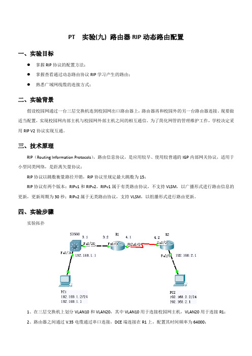
PT 实验(九) 路由器RIP动态路由配置一、实验目标●掌握RIP协议的配置方法;●掌握查看通过动态路由协议RIP学习产生的路由;●熟悉广域网线缆的连接方式;二、实验背景假设校园网通过一台三层交换机连到校园网出口路由器上,路由器再和校园外的另一台路由器连接。
现要做适当配置,实现校园网内部主机与校园网外部主机之间的相互通信。
为了简化网管的管理维护工作,学校决定采用RIP V2协议实现互通。
三、技术原理RIP(Routing Information Protocols),路由信息协议,是应用较早、使用较普通的IGP内部网关协议,适用于小型同类网络,是距离矢量协议;RIP协议以跳数衡量路径开销,RIP协议里规定最大跳数为15;RIP协议有两个版本:RIPv1和RIPv2,RIPv1属于有类路由协议,不支持VLSM,以广播形式进行路由信息的更新,更新周期为30秒;RIPv2属于无类路由协议,支持VLSM,以组播形式进行路由更新。
四、实验步骤实验拓扑1、在三层交换机上划分VLAN10和VLAN20,其中VLAN10用于连接校园网主机,VLAN20用于连接R1;2、路由器之间通过V.35电缆通过串口连接,DCE端连接在R1上,配置其时间频率为64000;3、主机和交换机通过直连线连接,主机与路由器通过交叉线连接;4、在S3560上配置RIPv2路由协议;5、在路由器R1、R2上配置RIPv2路由协议;6、将PC1、PC2主机默认网关分别设置为与直连网络设备接口IP地址;7、验证PC1、PC2主机之间可以互相通信;S3560:Switch>Switch>enSwitch#conf tEnter configuration commands, one per line. End with CNTL/Z.Switch(config)#hostname S3560S3560(config)#vlan 10S3560(config-vlan)#exitS3560(config)#vlan 20S3560(config-vlan)#exitS3560(config)#interface fa0/10S3560(config-if)#switchport access vlan 10S3560(config-if)#exitS3560(config)#interface fa0/20S3560(config-if)#switchport access vlan 20S3560(config-if)#exitS3560(config)#interface vlan 10%LINK-5-CHANGED: Interface Vlan10, changed state to up%LINEPROTO-5-UPDOWN: Line protocol on Interface Vlan10, changed state to up S3560(config-if)#ip address 192.168.1.1 255.255.255.0S3560(config-if)#exitS3560(config)#interface vlan 20%LINK-5-CHANGED: Interface Vlan20, changed state to upS3560(config-if)#ip address 192.168.3.1 255.255.255.0S3560(config-if)#exitS3560#%SYS-5-CONFIG_I: Configured from console by consoleS3560#show ip routeCodes: C - connected, S - static, I - IGRP, R - RIP, M - mobile, B - BGPD - EIGRP, EX - EIGRP external, O - OSPF, IA - OSPF inter areaN1 - OSPF NSSA external type 1, N2 - OSPF NSSA external type 2E1 - OSPF external type 1, E2 - OSPF external type 2, E - EGPi - IS-IS, L1 - IS-IS level-1, L2 - IS-IS level-2, ia - IS-IS inter area* - candidate default, U - per-user static route, o - ODRP - periodic downloaded static routeGateway of last resort is not setC 192.168.1.0/24 is directly connected, Vlan10S3560(config)#router rip //配置rip路由协议S3560(config-router)#network 192.168.1.0S3560(config-router)#network 192.168.3.0S3560(config-router)#version 2S3560(config-router)#endS3560#%LINK-5-CHANGED: Interface FastEthernet0/20, changed state to up%LINEPROTO-5-UPDOWN: Line protocol on Interface FastEthernet0/20, changed state to up %LINEPROTO-5-UPDOWN: Line protocol on Interface Vlan20, changed state to up //当配置好所有RIPv2后,再查看路由信息S3560#show ip routeCodes: C - connected, S - static, I - IGRP, R - RIP, M - mobile, B - BGPD - EIGRP, EX - EIGRP external, O - OSPF, IA - OSPF inter areaN1 - OSPF NSSA external type 1, N2 - OSPF NSSA external type 2E1 - OSPF external type 1, E2 - OSPF external type 2, E - EGPi - IS-IS, L1 - IS-IS level-1, L2 - IS-IS level-2, ia - IS-IS inter area* - candidate default, U - per-user static route, o - ODRP - periodic downloaded static routeGateway of last resort is not setC 192.168.1.0/24 is directly connected, Vlan10R 192.168.2.0/24 [120/2] via 192.168.3.2, 00:00:01, Vlan20C 192.168.3.0/24 is directly connected, Vlan20R 192.168.4.0/24 [120/1] via 192.168.3.2, 00:00:01, Vlan20S3560#R1:Router>enRouter#conf tEnter configuration commands, one per line. End with CNTL/Z.Router(config)#hostname R1R1(config)#interface fa0/0R1(config-if)#ip address 192.168.3.2 255.255.255.0R1(config-if)#no shutdown%LINK-5-CHANGED: Interface FastEthernet0/0, changed state to up%LINEPROTO-5-UPDOWN: Line protocol on Interface FastEthernet0/0, changed state to up R1(config-if)#exitR1(config)#interface serial 0/0R1(config-if)#ip address 192.168.4.1 255.255.255.0R1(config-if)#no shutdown%LINK-5-CHANGED: Interface Serial0/0, changed state to downR1(config-if)#clock rate 64000R1(config-if)#exitR1#show ip routeCodes: C - connected, S - static, I - IGRP, R - RIP, M - mobile, B - BGPD - EIGRP, EX - EIGRP external, O - OSPF, IA - OSPF inter areaN1 - OSPF NSSA external type 1, N2 - OSPF NSSA external type 2E1 - OSPF external type 1, E2 - OSPF external type 2, E - EGPi - IS-IS, L1 - IS-IS level-1, L2 - IS-IS level-2, ia - IS-IS inter area* - candidate default, U - per-user static route, o - ODRP - periodic downloaded static routeGateway of last resort is not setR 192.168.1.0/24 [120/1] via 192.168.3.1, 00:00:15, FastEthernet0/0C 192.168.3.0/24 is directly connected, FastEthernet0/0R1(config)#router rip //配置rip路由协议R1(config-router)#network 192.168.3.0R1(config-router)#network 192.168.4.0R1(config-router)#version 2R1(config-router)#end%SYS-5-CONFIG_I: Configured from console by console%LINK-5-CHANGED: Interface Serial0/0, changed state to up%LINEPROTO-5-UPDOWN: Line protocol on Interface Serial0/0, changed state to up //当配置好所有RIPv2后,再查看路由信息R1#show ip routeCodes: C - connected, S - static, I - IGRP, R - RIP, M - mobile, B - BGPD - EIGRP, EX - EIGRP external, O - OSPF, IA - OSPF inter areaN1 - OSPF NSSA external type 1, N2 - OSPF NSSA external type 2E1 - OSPF external type 1, E2 - OSPF external type 2, E - EGPi - IS-IS, L1 - IS-IS level-1, L2 - IS-IS level-2, ia - IS-IS inter area* - candidate default, U - per-user static route, o - ODRP - periodic downloaded static routeGateway of last resort is not setR 192.168.1.0/24 [120/1] via 192.168.3.1, 00:00:19, FastEthernet0/0R 192.168.2.0/24 [120/1] via 192.168.4.2, 00:00:11, Serial0/0C 192.168.3.0/24 is directly connected, FastEthernet0/0C 192.168.4.0/24 is directly connected, Serial0/0R1#R2:Router>enRouter#conf tEnter configuration commands, one per line. End with CNTL/Z.Router(config)#hostname R2R2(config)#interface fa0/0R2(config-if)#ip address 192.168.2.1 255.255.255.0R2(config-if)#no shutdown%LINK-5-CHANGED: Interface FastEthernet0/0, changed state to up%LINEPROTO-5-UPDOWN: Line protocol on Interface FastEthernet0/0, changed state to up R2(config-if)#exitR2(config)#interface Serial 0/0R2(config-if)#ip address 192.168.4.2 255.255.255.0R2(config-if)#no shutdown%LINK-5-CHANGED: Interface Serial0/0, changed state to up%LINEPROTO-5-UPDOWN: Line protocol on Interface Serial0/0, changed state to upR2(config-if)#exitR2(config)#end%SYS-5-CONFIG_I: Configured from console by consoleR2#show ip routeCodes: C - connected, S - static, I - IGRP, R - RIP, M - mobile, B - BGPD - EIGRP, EX - EIGRP external, O - OSPF, IA - OSPF inter areaN1 - OSPF NSSA external type 1, N2 - OSPF NSSA external type 2E1 - OSPF external type 1, E2 - OSPF external type 2, E - EGPi - IS-IS, L1 - IS-IS level-1, L2 - IS-IS level-2, ia - IS-IS inter area* - candidate default, U - per-user static route, o - ODRP - periodic downloaded static routeGateway of last resort is not setC 192.168.2.0/24 is directly connected, FastEthernet0/0C 192.168.4.0/24 is directly connected, Serial0/0R2#conf tEnter configuration commands, one per line. End with CNTL/Z.R2(config)#router ripR2(config-router)#network 192.168.2.0R2(config-router)#network 192.168.4.0R2(config-router)#version 2R2(config-router)#end%SYS-5-CONFIG_I: Configured from console by console//当配置好所有RIPv2后,再查看路由信息R2#show ip routeCodes: C - connected, S - static, I - IGRP, R - RIP, M - mobile, B - BGPD - EIGRP, EX - EIGRP external, O - OSPF, IA - OSPF inter areaN1 - OSPF NSSA external type 1, N2 - OSPF NSSA external type 2E1 - OSPF external type 1, E2 - OSPF external type 2, E - EGPi - IS-IS, L1 - IS-IS level-1, L2 - IS-IS level-2, ia - IS-IS inter area* - candidate default, U - per-user static route, o - ODRP - periodic downloaded static routeGateway of last resort is not setR 192.168.1.0/24 [120/2] via 192.168.4.1, 00:00:00, Serial0/0C 192.168.2.0/24 is directly connected, FastEthernet0/0R 192.168.3.0/24 [120/1] via 192.168.4.1, 00:00:00, Serial0/0C 192.168.4.0/24 is directly connected, Serial0/0R2#五、测试Packet Tracer PC Command Line 1.0PC>ipconfigIP Address......................: 192.168.2.2Subnet Mask.....................: 255.255.255.0Default Gateway.................: 192.168.2.1PC>ping 192.168.1.2Pinging 192.168.1.2 with 32 bytes of data:Request timed out.Request timed out.Reply from 192.168.1.2: bytes=32 time=16ms TTL=125Reply from 192.168.1.2: bytes=32 time=17ms TTL=125Ping statistics for 192.168.1.2:Packets: Sent = 4, Received = 2, Lost = 2 (50% loss), Approximate round trip times in milli-seconds:Minimum = 16ms, Maximum = 17ms, Average = 16ms PC>ping 192.168.1.2Pinging 192.168.1.2 with 32 bytes of data:Reply from 192.168.1.2: bytes=32 time=19ms TTL=125Reply from 192.168.1.2: bytes=32 time=16ms TTL=125Reply from 192.168.1.2: bytes=32 time=13ms TTL=125Reply from 192.168.1.2: bytes=32 time=15ms TTL=125Ping statistics for 192.168.1.2:Packets: Sent = 4, Received = 4, Lost = 0 (0% loss), Approximate round trip times in milli-seconds:Minimum = 13ms, Maximum = 19ms, Average = 15ms PC>。
动态路由的配置实验报告

动态路由的配置实验报告动态路由的配置实验报告引言:随着网络的快速发展,网络设备的数量和规模也在不断增加。
对于大型网络而言,静态路由已经无法满足其复杂的网络拓扑结构和高效的数据传输需求。
因此,动态路由的配置成为了网络管理中的重要环节。
本文将介绍动态路由的配置实验过程以及实验结果。
一、实验背景在网络中,路由器是实现数据包转发的重要设备。
静态路由是通过手动配置路由表来实现数据包的转发,而动态路由则是通过路由协议自动学习和更新路由表。
动态路由的配置可以大大减轻网络管理员的工作量,提高网络的可扩展性和灵活性。
二、实验目的本次实验的目的是通过配置动态路由协议,实现网络设备之间的自动学习和更新路由表,从而实现数据包的快速转发和高效传输。
三、实验环境本次实验使用了GNS3网络模拟器搭建实验环境。
实验中使用的设备包括路由器R1、R2和R3,它们之间通过以太网连接。
实验中采用的动态路由协议是开放最短路径优先(OSPF)协议。
四、实验步骤1. 配置设备IP地址:首先,为每个设备配置IP地址,确保它们可以相互通信。
2. 配置OSPF协议:在每个路由器上启动OSPF进程,并配置相应的区域。
3. 配置网络接口:将每个设备的接口与OSPF进程绑定,并设置相应的开销值。
4. 验证路由信息:通过查看路由表和邻居关系表,验证OSPF协议是否正常工作。
五、实验结果经过以上步骤的配置,我们成功实现了动态路由的配置。
通过查看路由表,可以看到每个路由器已经学习到了相应的网络信息,并且能够选择最短路径进行数据包的转发。
同时,通过查看邻居关系表,可以确认路由器之间已经建立了相互的邻居关系。
六、实验总结通过本次实验,我们深入了解了动态路由的配置过程,并成功实现了网络设备之间的自动学习和更新路由表。
动态路由的配置可以大大简化网络管理的工作,提高网络的可扩展性和灵活性。
同时,我们也了解到动态路由协议的选择和配置对网络性能和稳定性有着重要影响,需要根据实际需求进行合理选择和配置。
- 1、下载文档前请自行甄别文档内容的完整性,平台不提供额外的编辑、内容补充、找答案等附加服务。
- 2、"仅部分预览"的文档,不可在线预览部分如存在完整性等问题,可反馈申请退款(可完整预览的文档不适用该条件!)。
- 3、如文档侵犯您的权益,请联系客服反馈,我们会尽快为您处理(人工客服工作时间:9:00-18:30)。
r1的配置:Press Enter to StartRouter>Router>enRouter#config tEnter configuration commands, one per line. End with CNTL/Z. Router(config)#hostname router1router1(config)#interface e0router1(config-if)#ip address 192.168.1.1 255.255.255.0router1(config-if)#no shut%LINK-3-UPDOWN: Interface Ethernet0, changed state to uprouter1(config-if)#interface s0router1(config-if)#ip address 192.168.2.1 255.255.255.0router1(config-if)#clock rate 64000router1(config-if)#no shut%LINK-3-UPDOWN: Interface Serial0, changed state to uprouter1(config-if)#exit%LINK-3-UPDOWN: Interface Serial0, changed state to down%LINEPROTO-5-UPDOWN: Line protocol on Interface Serial0, changed state to downrouter1(config)#router rip //启用rip协议router1(config-router)#network 192.168.1.0 //需要给出与本路由器直连的网络router1(config-router)#network 192.168.2.0 //此处分别为192.168.1. 0和192.168.2.0router1(config-router)#exitrouter1(config)#exitrouter1#copy running startup-config //在路由器上保存路由信息Destination filename [startup-config]?Building configuration...[OK]%LINK-3-UPDOWN: Interface Serial0, changed state to up%LINEPROTO-5-UPDOWN: Line protocol on Interface Serial0, changed state to upr2的配置:Press Enter to StartRouter>enRouter#con terminalEnter configuration commands, one per line. End with CNTL/Z.Router(config)#hostname router2router2(config)#interface s0router2(config-if)#ip address 192.168.2.2 255.255.255.0router2(config-if)#no shut%LINK-3-UPDOWN: Interface Serial0, changed state to uprouter2(config-if)#interface e0router2(config-if)#ip address 192.168.3.1 255.255.255.0router2(config-if)#no shut%LINK-3-UPDOWN: Interface Ethernet0, changed state to uprouter2(config-if)#exitrouter2(config)#router riprouter2(config-router)#network 192.168.3.0router2(config-router)#network 192.168.2.0router2(config-router)#exitrouter2(config)#exitrouter2#copy running-config startup-configDestination filename [startup-config]?Building configuration...[OK]router2#ping 192.168.2.1 //试ping一下,完全正确Type escape sequence to abort.Sending 5, 100-byte ICMP Echos to 192.168.2.1, timeout is 2 seconds:!!!!!Success rate is 100 percent (5/5), round-trip min/avg/max = 1/2/4 msrouter2#ping 192.168.2.2Type escape sequence to abort.Sending 5, 100-byte ICMP Echos to 192.168.2.2, timeout is 2 seconds: !!!!!Success rate is 100 percent (5/5), round-trip min/avg/max = 1/2/4 mspc1的配置:Boson BOSS 5.0Copyright 1998-2003 Boson Software, Inc.Use the command help to get startedPress Enter to beginC:>ipconfig /ip 192.168.1.2 255.255.255.0C:>ipconfig /dg 192.168.1.1C:>ping 192.168.3.2Pinging 192.168.3.2 with 32 bytes of data: //正式开始测试,完全正确Reply from 192.168.3.2: bytes=32 time=60ms TTL=241Reply from 192.168.3.2: bytes=32 time=60ms TTL=241Reply from 192.168.3.2: bytes=32 time=60ms TTL=241Reply from 192.168.3.2: bytes=32 time=60ms TTL=241Reply from 192.168.3.2: bytes=32 time=60ms TTL=241Ping statistics for 192.168.3.2: Packets: Sent = 5, Received = 5, Los t = 0 (0% loss),Approximate round trip times in milli-seconds:Minimum = 50ms, Maximum = 60ms, Average = 55msC:>ping 192.168.3.1Pinging 192.168.3.1 with 32 bytes of data:Reply from 192.168.3.1: bytes=32 time=60ms TTL=241Reply from 192.168.3.1: bytes=32 time=60ms TTL=241Reply from 192.168.3.1: bytes=32 time=60ms TTL=241Reply from 192.168.3.1: bytes=32 time=60ms TTL=241Reply from 192.168.3.1: bytes=32 time=60ms TTL=241Ping statistics for 192.168.3.1: Packets: Sent = 5, Received = 5, Los t = 0 (0% loss),Approximate round trip times in milli-seconds:Minimum = 50ms, Maximum = 60ms, Average = 55msC:>ping 192.168.2.2Pinging 192.168.2.2 with 32 bytes of data:Reply from 192.168.2.2: bytes=32 time=60ms TTL=241Reply from 192.168.2.2: bytes=32 time=60ms TTL=241Reply from 192.168.2.2: bytes=32 time=60ms TTL=241Reply from 192.168.2.2: bytes=32 time=60ms TTL=241Reply from 192.168.2.2: bytes=32 time=60ms TTL=241Ping statistics for 192.168.2.2: Packets: Sent = 5, Received = 5, Los t = 0 (0% loss),Approximate round trip times in milli-seconds:Minimum = 50ms, Maximum = 60ms, Average = 55msC:>ping 192.168.2.1Pinging 192.168.2.1 with 32 bytes of data:Reply from 192.168.2.1: bytes=32 time=60ms TTL=241Reply from 192.168.2.1: bytes=32 time=60ms TTL=241Reply from 192.168.2.1: bytes=32 time=60ms TTL=241Reply from 192.168.2.1: bytes=32 time=60ms TTL=241Reply from 192.168.2.1: bytes=32 time=60ms TTL=241Ping statistics for 192.168.2.1: Packets: Sent = 5, Received = 5, Los t = 0 (0% loss),Approximate round trip times in milli-seconds:Minimum = 50ms, Maximum = 60ms, Average = 55msC:>ping 192.168.1.2Pinging 192.168.1.2 with 32 bytes of data:Reply from 192.168.1.2: bytes=32 time=60ms TTL=241Reply from 192.168.1.2: bytes=32 time=60ms TTL=241Reply from 192.168.1.2: bytes=32 time=60ms TTL=241Reply from 192.168.1.2: bytes=32 time=60ms TTL=241Reply from 192.168.1.2: bytes=32 time=60ms TTL=241Ping statistics for 192.168.1.2: Packets: Sent = 5, Received = 5, Los t = 0 (0% loss),Approximate round trip times in milli-seconds:Minimum = 50ms, Maximum = 60ms, Average = 55mspc2 的配置:Boson BOSS 5.0Copyright 1998-2003 Boson Software, Inc.Use the command help to get startedPress Enter to beginC:>ipconfig /ip 192.168.3.2 255.255.255.0C:>ipconfig /dg 192.168.3.1C:>ping 192.168.1.1Pinging 192.168.1.1 with 32 bytes of data: //正式测试,完全正确Reply from 192.168.1.1: bytes=32 time=60ms TTL=241Reply from 192.168.1.1: bytes=32 time=60ms TTL=241Reply from 192.168.1.1: bytes=32 time=60ms TTL=241Reply from 192.168.1.1: bytes=32 time=60ms TTL=241Reply from 192.168.1.1: bytes=32 time=60ms TTL=241t = 0 (0% loss),Approximate round trip times in milli-seconds:Minimum = 50ms, Maximum = 60ms, Average = 55msC:>ping 192.168.1.2Pinging 192.168.1.2 with 32 bytes of data:Reply from 192.168.1.2: bytes=32 time=60ms TTL=241Reply from 192.168.1.2: bytes=32 time=60ms TTL=241Reply from 192.168.1.2: bytes=32 time=60ms TTL=241Reply from 192.168.1.2: bytes=32 time=60ms TTL=241Reply from 192.168.1.2: bytes=32 time=60ms TTL=241Ping statistics for 192.168.1.2: Packets: Sent = 5, Received = 5, Los t = 0 (0% loss),Approximate round trip times in milli-seconds:Minimum = 50ms, Maximum = 60ms, Average = 55msC:>ping 192.168.2.1Pinging 192.168.2.1 with 32 bytes of data:Reply from 192.168.2.1: bytes=32 time=60ms TTL=241Reply from 192.168.2.1: bytes=32 time=60ms TTL=241Reply from 192.168.2.1: bytes=32 time=60ms TTL=241Reply from 192.168.2.1: bytes=32 time=60ms TTL=241Reply from 192.168.2.1: bytes=32 time=60ms TTL=241Ping statistics for 192.168.2.1: Packets: Sent = 5, Received = 5, Los t = 0 (0% loss),Approximate round trip times in milli-seconds:Minimum = 50ms, Maximum = 60ms, Average = 55msC:>ping 192.168.2.2Pinging 192.168.2.2 with 32 bytes of data:Reply from 192.168.2.2: bytes=32 time=60ms TTL=241Reply from 192.168.2.2: bytes=32 time=60ms TTL=241Reply from 192.168.2.2: bytes=32 time=60ms TTL=241Reply from 192.168.2.2: bytes=32 time=60ms TTL=241Reply from 192.168.2.2: bytes=32 time=60ms TTL=241Ping statistics for 192.168.2.2: Packets: Sent = 5, Received = 5, Los t = 0 (0% loss),Approximate round trip times in milli-seconds:Minimum = 50ms, Maximum = 60ms, Average = 55msC:>ping 192.168.3.1Pinging 192.168.3.1 with 32 bytes of data:Reply from 192.168.3.1: bytes=32 time=60ms TTL=241Reply from 192.168.3.1: bytes=32 time=60ms TTL=241Reply from 192.168.3.1: bytes=32 time=60ms TTL=241Reply from 192.168.3.1: bytes=32 time=60ms TTL=241Reply from 192.168.3.1: bytes=32 time=60ms TTL=241t = 0 (0% loss),Approximate round trip times in milli-seconds:Minimum = 50ms, Maximum = 60ms, Average = 55msC:>ping 192.168.3.2Pinging 192.168.3.2 with 32 bytes of data:Reply from 192.168.3.2: bytes=32 time=60ms TTL=241Reply from 192.168.3.2: bytes=32 time=60ms TTL=241Reply from 192.168.3.2: bytes=32 time=60ms TTL=241Reply from 192.168.3.2: bytes=32 time=60ms TTL=241Reply from 192.168.3.2: bytes=32 time=60ms TTL=241Ping statistics for 192.168.3.2: Packets: Sent = 5, Received = 5, Los t = 0 (0% loss),Approximate round trip times in milli-seconds:Minimum = 50ms, Maximum = 60ms, Average = 55msC:>下面是show run查看的r1的部分配置情况:interface Serial0ip address 192.168.2.1 255.255.255.0no ip directed-broadcast!interface Ethernet0ip address 192.168.1.2 255.255.255.0no ip directed-broadcast!!router ripnetwork 192.168.1.0network 192.168.2.0!ip classlessno ip http server!!!line con 0transport input noneline aux 0line vty 0 4!no scheduler allocateendshow run查看的r2的部分配置情况:interface Serial0ip address 192.168.2.2 255.255.255.0 no ip directed-broadcast!interface Ethernet0ip address 192.168.3.1 255.255.255.0 no ip directed-broadcast!!router ripnetwork 192.168.3.0network 192.168.2.0!ip classlessno ip http server!!!line con 0transport input noneline aux 0line vty 0 4!no scheduler allocateend。