MOXA串口服务器产品配置说明书
MOXA串口服务器NPORT_5130详细配置
MOXA串口服务器NPORT_5130详细配置MOXANPORT_5130是一款高性能的串口服务器,它可以将串口设备连接到以太网网络,从而实现远程管理和控制。
下面详细介绍了NPORT_5130的配置步骤和功能。
1.连接硬件:a.将NPORT_5130的以太网口连接到网络交换机或路由器的可用端口。
b.将串口设备连接到NPORT_5130的串口端口。
2.配置IP地址:a.使用网线将计算机连接到NPORT_5130的以太网口。
b. 打开一个Web浏览器,输入默认IP地址192.168.127.254并按Enter键。
c. 在弹出的登录页面中,输入默认用户名和密码(admin/admin),然后点击登录。
d. 进入配置界面后,选择Network Settings(网络设置),然后配置与您的网络环境相匹配的IP地址、子网掩码和网关。
3.配置串口参数:a. 在配置界面中,选择Serial Settings(串口设置)。
b.首先配置串口数量和串口类型(RS-232或RS-485)。
c.然后,为每个串口设置基本参数,如波特率、数据位、校验位和停止位。
d.您还可以设置串口流控制选项,如硬件流控制和软件流控制。
4.高级功能配置:a. 在配置界面中,选择Advanced Settings(高级设置)。
b.在这里,您可以配置各种高级功能,如状态报告、自动控制、特定字符过滤和串口映射。
c.状态报告功能允许您定期获取串口设备的状态信息。
d.自动控制功能允许您定义一些预设规则,以便在特定条件下自动执行一些动作。
e.特定字符过滤功能允许您设置特定的字符或字符序列,以便在串口数据中过滤或替换它们。
f.串口映射功能允许您将多个串口设备映射到一个虚拟串口,简化了串口设备的管理。
5.安全性配置:a. 在配置界面中,选择Security Settings(安全设置)。
b.在这里,您可以配置各种安全功能,如用户管理和访问控制列表。
c.用户管理功能允许您创建多个用户帐户,并为每个帐户指定不同的访问权限。
MOXA串口服务器中文使用文档

MOXA串口服务器中文使用文档一、引言二、安装1.要开始使用MOXA串口服务器,首先需要将设备连接到计算机上。
将设备的以太网端口连接到计算机上的以太网接口,并将串行设备连接到设备的串口接口。
2.将设备的电源适配器插入电源插座,并将适配器的连接线插入设备的电源接口。
3.打开计算机上的浏览器,输入设备的IP地址,在浏览器中打开设备的管理界面。
三、配置1.在设备的管理界面中,点击"配置"选项卡,进入设备的配置界面。
2.在配置界面中,可以配置设备的网络设置、串口配置和其他高级设置。
3.首先要配置设备的网络设置,包括IP地址、子网掩码、网关等信息。
确保设备的网络设置与计算机的网络设置相匹配,以便能够正确地连接到网络。
4.然后要配置设备的串口设置,包括波特率、数据位、停止位、校验位等信息。
根据需要配置串口的参数,以确保与串行设备的通信正常。
5.在完成网络和串口配置后,可以进行其他高级设置,如用户管理、安全设置、升级固件等。
根据需要进行相应的配置。
四、使用1.配置完成后,可以通过网络连接到MOXA串口服务器,并与串行设备进行通信。
2.打开计算机上的终端模拟程序,使用串口连接到设备的IP地址和端口号。
3.在终端模拟程序中,可以通过串口与串行设备进行交互。
发送命令或数据到串行设备,并接收串行设备返回的响应。
4.可以使用终端模拟程序提供的功能来控制串行设备,如发送命令、接收数据、保存日志等。
五、注意事项1.在使用MOXA串口服务器时,要确保设备的网络设置和串口设置正确无误,以确保与串行设备的通信正常。
2.在与串行设备进行通信时,要注意设备的串口配置与串行设备的要求相匹配,以确保数据的正确传输。
3.在进行高级设置时,要谨慎操作,避免对设备的正常运行产生不良影响。
六、总结本文档介绍了MOXA串口服务器的安装、配置和使用方法。
通过按照文档中的步骤进行操作,用户可以成功地将串行设备连接到网络,并实现与串行设备的通信。
MOXA串口服务器NPORT_5130详细配置

MOXA串口联网服务器 NPORT 5130特点- 以太网口支持100/10M自适应,串口支持RS-422,RS-485(2w/4w)- 低成本、信用卡大小- 支持Windows/Linux COM串口驱动程序模式- 提供包括TCP Server、TCP Client、UDP Server/Client和 Ethernet Modem 在内的不同socket操作模式- 无需PC、可通过网络连接两个串口设备的对等连接模式- 易于使用、可用于批量安装的Windows工具- 所有信号内置15 KV突波保护- 支持网络管理协议SNMP MIB-II- 可通过网络Web/Telnet进行配置MOXA针对串口联网服务器开发了软件NPort Administrator,方便用户配置,下面我就着重讲如何用Nport Administration 配置NPORT产品,图一1、NPORT 5130提供多种操作模式,例如:Real com模式,Tcp server模式,Tcp client模式,Udp模式。
图二2、配置方法:2.1、安装NPORT administration 软件。
2.2、打开软件,如图:图三点击Search,可以搜索到局域网中所有的NPORT设备,包括和主机IP不同网段的NPORT设备。
搜索到设备如下图:图四如图可以显示设备的型号,MAC地址,IP地址,以及设备的名称。
(默认IP:192.168.127.254)2.3、基本设置界面介绍选中要配置的设备,点击右键——Configuer,或者是双击,进入设备配置界面,如图:图五如图五,Basic界面可以设置设备的名称,设备的时钟(默认读取主机时钟),以及登陆设备的方式。
(提醒:必须勾选Modofy才能对配置进行修改,否则只能对查看配置)2.4、网络设置页面介绍图六如图六,Network界面配置Ip地址相关信息。
设置串口联网服务器IP地址与主机IP 为同一个网段。
莫卡(Moxa)产品说明书

Copyright © 2017 Moxa Inc. Released on December 28, 2017About MoxaMoxa is a leading manufacturer of industrial networking, computing, and automationsolutions. With over 25 years of industry experience, Moxa has connected more than 30 million devices worldwide and has a distribution and service network that reachescustomers in more than 70 countries. Moxa delivers lasting business value by empowering industry with reliable networks and sincere service for automation systems. Information about Moxa’s solutions is available at . You may also contact Moxa by email at *************. How to Contact Moxa Tel: +886-2-8919-1230 How to Use the TIA Portal to Set a Siemens PLC and the MGate 5111Moxa Technical Support Team****************Contents1 Application Description ...................................................................2 2 System Topology .............................................................................3 3Required Equipment and Components (4)A. TIA Portal .................................................................................................... 4B. Modbus Slave .............................................................................................. 4C.MGate 5111 Firmware (4)D. MGate 5111’s GSD File (4)4MGate 5111 Setting (5)A. Protocol Conversion ...................................................................................... 5B. Configure Modbus Commands ........................................................................ 5C.Configure PROFIBUS Module (7)D. I/O Data Mapping (8)5 Siemens PLC Setting ....................................................................... 9 6Communication Test (21)A. Status Monitoring ........................................................................................21 B. Fault Protection . (27)1Application DescriptionThe TIA Portal is Siemens’s new software platform to configure and programS7-300/400/1200/1500 PLCs. This technical note demonstrates how to configure theSiemens S7-300 to connect with the MGate 5111 in TIA Portal V14.The MGate 5111 supports a variety of maintenance functions, such as Protocol Diagnostics, Traffic Monitoring, Status Monitoring, and Fault Protection. The Status Monitoringfunction notifies a PLC/DCS/SCADA system when a Modbus device gets disconnected or does not respond. If a command has run successfully, the status bit’s value will be 1. If a command has failed, the status bit’s value will be 0. In this case, the master device will be aware of the failure status of the slave device. When a PROFIBUS cable gets disconnected, the Fault Protection function executes actions on end devices identified by a pre-defined value set by the user.This technical note demonstrates how PROFIBUS Master (Siemens PLC) get these Modbus command statuses by receiving Input Status module values, as well as how the FaultProtection function works. We also demonstrate how Protocol Diagnostics and TrafficMonitoring make troubleshooting easy.2System TopologyThis technical note demonstrates how to exchange data between a PROFIBUS master and six Modbus TCP slaves. The Modbus TCP slave IDs 1-3 use Modbus Read command and show the Status Monitoring function. The Modbus TCP slave IDs 4-6 use Modbus Write command and show the Fault Protection function.We use the Siemens S7-300 as the PROFIBUS Master to connect the MGate 5111’s PROFIBUS port. On a PC, we run a Modbus Slave tool to simulate Modbus TCP slaves that the MGate 5111 will connect to the PC’s TCP 502 to poll slaves.3Required Equipment and ComponentsA.TIA PortalAs a registered Siemens’s customer you can download the trial software for TIA PortalV14 and test it for 21 days.Version: V14Download Website:https:///cs/document/109740158/simatic-step-7-(tia-portal)-v14-trial-download?dti=0&lc=en-WWB.Modbus SlaveModbus Slave is a popular Modbus slave simulator to test and debug your modbusdevices. Supports Modbus RTU/ASCII and Modbus TCP/IP.Version: V6+Download Website:/download.htmlC.MGate 5111 FirmwareVersion: V.1.0Download Website: D.MGate 5111’s GSD FileThe GSD (General Station Description) file is an electronic device datasheet or device database file that identifies the PROFIBUS IO device. This file can be installed into a PROFIBUSEngineering tool, e.g., TIA Portal so that the PROFIBUS Engineering tool can configure thisPROFIBUS IO Device.Version: V.1.0 or higherDownload Website: Note: For wiring, please refer to the MGate 5111 User’s Manual4 MGate 5111 SettingFor details, please refer to the MGate 5111 user’s manual that you can download from A. Protocol ConversionLogin to the MGate 5111’s Web Console. Set Protocol Conversion : Role 1 as PROFIBUS Slave and Role 2 as TCP Client.B. Configure Modbus CommandsUnder Modbus TCP settings , set Max. retry as 0. The default value is 3. Changing this value to 0 is in order to quickly demonstrate the detection that the TCP command has failed.Then add below Function Code 03 commands to poll Slave ID1- ID3’s register 0, and add Function Code 06 commands to write Slave ID4-ID6’s register 0.Keep ID4’s Fault Protection command as Keep latest data.For ID5 Fault Protection command, choose Clear all data bit to 0 and set Fault timeout as 10000 ms.For ID6 Fault Protection command, choose Set to user defined value and set Fault value as 0xFF 0xFF. Fault timeout is set as 10000 ms.C.Configure PROFIBUS ModuleAdd Input Module 1 words to Slot 1-3 to map the register values of Modbus Slave ID 1-3.Add Input Status Module to store the Modbus TCP command status on Slot 4. AddOutput: 1 word modules to slots 5-7 to write the value on the registers of Modbus Slave IDs 4~6.D. I/O Data MappingLet the MGate auto map the data on both sides of the MGate’s IO Internal Memory. Modbus read commands fit PROFIBUS Module 1-3 as below. Take note that the input status module is not included in MGate’s IO Internal Memory.On the other data flow, we can see PROFIBUS Modules 5-7 fit ID4 and ID5’s Modbus write commands as follows:5Siemens PLC Setting(1)Create a new project.(2)Once the new project has been created successfully, click Configure a device toadd the PLC.To add the actual PLC’s CPU model, select it from Controllers CPU as below:(3) Click PLC’s PROFINET interface to set its IP Address .(4)Click PLC’s MPI/DP interface to set Interface Type as PROFIBUS.Click Add new subne t to add a PROFIBUS subnet.Then a PROFIBUS_1 subnet is created. You can modify the PROFIBUS baudrate by modifying Transmission Speed5111’s GSD file.Select the MGate 5111’s GSD file then click Install .Make sure the installation is a success.(6)In the Hardware catalog window, we can filter “moxa” to search the MGate 5111. Choose the MGate 5111 device icon, then drag and drop to PROFIBUS_1 subnet.(7) Click Not assigned to assign the MGate 5111 to PLC_1.Then the MGate 5111 is set into PLC_1’s DP Master System.(8) In the MGate 5111’s Device view , drag and drop Input 1 Word to Slot 1-3 and Input 1 Byte to Slot 4. Assign their I address to 0-6.Drag and drop Output 1 Word to Slot 5-7. Assign their Q address to 0-5.(9) Under the MGate 5111’s Properties , set its PROFIBUS address as its actual address, which is set by hardware’s rotary switch.(10)We want to get Modbus ID1-ID3’s register value and make sure the Modbuscommands’ responses are valid. If a Modbus command’s response is invalid or times out, the register value will show a specific value. In this demonstration, we will use a program to set this value as 0xFFFF. We will show details later.We created the following tags:Each Network program shows as follows:(11)Execute Compile and make sure there are no errors.(12)Execute DownloadClick Start Search to search for an accessible PLC.After locating an accessible PLC, execute Load .The TIA Portal will check hardware and software consistency. After checking for errors, click Load to download.After loading, enable Start all to start modules and then click Finish.6Communication TestA.Status Monitoring(1)The PC runs a Modbus Slave tool and listens on TCP port 502. Add slave IDs 1-3and set their register 0’s value as 1, 2, 3, respectively.(2)Click Add new watch table to create the Watch table_1.Add the following tags to be monitored:(3)Click Go online and then click Monitor all.When Input Status module shows a value of 7, then commands 1-3 are successful.ID1Value- ID3Value are running as 1, 2, 3, respectively.(4) We can use the MGate’s Protocol Diagnostics tool on the Web Console to checkModbus and PROFIBUS communication status:Via System Monitoring → Protocol Status → Modbus TCP Diagnose , we can see its connection status is OK with no invalid responses.Via System Monitoring → Protocol Status → Modbus TCP Traffic , we can log Modbus TCP communication traffic:Via System Monitoring → Protocol Status → PROFIBUS Slave Diagnose , we can see State’s value is note as Data Exchange :Via System Monitoring → Protocol Status → I/O Data View , we can choose PROFIBUS Master ← Modbus TCP Server data flow side to see Modbus slave input data:(5)Disable Modbus Slave ID 2 on the Modbus Slave tool, so Modbus Command 2can’t receive any responses. Check Watch table; Input Status module showsa value of 5 and ID2Value a value of 0xFFFF.Disable Modbus Slave ID 1 and 3 on the Modbus Slave tool. Check Modbus TCP Diagnose;Status shows that the Request_timeout and Timeout counters are increasing:B. Fault Protection(1)Add slave ID4-ID6 on the Modbus Slave tool as below:(2) On the Watch table, set Modify value on QW0 as 0x0004, QW2 as 0x0005, QW4 as 0x0006. Then click the Modify button.(3) Check Modbus Slave IDs 4-6; they are updated as 0x0004, 0x0005, 0x0006, respectively.Via System Monitoring → Protocol Status → I/O Data View, we can choosePROFIUS Master → Modbus/TCP Server data flow side to see the PROFIBUS output data:(4)Remove the PROFIBUS cable. After 10000 ms, the Fault Timeout is on. Checkwhether Modbus Slave ID 4’s register 0 value is still 0x0004. Slave ID 5’s register0 value is updated to 0x0000 and Slave ID 6’s register 0 to 0xFFFF.Check PROFIBUS Master Modbus/TCP Server data flow side. We can see they all updated as its Fault Value:Check PROFIBUS Slave. Its Baudrate shows Not Found and State shows Wait Parameterization:。
Moxa NPort 5100A 1-Port 串口设备服务器说明书

NPort5100A Series1-port RS-232/422/485serial device servers with serial surge protectionFeatures and Benefits•Power consumption of only1W•Fast3-step web-based configuration•Surge protection for serial,Ethernet,and power•COM port grouping and UDP multicast applications•Screw-type power connectors for secure installation•Real COM and TTY drivers for Windows,Linux,and macOS•Standard TCP/IP interface and versatile TCP and UDP operation modes•Connects up to8TCP hostsCertificationsIntroductionThe NPort®5100A device servers are designed to make serial devices network-ready in an instant and give your PC software direct access to serial devices from anywhere on the network.The NPort®5100A device servers are ultra-lean,ruggedized,and user-friendly,making simple and reliable serial-to-Ethernet solutions possible.A Greener Serial-to-Ethernet SolutionThe MiiNe is a small but powerful Arm-based serial-to-Ethernet SoC with RAM and Flash embedded.With the MiiNe inside,the NPort®5110A Series'power consumption is less than1W.The NPort®5100A Series saves at least50%on power consumption compared to existing solutions on the market,helping engineers meet the tough environmental compliance challenges found in today’s industrial environments.Surge Protection for Serial,Ethernet,and PowerSurge,which is typically caused by high voltages that result from switching and lightning transients,is a common threat to all electrical devices. Moxa’s leading-edge surge immunity solution,which is applied to the NPort®5100A’s serial,power,and Ethernet lines,is tested and proven compliant with IEC61000-4-5.This state-of-the-art surge protection provides a robust serial-to-Ethernet solution that can protect electrical devices from voltage spikes and withstand electrically noisy environmental conditions.3-Step Web-based ConfigurationThe NPort®5100A’s3-step web-based configuration tool is straightforward and user-friendly.The NPort®5100A’s web console guides users through three simple configuration steps that are necessary to activate the serial-to-Ethernet application.With this fast3-step web-based configuration,a user only needs to spend an average of30seconds to complete the NPort®settings and enable the application,saving a great amount of time and effort.Easy to TroubleshootNPort®5100A device servers support SNMP,which can be used to monitor all units over Ethernet.Each unit can be configured to send trap messages automatically to the SNMP manager when user-defined errors are encountered.For users who do not use SNMP manager,an email alert can be sent ers can define the trigger for the alerts using Moxa’s Windows utility,or the web console.For example,alerts can be triggered by a warm start,a cold start,or a password change.AppearanceSpecificationsEthernet Interface10/100BaseT(X)Ports(RJ45connector)1Magnetic Isolation Protection 1.5kV(built-in)Ethernet Software FeaturesConfiguration Options Windows Utility,Web Console(HTTP/HTTPS),Device Search Utility(DSU),MCC Tool,Telnet Console,Serial Console(NPort5110A/5150A models only)Management DHCP Client,ARP,BOOTP,DNS,HTTP,HTTPS,ICMP,IPv4,LLDP,SNTP,SMTP,SNMPv1/v2c,TCP/IP,Telnet,UDPFilter IGMP v1/v2Windows Real COM Drivers Windows95/98/ME/NT/2000,Windows XP/2003/Vista/2008/7/8/8.1/10/11(x86/x64),Windows2008R2/2012/2012R2/2016/2019(x64),Windows Server2022,WindowsEmbedded CE5.0/6.0,Windows XP EmbeddedLinux Real TTY Drivers Kernel versions:2.4.x,2.6.x,3.x,4.x,and5.xFixed TTY Drivers macOS10.12,macOS10.13,macOS10.14,macOS10.15,SCO UNIX,SCO OpenServer,UnixWare7,QNX4.25,QNX6,Solaris10,FreeBSD,AIX5.x,HP-UX11i,Mac OS X Android API Android3.1.x and laterMIB RFC1213,RFC1317Security FunctionsAuthentication Local databaseEncryption HTTPS,AES-128,SHA-1,RSA-1024,SHA-256Security Protocols HTTPS(TLS1.2)Serial InterfaceConnector DB9maleNo.of Ports1Serial Standards NPort5110A:RS-232NPort5130A:RS-422,RS-485NPort5150A:RS-232,RS-422,RS-485Operation Modes Disabled,Ethernet Modem,Pair Connection,Real COM,Reverse Telnet,RFC2217,TCPClient,TCP Server,UDPBaudrate Supports standard baudrates(unit=bps):50,75,110,134,150,300,600,1200,1800,2400,4800,7200,9600,19200,38400,57600,115200,230.4k,460.8k,921.6kData Bits5,6,7,8Stop Bits1,1.5,2Parity None,Even,Odd,Space,MarkFlow Control RTS/CTS(RS-232only),DTR/DSR(RS-232only),XON/XOFFPull High/Low Resistor for RS-4851kilo-ohm,150kilo-ohmsRS-485Data Direction Control NPort5150A/5150A-T/5130A/5130A-T:ADDC(automatic data direction control) Terminator for RS-485120ohmsSerial SignalsRS-232TxD,RxD,RTS,CTS,DTR,DSR,DCD,GNDRS-422Tx+,Tx-,Rx+,Rx-,GNDRS-485-4w Tx+,Tx-,Rx+,Rx-,GNDRS-485-2w Data+,Data-,GNDPower ParametersNo.of Power Inputs1Input Current NPort5110A:82.5mA@12VDCNPort5130A:89.1mA@12VDCNPort5150A:92.4mA@12VDCInput Voltage12to48VDCSource of Input Power Power input jackReliabilityAutomatic Reboot Trigger Built-in WDTPhysical CharacteristicsHousing MetalDimensions(with ears)75.2x80x22mm(2.96x3.15x0.87in)Dimensions(without ears)52x80x22mm(2.05x3.15x0.87in)Weight340g(0.75lb)Installation Desktop,DIN-rail mounting(with optional kit),Wall mountingEnvironmental LimitsOperating Temperature Standard Models:0to60°C(32to140°F)Wide Temp.Models:-40to75°C(-40to167°F)Storage Temperature(package included)-40to75°C(-40to167°F)Ambient Relative Humidity5to95%(non-condensing)Standards and CertificationsEMC EN55032/35EMI CISPR32,FCC Part15B Class AEMS IEC61000-4-2ESD:Contact:6kV;Air:8kVIEC61000-4-3RS:80MHz to1GHz:10V/mIEC61000-4-4EFT:Power:2kV;Signal:1kVIEC61000-4-5Surge:Power:2kV;Signal:0.5kVIEC61000-4-6CS:150kHz to80MHz:10V/m;Signal:10V/mIEC61000-4-8PFMFIEC61000-4-11Safety UL60950-1DeclarationGreen Product RoHS,CRoHS,WEEEMTBFTime2,231,530hrsStandards Telcordia(Bellcore)Standard TR/SRWarrantyWarranty Period5yearsDetails See /warrantyPackage ContentsDevice1x NPort5100A Series device serverPower Supply1x power adapter,suitable for your region(standard temp.models only) Documentation1x quick installation guide1x warranty cardDimensionsNPort5110A NPort5150ANPort5130AOrdering InformationModel NameOperating Temp.Baudrate Serial Standards No.of Serial Ports Input Current Input Voltage NPort 5110A 0to 60°C 50bps to 921.6kbpsRS-232182.5mA @12VDC 12-48VDC NPort 5110A-T -40to 75°C 50bps to 921.6kbpsRS-232182.5mA @12VDC 12-48VDC NPort 5130A 0to 60°C 50bps to 921.6kbps RS-422/485189.1mA @12VDC 12-48VDCNPort5130A-T-40to75°C 50bps to921.6kbpsRS-422/485189.1mA@12VDC12-48VDCNPort5150A0to60°C 50bps to921.6kbpsRS-232/422/485192.4mA@12VDC12-48VDCNPort5150A-T-40to75°C 50bps to921.6kbpsRS-232/422/485192.4mA@12VDC12-48VDCAccessories(sold separately)CablesCBL-F9M9-20DB9female to DB9male serial cable,20cmCBL-F9M9-150DB9female to DB9male serial cable,1.5mConnectorsADP-RJ458P-DB9F DB9female to RJ45connectorMini DB9F-to-TB DB9female to terminal block connectorDIN-Rail Mounting KitsDK35A DIN-rail mounting kit,35mmPower AdaptersPWR-12050-WPAU-S1Locking barrel plug,12VDC,0.5A,100to240VAC,Australia(AU)plug,0to40°C operatingtemperaturePWR-12050-WPCN-S1Locking barrel plug,12VDC,0.5A,100to240VAC,China(CN)plug,0to40°C operating temperature PWR-12050-WPEU-S1Locking barrel plug,12VDC,0.5A,100to240VAC,Continental Europe(EU)plug,0to40°C operatingtemperaturePWR-12050-WPUK-S1Locking barrel plug,12VDC,0.5A,100to240VAC,United Kingdom(UK)plug,0to40°C operatingtemperaturePWR-12050-WPUSJP-S1Locking barrel plug,12VDC,0.5A,100to240VAC,United States/Japan(US/JP)plug,0to40°Coperating temperaturePWR-12150-AU-SA-T Locking barrel plug,12VDC,1.5A,100to240VAC,Australia(AU)plug,-40to75°C operatingtemperatureApplicable Models:NPort5110A-TNPort5130A-TNPort5150A-TPWR-12150-CN-SA-T Locking barrel plug,12VDC,1.5A,100to240VAC,China(CN)plug,-40to75°C operatingtemperatureApplicable Models:NPort5110A-TNPort5130A-TNPort5150A-TPWR-12150-EU-SA-T Locking barrel plug,12VDC,1.5A,100to240VAC,Continental Europe(EU)plug,-40to75°Coperating temperatureApplicable Models:NPort5110A-TNPort5130A-TNPort5150A-TPWR-12150-UK-SA-T Locking barrel plug,12VDC,1.5A,100to240VAC,United Kingdom(UK)plug,-40to75°C operatingtemperatureApplicable Models:NPort5110A-TNPort5130A-TNPort5150A-TPWR-12150-USJP-SA-T Locking barrel plug,12VDC1.5A,100to240VAC,United States/Japan(US/JP)plug,-40to75°Coperating temperatureApplicable Models:NPort5110A-TNPort5130A-TNPort5150A-TPower CordsCBL-PJ21NOPEN-BK-30Locking barrel plug to bare-wire cable©Moxa Inc.All rights reserved.Updated Apr26,2022.This document and any portion thereof may not be reproduced or used in any manner whatsoever without the express written permission of Moxa Inc.Product specifications subject to change without notice.Visit our website for the most up-to-date product information.。
MOXA NPort 5200系列串口设备联网服务器 说明书

> NPort® 5200系列标准TCP/IP接口和多样的操作模式为现存的软件提供Real COM/TTY驱动通过TCP/IP或COM/TTY端口远程控制串口设备NPort® 5200系列串口设备联网服务器提供了TCP Server、TCP Client和UDP Server Client模式,使用了统一标准的网由于NPort®提供Real COM/TTY驱动功能,软件设计者透过COM/TTY的串口可以立即与TCP/IP网络进行连接。
这个卓越设备通过指定NPort® 5200的IP地址和端口号,服务器可以直接透过Scoket程序对串口设备进行数据读取和控制。
在Windows/Linux下基于COM/TTY的程序可以通过Moxa提供络API (Winsock,BSO Sockets)来确保网络软件的兼容性。
的特征能保障您的软件投资并且享受串口设备联网带来的好处。
的COM/TTY驱动,通过网络直接对串口设备的资料进行读取。
COM驱动/网络Sockets模式远程主机(Windows或Linux)Ethernet192.168.10.2:4001NPort® 5230/5232最多32个串口2线RS-485本地主机(Windows或Linux)Internet2-242-25 e-mail :china@ 免费技术热线:800-820-5036串口设备联网服务器 > NPort ® 5200系列2外观规格以太网端口数:1速率:10/100 Mbps ,自适应MDI/MDIX 接头:8针RJ45电磁隔离保护:内建1.5 KV 串口端口数:2串口标准:NPort ® 5210:RS-232NPort ®5230:1个RS-232,1个RS-422/485NPort ®5232/5232I :RS-422/485端口类型:NPort ® 5210:RJ45 (8-pin)NPort ®5230/5232/5232I :接线端子 (5针/口)串口保护:全信号15 KV ESD 保护2 KV 光电隔离 (NPort ® 5232I/5232I-T)RS-485数据流向控制:ADDC ® (数据流向自动控制)串口通讯参数数据位:5,6,7,8停止位:1,1.5,2校验位:None ,Even ,Odd ,Space ,Mark 流量控制:RTS/CTS (仅RS-232),DTR/DSR (仅NPort 5210),XON/XOFF 波特率:110 bps ~ 230.4 Kbps 串口信号RS-232:NPort ® 5210:TxD ,RxD ,RTS ,CTS ,DTR ,DSR ,DCD ,GNDNPort ® 5230:TxD ,RxD ,RTS ,CTS ,GNDRS-422:Tx+,Tx-,Rx+,Rx-,GND RS-485-4w :Tx+,Tx-,Rx+,Rx-,GND RS-485-2w :Data+,Data-,GND 软件特点网络协议:ICMP ,IP ,TCP ,UDP ,DHCP ,BOOTP ,Telnet ,DNS ,SNMP V1/V2c ,HTTP ,SMTP ,SNTP配置方式:Web Console ,Serial Console (NPort ® 5210/5230 only),Telnet Console ,Windows UtilityWindows Real COM 驱动:Windows 95/98/ME/NT/2000,Windows XP/2003/Vista/2008/7 x86/x64,Embedded CE 5.0/6.0,XP EmbeddedFixed TTY驱动:SCO Unix ,SCO OpenServer ,UnixWare 7,UnixWare 2.1,SVR 4.2,QNX 4.25,QNX 6,Solaris 10,FreeBSD ,AIX 5.x ,HP-UX 11iLinux Real TTY 驱动:Linux kernel 2.4.x ,2.6.x 机械特性外壳:金属,IP30防护等级重量:NPort® 5210:340 gNPort ®5230/5232:360 g NPort ®5232I :380 g 尺寸:NPort ® 5210/5230/5232:无挂耳:67 x 100.4 x 22 mm (2.64 x 3.95 x 0.87 in)含挂耳:90 x 100.4 x 22 mm (3.54 x 3.95 x 0.87 in)NPort ®5232I:无挂耳:67 x 100.4 x 35 mm (2.64 x 3.95 x 1.37 in)含挂耳:90 x 100.4 x 35 mm (3.54 x 3.95 x 1.37 in)工作环境工作温度:标准型号:0 ~ 55 ˚C (32 ~ 131 ˚F)宽温型号:-40 ~ 75 ˚C (-40 ~ 167 ˚F)工作湿度:5 ~ 95% RH 存储温度:-40 ~ 85 ˚C (-40 ~ 185 ˚F)电源需求输入电压:12 ~ 48 VDC 电源功耗:NPort ® 5210:325 mA @ 12 V ,190 mA @ 24 V NPort ®5230:325 mA @ 12 V ,190 mA @ 24 VNPort ®5232:280 mA @ 12 V ,150 mA @ 24 VNPort ® 5230NPort ® 5210NPort ® 5232电源输入接线端子12 ~ 48 VDC以太网RJ45 10/100 Mbps重启按钮导轨安装工具(可选)RS-422/485RS-2328针RJ45,RS-232RS-422/485电源输入接线端子12 ~ 48 VDC电源输入接线端子 12 ~ 48 VDC以太网RJ45 10/100 Mbps重启按钮重置按钮以太网RJ45 10/100 MbpsDK-35A 导轨安装套件可选附件2-27 e-mail :china@ 免费技术热线:800-820-5036串口设备联网服务器 > NPort ® 5200系列2订购信息包装清单•NPort ® 5200系列串口设备联网服务器• 电源插座转3-pin 电源转接头• 软件光盘及文档• 快速安装指南 (打印版)•保修卡PIN RS-2321DSR (in)2RTS (out)3GND 4TxD (out)5RxD (in)6DCD (in)7CTS (in)8DTR (out)18针脚定义NPort ® 5210/5210-T (RS-232)8针RJ45接头NPort ® 5230/5230-TNPort ® 5232/5232I/5232-T/5232I-T (RS-232/422/485,端子连接器)(RS-422/485,端子连接器)可选型号NPort ®5210:2口RS-232串口设备联网服务器,0 ~ 55 ˚C 工作温度NPort ®5230:2口设备联网服务器,带1个RS-232口,1个RS-422/485口,0 ~ 55 ˚C 工作温度NPort ® 5232:2口RS-422/485串口设备联网服务器,0 ~ 55 ˚C 工作温度NPort ®5232I :2口RS-422/485串口设备联网服务器,带2 KV 光电隔离,0 ~ 55 ˚C 工作温度NPort ® 5210-T :2口RS-232串口设备联网服务器,-40 ~ 75 ˚C 工作温度NPort ®5230-T :2口串口设备联网服务器,1个RS-232口,1个RS-422/485口,-40 ~ 75 ˚C 工作温度NPort ® 5232-T :2口RS-422/485串口设备联网服务器,-40 ~ 75 ˚C 工作温度NPort ®5232I-T :2口RS-422/485串口设备联网服务器,带2 KV 光电隔离,-40 ~ 75 ˚C 工作温度可选配件(须单独购买)DK-35A :可选配件DIN-Rail 电源:详情见附件接线端子:详情见附件R xC T R T G N G N R x R x T x + /D a t a T x T x - / D a t a -R x G N R x T x + / D a t a T x - / D a t a -R x G N R x T x + / D a t a T x - / D a t a -。
(摩莎)串口服务器使用说明(TCPIP模式)

MOXA (摩莎)串口服务器使用说明书系统版本:R2.0 (Cover Title 2) 文档编号:CHI-PT-NJBL-A0-SHAN内容简介《串口服务器使用手册》本手册主要讲解了串口服务器软件安装及串口服务器的配置,指导现场工程师对串口服务器的数据配置。
本手册共分2章节,分别为:第一章:概述第二章:软件的安装和设置本文档的读者范围:公司员工版权声明本文档属南京北路自动化系统有限责任公司版权所有,侵权必究。
本文档专供用户、本公司职员以及经本公司许可的人员使用,未经公司书面同意,任何单位或个人不得以任何方式复制、翻印、改编、摘编、转载、翻译、注释、整理、出版或传播手册的全部或部分内容。
南京北路自动化系统有限责任公司位于南京江宁经济技术开发区,是南京市高新技术企业,现有高级工程师、工程师及其他专业技术人员100余名。
是专业从事煤矿通信、自动化、信息化产品的研发、生产、销售及服务的高科技公司。
公司拥有ISO9001:2000质量管理体系认证,坚持“质量第一、用户至上、至诚服务、持续改进”的质量方针,得到了广大客户的信赖和支持。
目前公司产品覆盖全国10多个省、自治区,并在多个煤炭主产区设有售后服务机构。
公司以满足客户需求为己任,不断生产高性价比的产品,为客户创造价值。
南京北路自动化系统有限责任公司联系地址:南京市江宁开发区菲尼克斯路99号邮政编码:211106电话号码:(025)52187543传真:(025)52185703邮件地址:njbestway@客户服务电话:400-611-5166客户支持网站:目录1概述 (1)2软件的安装和设置 (1)2.1扫描软件安装 (1)2.2扫描软件的设置 (3)插图目录图2-1 光盘中安装程序 (1)图2-2 安装后程序中 (2)图2-3 扫描软件图 (2)图2-4 串口服务器查找图 (3)图2-5 主界面图 (4)图2-6 Basic界面 (5)图2-7主串口服务器UDP Mode设置图 (8)图2-8从串口服务器UDP Mode设置图 (9)图2-9 波特率设置1图 (10)图2-10 波特率设置2图 (10)1概述MOXA(摩莎)串口服务器是把485/232信号转换成网络TCP/IP信号,在工业以太网络上传输信号的设备。
串口服务器使用手册
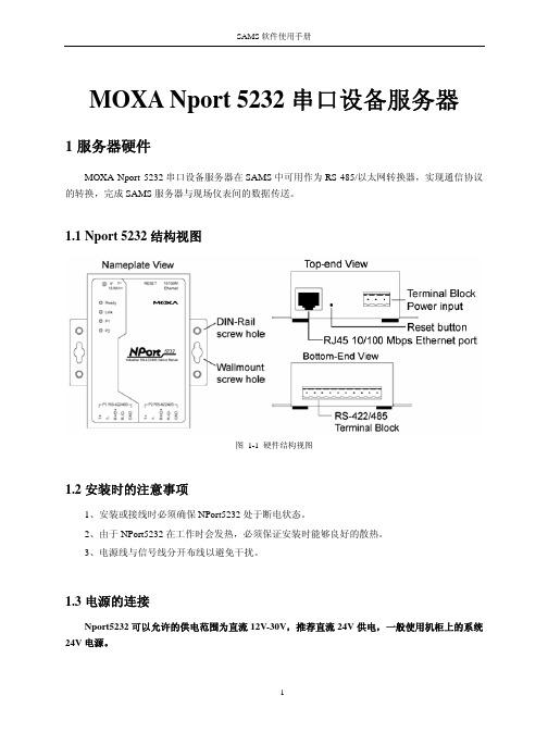
MOXA Nport 5232串口设备服务器1服务器硬件MOXA Nport 5232串口设备服务器在SAMS中可用作为RS-485/以太网转换器,实现通信协议的转换,完成SAMS服务器与现场仪表间的数据传送。
1.1Nport 5232结构视图图 1-1 硬件结构视图1.2安装时的注意事项1、安装或接线时必须确保NPort5232处于断电状态。
2、由于NPort5232在工作时会发热,必须保证安装时能够良好的散热。
3、电源线与信号线分开布线以避免干扰。
1.3电源的连接Nport5232可以允许的供电范围为直流12V-30V,推荐直流24V供电,一般使用机柜上的系统24V电源。
图 1-2 电源接线端子注意:V+接电源正,V-接电源负,屏蔽地SG需接保护地。
1.4RS-485口的连接Nport5232的Port口端子定义如下:图 1-3 Nport5232端子定义Nport5232共有2个RS-422/RS-485接口,在连接RS-485时RS-485正接Data+,RS-485负接Data-。
1.5指示灯表 1-1 NPort 5232 指示灯定义指示灯指示灯颜色表示的含义Ready红常亮:模块正在启动闪烁:检测到IP地址冲突,或者DHCP与BOOTP服务器没有正确回应绿常亮:模块已上电且功能正常闪烁:模块被定位灭没有供电或供电异常Ethernet橙 10M以太网连接绿 100M以太网连接灭网络未被连接橙串口正在接收数据P1,P2绿串口正在发送数据灭串口上没有收发数据1.6网络的连接NPort5232的以太网网口连接到SAMS服务器所在网络。
2服务器软件配置在SAMS数据服务软件中配置通讯服务器之前,须先通过NPort Administrator Suite软件进行串口配置。
2.1串口设备服务器的基本设置点击[开始/NPort Administrator Suite/NPort Administrator],弹出图 2-1所示界面。
- 1、下载文档前请自行甄别文档内容的完整性,平台不提供额外的编辑、内容补充、找答案等附加服务。
- 2、"仅部分预览"的文档,不可在线预览部分如存在完整性等问题,可反馈申请退款(可完整预览的文档不适用该条件!)。
- 3、如文档侵犯您的权益,请联系客服反馈,我们会尽快为您处理(人工客服工作时间:9:00-18:30)。
第一章:准备工作准备工作我们用一条交叉网线把NPort5110 和PC机的网口连接起来,并把NPort上电。
首先,打开控制面板,网络连接。
在本地连接上点右键,选择属性。
双击进入Internet协议(TCP/IP),点击“使用下面的IP地址”写入IP 地址和子网掩码,记住要和NPORT 的IP 地址在同一子网段内。
如NPORT 默认IP为;就需要把PC 机的IP 地址设为,,最后一个数字不同即可。
点击确定。
第二章:网络和串口参数配置搜索NPort打开NPort Administrator(可以在光盘的对应位置找到这个软件,安装好),点击Search,此时请确认网络防火墙已经关闭。
会搜索到我们的NPort5110,点击stop,停止搜索。
网络参数配置双击右边空白处的NPort 设备,会出现以下界面,点击选择Network 选项卡,点击Modify修改。
可以看到以下界面:我们可以在里面修改NPort的以下参数:IPAddress:IP地址。
Netmask:子网掩码。
Gateway:网关。
IP Configuration:可以配置为静态IP(Static),或者为DHCP(动态IP)。
DNS Server1和2:DNS,域名解析服务器。
串口参数配置点击Serial选项卡,点击Modify修改,双击端口进去,可以看到以下界面:我们可以在里面修改以下参数:Baud Rate:波特率,NPort5000 系列只能支持标准波特率,如9600,115200bps 等。
Parity:校验。
None:无校验Even:偶校验。
Odd:奇校验。
Space:空。
Mark:标志。
Data Bits:数据位。
Stop Bits:停止位。
Flow Control:流量控制。
None:无流量控制。
XON/XOFF:软件流控。
RTS/CTS:硬件流控。
FIFO:64bit先进先出,为了降低CPU负载,提高设备性能。
可以选择Enable启用,或Disable禁用。
Interface:可选择RS232,RS422,RS485 2线,或者RS485 4线。
(NP5110 只能为RS232)设置好后,点击OK,设置保存,设备重新启动。
第三章:操作模式设置Real COM映射端口打开NPort Administrator(可以在光盘的对应位置找到这个软件,安装好),点击Search,此时请确认网络防火墙已经关闭。
会搜索到我们的NPort5110,点击stop,停止搜索。
双击右边的5110,选择Operating Mode选项卡,确认为Real COM模式:点击左边的第四项:COM MAPPING,再点击Add点击“OK”,点击“Apply”保存点击“Yes”,点击“OK”。
这样,端口就映射好了。
TCP Server模式的设置(用软件)打开NPort Administrator(可以在光盘的对应位置找到这个软件,安装好),点击Search,此时请确认网络防火墙已经关闭。
会搜索到我们的NPort5110,点击stop,停止搜索。
如果打开防火墙,可以使用Search IP,在下面选项框里输入NPort的IP地址,点击OK,就可以搜索到NPort设备。
双击右边的NP5110,切换到OperatingMode选项卡,点击Modify,双击进去。
可以把模式修改成TCP Server 模式。
里面的名词解释:Local TCP Port:本地数据端口,指的是NP5110 的数据端口。
Command Port:NP5110 的命令端口。
Max Connection:最大连接数,也就是说同时最大可以有几台上位机采集到下面串口设备的数据,NPort5000 系列最大是4 个,NPort6000 和CN2600 系列是8 个。
当最大连接数为2 或以上的时候,右边的选项Allow Driver Control 和Ignore Jammed IP会开启。
Allow Driver Control:当最大连接数为2 或以上时,且此功能打开时,上位机A 需要以4800bps打开串口,上位机B需要以9600bps打开串口,是可以的。
如果此功能关闭,则波特率需以固件中的设置一致。
Ignore Jammed IP:当最大连接数为2 或以上时,且此功能打开时,其中一台上位机A死机,上位机B 依然可以正常接收数据。
如果此功能关闭,则上位机B 也不能收到串口的数据了。
所以在最大连接数为2或以上时,必须打开此功能。
TCP Alive Check Time:默认是7分钟,也就是说每7 分钟会检查一次TCP连接,如果连接不成功,则断开TCP连接。
可以这么理解,如果TCP连接已经断开,在7 分钟之内,NPort仍然认为连接存在,在7 分钟的时候,它向上位机发送一个错误的TCP 包,如果上位机回复它,说你错了,则NPort认为连接依然存在;如果没有回复,则NPort把TCP连接断开。
Inactivity Timeout:默认是0,此功能关闭。
如果是10ms,也就是说如果串口10ms 内没有收到数据,则TCP连接就断开。
Delimiter1:界定符1,16进制表示,如0x41 是A,0x61 是a。
Delimiter2:界定符2,16进制表示,如0x41 是A,0x61 是a。
当界定符1被Enable的时候,1 起作用;当1 和2都被允许的时候,1和2 都起作用。
例如界定符1 是a,界定符2是b,1 和2 都是Enable,则界定符为ab。
Force Tx Timeout:强制传输时间,至少大于1 个字符的传输时间。
例如,串口波特率为1200,n,8,1。
需要传送一个10bit的数据,则时间是:(10bit/1200bps)×1000(s/ms)=。
所以强制传输时间必须至少大于这个值。
Packing Length:TCP打包长度,以字节byte为单位。
Delimiter Process:界定符控制。
Start/None:前面一部分表示什么时候建立连接,后面一部分表示什么时候断开连接。
对于这个例子也就是说,一开机就建立连接,并且一直保持连接。
Any Character/None:串口接到任何字符就建立连接,并且一直保持连接。
Any Character/Inactivity Time:串口接到任何字符就建立连接,在达到Inactivity Time的限制时断开连接。
ASCII码对照表:下表列出了字符集中的0 - 127。
下表列出了字符集中的128 - 255。
** 数值8、9、10 和13 可以分别转换为退格符、制表符、换行符和回车符。
这些字符都没有图形表示,但是对于不同的应用程序,这些字符可能会影响文本的显示效果。
"空" 表示在当前平台上不支持的字符。
TCP Client 模式设置Destination Host:为目标地址,也就是NPort5110 去连接的Server 的地址。
:为目标端口,也就是NPort5110 去连接的Server 的端口号。
Local Port:NP5110的本地数据端口。
Ignore Jammed IP:当最大连接数为2 或以上时,且此功能打开时,其中一台上位机A死机,上位机B 依然可以正常接收数据。
如果此功能关闭,则上位机B也不能收到串口的数据了。
所以在最大连接数为2或以上时,必须打开此功能。
TCP Alive Check Time:默认是7分钟,也就是说每7 分钟会检查一次TCP连接,如果连接不成功,则断开TCP连接。
可以这么理解,如果TCP连接已经断开,在7 分钟之内,NPort仍然认为连接存在,在7 分钟的时候,它向上位机发送一个错误的TCP 包,如果上位机回复它,说你错了,则NPort认为连接依然存在;如果没有回复,则NPort把TCP连接断开。
Inactivity Timeout:默认是0,此功能关闭。
如果是10ms,也就是说如果串口10ms 内没有收到数据,则TCP连接就断开。
Delimiter1:界定符1,16进制表示,如0x41 是A,0x61 是a。
Delimiter2:界定符2,16进制表示,如0x41 是A,0x61 是a。
当界定符1被Enable的时候,1 起作用;当1 和2都被允许的时候,1和2 都起作用。
例如界定符1 是a,界定符2是b,1 和2 都是Enable,则界定符为ab。
Force Tx Timeout:强制传输时间,至少大于1 个字符的传输时间。
例如,串口波特率为1200,n,8,1。
需要传送一个10bit的数据,则时间是:北京时代佳业李纯制作第25 页共31 页(10bit/1200bps)×1000(s/ms)=。
所以强制传输时间必须至少大于这个值。
Packing Length:TCP打包长度,以字节byte为单位。
Delimiter Process:界定符控制。
Start/None:前面一部分表示什么时候建立连接,后面一部分表示什么时候断开连接。
对于这个例子也就是说,一开机就建立连接,并且一直保持连接。
Any Character/None:串口接到任何字符就建立连接,并且一直保持连接。
Any Character/Inactivity Time:串口接到任何字符就建立连接,在达到Inactivity Time的限制时断开连接。
ASCII码对照表:下表列出了字符集中的0 - 127。
下表列出了字符集中的128 –255** 数值8、9、10 和13 可以分别转换为退格符、制表符、换行符和回车符。
这些字符都没有图形表示,但是对于不同的应用程序,这些字符可能会影响文本的显示效果。
"空" 表示在当前平台上不支持的字符。
UDP模式Local Listen Port:为NPort5110 的本地数据端口。
下面的Destination Begin End:为UDP发送数据的目标地址段。
Port:目标端口号最多四组。
Delimiter1:界定符1,16进制表示,如0x41 是A,0x61 是a。
Delimiter2:界定符2,16进制表示,如0x41 是A,0x61 是a。
当界定符1被Enable的时候,1 起作用;当1 和2都被允许的时候,1和2 都起作用。
例如界定符1 是a,界定符2是b,1 和2 都是Enable,则界定符为ab。
Force Tx Timeout:强制传输时间,至少大于1 个字符的传输时间。
例如,串口波特率为1200,n,8,1。
需要传送一个10bit的数据,则时间是:(10bit/1200bps)×1000(s/ms)=。
所以强制传输时间必须至少大于这个值。
Packing Length:TCP打包长度,以字节byte为单位。