SP3D学习笔记
SmartPlant3D_SP3D软件基础操作
SmartPlant3D_SP3D软件基础操作SmartMarine 3DCommon Applications LabsVersion 7.3October 2007CopyrightCopyright ? 2007 Intergraph Corporation. All Rights Reserved. Including software, file formats, and audiovisual displays; may be used pursuant to applicable software license agreement; contains confidential and proprietary information of Intergraph and/or third parties which is protected by copyright law, trade secret law, and international treaty, and may not be provided or otherwise made available without proper authorization.Restricted Rights LegendUse, duplication, or disclosure by the Government is subject to restrictions as set forth in subparagraph (c) of the Contractor Rights in Technical Data clause at DFARS 252.227-7013, subparagraph (b) of the Rights in Computer Software or Computer Software Documentation clause at DFARS 252.227-7014, subparagraphs (b)(1) and (2) of the License clause at DFARS 252.227-7015, or subparagraphs (c) (1) and (2) of Commercial Computer Software--Restricted Rights at 48 CFR 52.227-19, as applicable. Unpublished---rights reserved under the copyright laws of the United States. Intergraph Corporation Huntsville, Alabama 35894-0001Warranties and LiabilitiesAll warranties given by Intergraph Corporation aboutequipment or software are set forth in your purchase contract, and nothing stated in, or implied by, this document or its contents shall be considered or deemed a modification or amendment of such warranties. Intergraph believes the information in this publication is accurate as of its publication date. The information and the software discussed in this document are subject to change without notice and are subject to applicable technical product descriptions. Intergraph Corporation is not responsible for any error that may appear in this document. The software discussed in this document is furnished under a license and may be used or copied only in accordance with the terms of this license. No responsibility is assumed by Intergraph for the use or reliability of software on equipment that is not supplied by Intergraph or its affiliated companies. THE USER OF THE SOFTWARE IS EXPECTED TO MAKE THE FINAL EVALUATION AS TO THE USEFULNESS OF THE SOFTWARE IN HIS OWN ENVIRONMENT.TrademarksIntergraph, the Intergraph logo, SmartSketch, FrameWorks, SmartPlant, INtools, MARIAN, and PDS are registered trademarks of Intergraph Corporation. Microsoft and Windows are registered trademarks of Microsoft Corporation. MicroStation is a registered trademark of Bentley Systems, Inc. ISOGEN is a registered trademark of Alias Limited. Other brands and product names are trademarks of their respective owners.Table of ContentsTable of ContentsLAB-1: Session File, Tasks, View and Window Management.................................... 4 LAB-2A: Filter Management –System ....................................................................... 8 LAB-2B: Filter Management –Object type (15)LAB-2C: Filter Management –Volume Filter........................................................... 17 LAB-2D: Filter Management – Properties (Optional Lab) . (20)LAB-2E: Filter Management –Properties (Optional Lab) ........................................ 26 LAB-2F: Filter Management –Properties (Optional Lab)......................................... 31 LAB-2G: Filter Management – Properties (Optional Lab) . (34)LAB-3: Creating Surface Style Rule.......................................................................... 37 LAB-4: Work Break Down Structure ........................................................................ 40 LAB-5: Inserting Control Points ................................................................................42 LAB-6: Tool Tip Editing ( Optional lab)................................................................... 44 LAB-7: SQL Filter (This lab is for Advance users only). (47)SmartMarine 3D Common Applications Labs 3Common ApplicationsLAB-1: Session File, Tasks, View and Window Management ObjectiveAfter This Lab Students will be able to Create a session file, modify settings, setup views and move around in a model Lecture: Instructor Needs to explain session template, session file, tasks, options, views and view manipulations 1 2 Start SmartMarine 3D using Start –Programs –Intergraph SmartMarine 3D –SmartMarine 3D. From the New dialog box, select the Empty template and click OK3From the Tasks menu, select Configure Task List4 SmartMarine 3D Common Applications LabsCommon Applications4 5 6 7 8 9Select all tasks from the left side and click Add. Then click OK. Now select Common from the Tasks menu. From the Window menu, select New Window three times such that four windows are open. From the Window menu select Tile Horizontally. Activate GraphicView1 by clicking in its title bar. From the named views pulldown on the Common toolbar, select Front.10 Similarly set GraphicView2 to Top, GraphicView3 to Right and GraphicView4 to Isometric. 11 Select Tools , Options to bring up the Options dialog box. 12 On the units of measure tab, select ft-in for distance.SmartMarine 3D Common Applications Labs 5Common Applications13 On the SmartSketch tab, set the dwell time for stack = 0.1 Seconds 14 Select file, Save as and save the session file on your desktop For SmartMarine 3D Setup and Admin class: This session file can be saved as session template. To save this as template, Select File menu, Save As and save this session template in \ProductDir\CommonApp\SessionT emplates\General The location for the Session Templates can be changed using the Tools->Option dialog box. Open this dialog and select the File Locations Tab. You can change this location to a UNC path and store all your session templates there.6 SmartMarine 3D Common Applications LabsCommon Applications 15 Select File menu –> DefineWorkspace16 Select the available training Ship 17 Under filters, select more to open the Select Filter dialog 18 Expand the Ship Filters folder, Select all filter and Ok on the form19 Ok on the define Workspace Form and Fit all views 20 Practice Different View Manipulation CommandsSmartMarine 3D Common Applications Labs 7Common ApplicationsLAB-2A: Filter Management – SystemObjectiveAfter This Lab Students will be able to Create and or display different type of filters Lecture: Instructor Needs to explain filter creation, display, modify and selection. 1 Select File, Define Workspace2 3 4 5 6Select More… to open the Select Filter dialog Expand the Ship Filters folder, Select all filter and Ok on the form Ok on the define Workspace Form and Fit all views Select File, Define Workspace or CTRL W, select more… Select My Filters folder, Select the Simple Filter Icon to open The New Filter Properties dialog box.8 SmartMarine 3D Common Applications LabsCommon Applica tions 7 8 9 Name the filter “Unit 1” Select Area2 , Unit 1 on the System Tree to select objects Expand Coordinate Systems by clicking on the + sign. Note: Do NOT click the name ‘Coordinate System’10 Press and hold the Ctrl key on the keyboard and select Unit 1 CS. 11 Click OK to accept the filter definition.12 Select the filter “Unit 1” 13 Click OK to accept the selected filter 14 Click OK to bring all Unit1 objects into the workspace.SmartMarine 3D Common Applications Labs 9Common Applications 15 Your View should now resemble the following graphic.16 Select Define Workspace or CTRL W, select more (17)Select My Filters folder, Select the Simple Filter Icon to open The New Filter Properties dialog box. 18 Name the filter “Unit 2”. Select Unit 2 on the System Tree to select objects 19 Expand Coordinate Systems by clicking on the + sign. Note: Do NOT click the name ‘Coordinate System’ 20 Press and hold the Ctrl key on the keyboard and select Unit 2 CS. Click OK to accept the filter definition. 21 Select th e filter “Unit 2”. Click OK to accept the selected filter. 22 Select OK to bring all Unit 2 objects into the workspace10 SmartMarine 3D Common Applications LabsCommon Applications23 Create a new Simple Filter named Building 1, to include Building 1 and Building 1 CS.SmartMarine 3D Common Applications Labs 11Common Applications 24 Create a new Simple Filter named Amines Unit, to include Amines Unit and Amines Unit CS 25 Create a new Simple Filter named Unit 1 & Unit 2, to include Unit 1, Unit 2, Unit 1CS and Unit 2 CS12 SmartMarine 3D Common Applications LabsCommon Applications 26 Your view should resemble this27 Create a new Simple filter Building 1 & Unit 2, to include Building 1, Unit 2, Building 1 CS and Unit 2 CS28 Select Define Workspace and select Unit 1 to Display all objects in Unit 1SmartMarine 3D Common Applications Labs 13Common Applications14 SmartMarine 3D Common Applications LabsCommon ApplicationsLAB-2B: Filter Management – Object type(Delivered Filters – Selection only)After This Lab Students will be able to select objects using object type filters Lecture: Instructor Needs to explain selection of objects using different filters. Also explain/show delivered catalog filters 1 2 3 4 5 Display Unit 1 if not already displayed Select Tools, Select by Filter command to open the Select Filter dialog box. Under Catalog filters, expand Default Filters, SMARTMARINE 3D Object Filters, Object Types and select Structure(select structure filter not the folder) Click OK to select all Structural objects in Displayed filter Your View should now resemble the following graphic.6Select Tools, Hide7Your view should resemble thisSmartMarine 3D Common Applications Labs 15Common Applications8 9Select tools, show all Select T ools, Select by Filter command to open the Select Filter dialog box.10 Under Catalog filters, expand Default Filters, SmartMarine 3D Object Filters, Object Types and select Cableway(select Cableway filter not the folder) 11 Click OK to select all Cableway objects in Displayed filter 12 Select Format Styles, Under Surface Tab select Green Color and select Apply Button 13 System will change all Electrical Objects to Green Color. Note: To change the Cableway back to original color, select cableway objects using same filter, select format - Styles and Select Apply Style by Rule and apply16 SmartMarine 3D Common Applications LabsCommon ApplicationsLAB-2C: Filter Management – Volume FilterObjectiveAfter This Lab Students will be able to Create and/or display filters based on Volumes Lecture: Instructor Needs to explain Volume filter creation, display, modify and selection.1 2 3 4 5 6 7 8Select define WorkSpace and select more Select the My Filters folder Select the Simple Filter Icon to open The New Filter Properties d ialog box Name the filter “Volume Unit 1” Select Ship name on Systems Tab Open Names Space Tab. Open the Layout volume by Clicking on + sign Select Volume Unit 1 Open the Volume Tab, and select Volume Unit 1SmartMarine 3D Common Applications Labs 17Common Applications 9 Click OK10 Select Volume Unit 1 and OK 11 Ok on the define Workspace Form 12 Your view should resemble this13 System display Volume Unit 1, and all objects which are fully or partially inside the volume 14 To display objects only within the volume, select the volume and use clip by objects. Select the Volume(box) and do tools hide.18 SmartMarine 3D Common Applications LabsCommon Applications15 Select Tools->Show All to displays all objects again. Go to View->Clear Clipping to remove the clipped volume. 16 Create a new Filter name Volume Unit 2, to include Shipname from Systems tab, Volume unit 2 from Named space tab and Volume Unit 2 from Volume tab 17 Display Volume Unit 2. Now select the volume unit 2 from space tab on workspace explorer, and clip by object. Hide the Volume box.18. Select Tools->Show All to displays all objects again. Go to View->Clear Clipping to remove the clipped volume SmartMarine 3D Common Applications Labs 19。
对三维设计软件PDMS与SP3D的应用相关解析
30一、三维设计软件PDMS与SP3D的概述三维设计工作就是利用三维设计软件进行相应的数据、理论形式下的三维模型建造工作。
从而以一种直观的方式来表现实际的程序化、智能化、参数化形态的展示工作;使人们可以在更为直观的角度下去观察其形态、工艺、流程的具体展示,从而形成一个关于项目的数据集成管理平台系统。
PDMS软件:其是三维系统下主要支撑软件,其包括了各种功能模块:项目管理、应用模块;设计、分析、出图模块以及相应的元件库以及等级库模块等。
在其中我们最为熟悉的就是关于工艺、设备、管道以及相应的土建工程的计算模式。
在实际的三维模型设计中就有极其显著的作用。
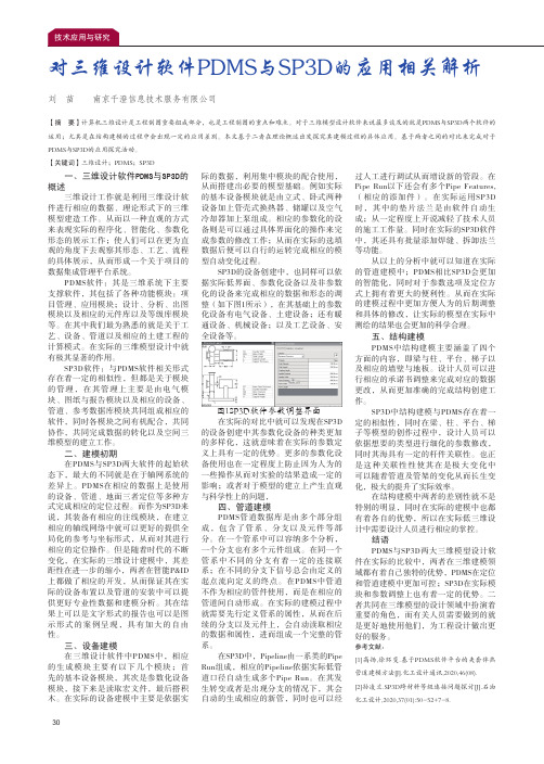
SP3D软件:与PDMS软件相关形式存在着一定的相似性,但都是关于模块的管理,在其管理上主要是由电气模块、图纸与报告模块以及相应的设备、管道、参考数据库模块共同组成相应的软件,同时各模块之间有机配合,共同协作,共同完成数据的转化以及空间三维模型的建立工作。
二、建模初期在PDMS与SP3D两大软件的起始状态下,最大的不同就是在于轴网系统的差异上。
PDMS在相应的数据上是使用的设备、管道、地面三者定位等多种方式完成相应的定位过程。
而作为SP3D来说,其装备有相应的注线模块,在建立相应的轴线网络中就可以更好的提供全局化的参考与坐标形式,从而对其进行相应的定位操作。
但是随着时代的不断变化,在实际的三维设计建模中,其差距性在进一步的缩小,两者在智能P&ID 上都做了相应的开发,从而保证其在实际的设备布置以及管道的安装中可以提供更好专业性数据和建模分析。
其在结果上可以是文字形式的报告也可以是图示形式的案例呈现,具有加大的自由性。
三、设备建模在三维设计软件中PDMS中,相应的生成模块主要有以下几个模块;首先的基本设备模块,其次是参数化设备模块,接下来是读取宏文件,最后搭积木。
在实际的设备建模中主要是依据实际的数据,利用集中模块的配合使用,从而搭建出必要的模型基础。
杂化轨道理论

杂化轨道理论杂化轨道理论基本介绍核外电子在一般状态下总是处于一种较为稳定的状态,即基态。
而在某些外加作用下,电子也是可以吸收能量变为一个较活跃的状态,即激发态。
在形成分子的过程中,由于原子间的相互影响,单个原子中,具有能量相近的两个电子亚层中,具有能量较低的电子亚层的一个或多个电子会激发而变为激发态,进入能量较高的电子亚层中去,即所谓的跃迁现象,从而新形成了一个或多个能量较高的电子亚层。
此时,这一个与多个原来处于较低能量的电子亚层的电子所具有的能量增加到与原来能量较高的电子亚层中的电子相同。
这样,这些电子的轨道便混杂在一起,这便是杂化,而这些电子的状态也就是所谓的杂化态。
概述1931年,Linus Carl Pauling提出轨道杂化理论。
实验事实基础是许多分子的键角不等于原子轨道间夹角。
如氧原子与氢原子组成的水分子H-O-H的键角是104.5o,不等于氧的2py与2pz轨道间的夹角90o。
类似的,NH3分子中H-N-H的键角也不等于90o,实际测得107.3o。
实验测得甲烷分子CH4是四面体结构,H-C-H键角为109.5o。
要点⑴ 在形成分子(主要是化合物)时,同一原子中几个能量相近的不同类型的原子轨道 (一般为同一能级组的原子轨道)可以进行线性组合(杂化),重新分配能量和确定空间方向,组成数目相等的新的一组原子轨道。
⑵杂化轨道成键能力大于原来的原子轨道。
因为杂化轨道的形状变成一头大一头小了,用大的一头与其他原子的轨道重叠,重叠部分显然会增大。
⑶ 形成的杂化轨道之间应尽可能地满足最小排斥原理(化学键间排斥力越小,体系越稳定),为满足最小排斥原理,杂化轨道之间的夹角应达到最大。
⑷ 分子的空间构型主要取决于分子中σ键形成的骨架,杂化轨道形成的键均为σ键,所以,杂化轨道的类型与分子的空间构型相关。
相关概念在形成多原子分子的过程中,中心原子的若干能量相近的原子轨道线性组合成新的原子轨道,这个过程叫做原子轨道的杂化,产生的新轨道叫做杂化轨道。
SP3D非金属数据库设计及应用

SP3D非金属数据库设计及应用作者:孙凌兰来源:《中国化工贸易·中旬刊》2018年第05期摘要:以SP3D为代表的三维设计集成软件在工程项目的金属材料中得到了成熟且广泛的应用,该软件是以材料等级库为基础进行三维建模设计的。
随着近年来涉及污水处理、市政自来水、消防给排水等选用非金属材料的项目越来越多,非金属材料等级库的成熟设计显得尤为迫切。
SPRD(SmartPlant Reference Data)即智能工厂的参考数据库软件,用于创建、维护公司级和项目级的材料编码库、标准尺寸库、管道等级库,并能够针对SP3D的接口程序为该设计系统提供非金属材料等级数据。
本文介绍了基于SPRD非金属材料等级库的建库过程,并对照SP3D手动建库进行了比对分析,给出了该软件在非金属材料工程中的应用及非金属材料等级库的维护和质量控制措施。
关键词:SP3D;数据库设计1 前言目前,以SP3D为代表的三维设计集成软件在工程项目的金属材料中得到了成熟且广泛的应用,该软件是以材料等级库为基础进行三维建模设计的。
随着近年来涉及污水处理、市政自来水、消防给排水等选用非金属材料的项目越来越多,非金属材料等级库的成熟设计显得尤为迫切。
2 SPRD非金属材料建库的内容SPRD建库的工作应在非金属材料等级规定发布之后进行,并为集成设计软件SP3D的配管设计做准备。
SPRD非金属材料建库的来源和依据,SP3D非金属材料库建库的来源和依据为非金属材料等级规定,首先要了解材料等级说明,管道、管件和法兰要求,包括具体设计选用的执行标准、材料要求、连接形式及结构特点,然后根据非金属材料等级表在SPRD中进行管子和管件的材料建库工作。
非金属材料等级表中包括了SPRD建库所需要的表头信息、组成材料编码的要素、尺寸数据的来源及尺寸范围等必要信息。
通过SPRD建库,将材料等级表中的材料信息录入到SPRD软件的数据库中。
3 SPRD建库与3D手动建库的特点与比较SP3D集成设计软件的材料库建库分为SPRD建库和3D手动建库两种,这两种建库方式只是建库方法的不同,其实现的结果是完全相同的。
关于PMDS和SP3D中间格式应用和转换说明

PDMS模型中间格式说明一、PDMS模型导出方法⏹RVM格式文件导出Utilities-Export-Create⏹RVM格式导出设置1、设置文件访问路径,注意文件格式(如:D:\MOD.RVM)2、选择设置RVM格式模型的文本制式3、添加导出模型4、添加制定配色文件5、确认导出二、导出att属性文件⏹ATT格式文件导出Utilities-Export-Dump Attributes⏹att格式导出设置1、选择需要导出的模型2、设置导出存放路径(如:D:\MOD.ATT)3、确认导出三、PDMS模型文件说明和注意⏹PDMS模型根据需求可以设置导出细致成度(值越低效果越好,响应导出模型数据就越大)⏹在导出模型前应检查项目内设单位(常用毫米MM)⏹RVM和ATT格式应用用于EDIS模型交互、也用于目前可视化模型优化处理参考模版SP3D模型中间格式说明一、SP3D模型导出方法(方法有几种,以下举例常用的方法)⏹模型文件导出窗口Tools-Drawing Console⏹在出现的对话窗口右击新建文件,并在该文件下创建3D Modle Data⏹右击3D Modle Data设置Setup1、设置导出模型Filter2、设置导出模型格式(目前支持VUE +XML和sat两种文件)3、选择存放路径(注:VUE文件需要两个都需要设置,SAT 只需设置前一个)4、确认导出二、SP3D模型格式说明⏹VUE+XML模型目前只能用SP3D配套的review阅览软件打开(也可以用于SPF发布,但需要配套的发布软件)⏹SAT模型可以用第三方软件打开如Naviswork 3DMAX等,目前用于三维可视化模型优化参考模型(由于属性和模型数据大小问题,建议将模型拆分命名导出,管线以管线号为单位、机械以设备位号为单位、其他可按照区域专业导出)。
SP3D操作
SP3D在管道设计中的常见错误提示与解决方案

SP3D在管道设计中的常见错误提示与解决方案
SP3D是一款广泛应用于管道设计的三维设计软件。
在使用SP3D进行管道设计和模拟
过程中,会遇到各种各样的错误提示。
这些错误可能导致设计不符合标准、影响工程进度
和成本,甚至会引发安全隐患。
及时解决SP3D中的错误提示是非常重要的。
下面我们将针对SP3D在管道设计中常见的错误提示进行分析,并提供解决方案。
1. 错误提示:管道连接错误
解决方案:检查管道连接的位置和方向是否正确。
可能需要重新调整管道连接点的位
置或者调整管道的方向,保证管道连接正确无误。
解决方案:检查管道尺寸是否符合设计要求。
可能需要重新设置管道的尺寸参数,确
保符合设计规范。
解决方案:检查管道模型是否完整,可能需要重新绘制管道模型或者修复缺失的部分,确保管道模型完整无误。
5. 错误提示:管道设计不符合标准
解决方案:进行管道碰撞检测,发现管道之间或者管道与其他设备之间发生碰撞时,
可能需要进行管道重定位或者调整管道轨迹,确保不发生碰撞。
解决方案:检查材料库,可能需要更新或者添加相关材料,确保材料库中的信息齐全
和准确。
8. 错误提示:工程图纸制作错误
解决方案:检查工程图纸制作的参数是否正确,可能需要对制图参数进行调整,确保
工程图纸能够准确呈现设计内容。
SP3D overview
1 Intergraph鹰图公司背景介绍Intergraph公司市场占有率INTERGRAPH公司创建于1969年,总部设在美国阿拉巴马(Alabama)州亨茨维尔(Huntsville)市,有着近40年的发展历史。
Process Power & Marine (PPM)化工—电力—海事,作为INTERGRAPH 的一个部门有员工近1300人,其中1,000多名从事软件开发,技术服务和支持。
2008年营业额超过3亿4000万美元。
INTERGRAPH公司在中国拥有大量用户,早在1984年就在北京设立办事处,目前在北京和上海有办公室。
鹰图中国有限公司有员工50多名,另外还拥有近100名员工的数据转换中心和技术服务部也设在北京。
能为中国用户提供良好的技术服务和支持。
Intergraph的旗舰产品: 三维工厂设计软件SmartPlant 3D介绍SmartPlant 3D作为最先进的工厂设计软件,是Intergraph推出的新一代的,面向数据的,规则驱动的更符合工程设计流程的软件,同时已保存的数据可以更好的使用/复用。
SmartPlant 3D以MS SQL和Oracle为基础数据库,所有模型都是以对象形式存在基础数据库中。
并且不需要其他的图形引擎,使用较易使用的Visual Basic作为开发软件。
SmartPlant 3D是一个前瞻性的产品,它改变了工程设计的方式。
它打破了传统设计技术的局限。
比起注重简单的完成工厂设计,SmartPlant 3D有效的使设计优化,提高效率,缩短了项目周期。
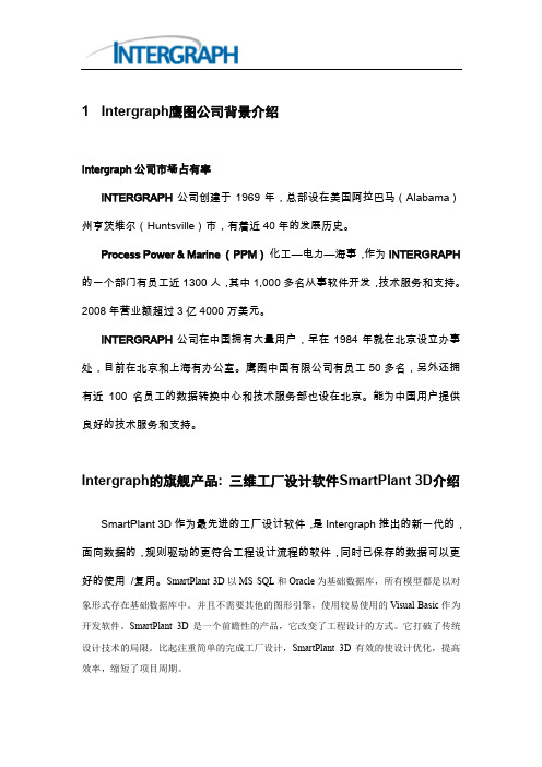
SmartPlant 3D 的数据结构图如下:通过定义过滤器方式建立“工作集”,所有文件存储在数据库中,真正实现了面向对象,避免了寻找设计文件的设计浪费。
SmartPlant 3D 操作界面如下:Site Database:记录工厂和参考数据库的名称, 以及与其相关联的模型和报告的数据库的名称。
Catalog Database: 存储所有专业使用的参考数据Model Database: 记录设计信息Report Database :采集工厂,地点和参考数据库的映像,用于生成各类报告。
- 1、下载文档前请自行甄别文档内容的完整性,平台不提供额外的编辑、内容补充、找答案等附加服务。
- 2、"仅部分预览"的文档,不可在线预览部分如存在完整性等问题,可反馈申请退款(可完整预览的文档不适用该条件!)。
- 3、如文档侵犯您的权益,请联系客服反馈,我们会尽快为您处理(人工客服工作时间:9:00-18:30)。
三维软件学习笔记
一、单管图图框设置操作步骤:
a、TOOLS下的OPTIONS中设置好两软件文字对应关系;
b、用Smartsketch打开采用AUTOCAD绘制好的图框文件,调好版面上文字样式及大小;
c、TOOLS下的OPTIONS中设置好单位;
d、在VIEWS下选择BACKGROUD SHEETS,设置好对应大小的SHEET SETTUP,然后将图框复制过去;
e、然后切换至WORKING SHEETS,新建对应大小的SHEET SETTUP
此步Name下必须修改为SHEET1
f、在SHEET下保存文件为.SHA文件。
g、在下面路径中找到\Program Files(x86)\Smart3D\CatalogData\Bulkload\Datafiles找到bulkloadisokeys.xls文件,打开复制一列,将名称全部对应修改为要添加的图框名称。
采用BULKLOAD下。
h、将a-f步骤创建的图框拷在项目共享文件\\win-v6n6pvm43e2\SharedContent\PmfgIsoStyleData下,然后拷一个相应大小的XML 文件,(COOKTOP2.5打开)将该XML文件中的图框名字对应修改为新建图框的名字,然后保存。
I、ISOGEN设置时,文字报错,修改文字设置如下。
j 、在DRAWING AND REPORTS 模式下新建ISO 文件夹,然后在ISO 文件夹下新建如下图的内容,
k 、存储风格包,如下图,选择SAVE Package 。
选择下面的pipeline
l、选中新建的风格包,右键选SETUP,新建Filter时选择好处图范围,如下图。
m、然后选中风格包,右键新建图纸,如下图,最后UPDATE NOW即可完成ISO图出图。
备注:平面图图框
二、PID中项目备份及恢复操作步骤;
a、项目备份:首先打开SMARTPLANT ENGINEERING MANAGER,然后选择具体项目,在TOOLS下选择BACKS,操作步骤如下图。
b、恢复项目:首先打开SMARTPLANT ENGINEERING MANAGER,然后选择站点,在TOOLS 下选择RESTORE,操作步骤如下图。
在INPORT FILE下面找到备份数据ZIP文件夹。
输入备份密码(备份密码为建项目时在数据库中设置的密码)。
在第三步时需更改具体对应的路径。
三、PID中设置绘图规则在intergraph SmartPlant P&ID中选择Options Manager进行设置。
四、PID中自动断管,可设置画图时自动断管AutoGap,也可画完后在Gap Now。
如下图设置,画图时选择。
五、pid中法兰在Piping下Fitting中的Flanges and Unions里面。
选择要创建的图形,然后在FILE下点击SAVE AS Assembliy,确定保存的路径即可。
六、更改管径显示样式操作步骤如下,
七、SPRD授权操作步骤
八、PID建立ASSEMBLIES时应将所有物件属性及参数填写完整。
PID中复制粘贴管件属性详见下图。
九、设备材料报表定制
A、新建报表文件REPORTS,步骤如下图。
B、新建报表,详见下图。
先选择复制源属性管件,然后点此按钮复制
然后选择需要填属性的管件,然后点此按钮粘贴
C、编辑模板。
详见下图
D、在TOOLS下点击ADD QUERY,详见下图
E、报表中各属性提取编辑详见下面设备及管件报表截取步骤。
1、管件报表
2、设备报告
注意事项:创建滤镜时应选对位置。
十、三维软件中自定义LABLE路径如下。
备注:最好新建CUSTOM,放置在该文件下
十一、取消坡度管时应确保角度不被锁死。
十二、SPRD创建等级库
1、元件跟管道连接端在SPRD中要用MATCH,见下图。
十三、报表定制
SQL查询
选择项目的RDB文件,鼠标右键选择NEW QUERY
C:\Program Files (x86)\Smart3D\Core\Tools\Administrator\Bin下找到MetaDataBrowser
查看接口名字
属性
层级关系
访问接口
1、要将模板存储到CATLOG,必须确保所建过滤器在CATLOG FILTER下。
2、在编辑报表样式时,常量里面可以直接输LABEL,使用方式为[LABEL名]。
序号连续应勾该项
3、
十四、项目备份方法。
相关线处理
图面预处理规则
控制图面方向
控制视图边界
十五、出平面图
1、创建视口,如下图,切换视口方向选取出图区域。
创建视口
2、新建NEW COMPOSED DRAWINGS,
3、
选取第2部创建的4、
2d3d校对
4、NPD为PIPERUN的属性。
十六、在PIPE FEATURES逻辑断开管子,然后分开进行防腐设置。
十七、坐标方式更换设置
十八、先选择管道,再点击下面按钮选设备,需按住SHIFT。
十九、画好的元件需移动,应在PIPING FEATURES下选择,然后拖动。
二十、平面图风格定制
1、定制管道平面图风格
二十一、如需统计设备表面积设备建模时做法
1、然后将SHAPE放置在其下面,然后在SOLID下选择其属性。
2、
二十二、设备管嘴接管尺寸控制设置
二十三、SP3D输出到SPR操作步骤
二十四、管道在复制时采用PIPE RUN模式下选择时,选好管道后应在目录树中右键
SELECT NESTED。
二十五、设备添加基础
添加后再在STRUCT下去添加基础。
二十六、参照某个物体一定距离画法
二十七、TO DO LIST中错误提示高亮显示在桌面中心操作步骤如下:
1、首先确认选择在ALL状态;
2、在TO DO LIST下面选择某条错误或提示;
3、选择全屏按钮。
二十八、画安全阀操作步骤。
1、选择小端,
2、插入安全阀
3、选择大端连接管道
4、旋转安全阀方向
5、移动安全阀与大端管道对齐,连接大端管道即完成。
二十九、建筑专业房子三维可采用REVIT软件直接导入
1、采用SMARTPLANT INTEROP PUBLISHER发布成ifc文件,然后将该文件拷入该
项目网络共享路径下,如下图。
2、打开Project Management,选中项目鼠标右键,新建New Reference 3D Model。