美国钢结构设计手册第七章十三十四节
美国单角钢结构设计规范(美国) eng_singleanglespec

When a load is transmitted by transverse weld through just one leg of the angle, Ae is the area of the connected leg and U 1.
iii
PREFACE
The intention of the AISC Specification is to cover the common everyday design criteria in routine design office usage. It is not feasible to also cover the many special and unique problems encountered within the full range of structural design practice. This separate Specification and Commentary addresses one such topic—singleangle members—to provide needed design guidance for this more complex structural shape under various load and support conditions. The revised single-angle design criteria were developed through a consensus process by the AISC Task Committee 12 on Single Angles: James M. Fisher, Chairman Leroy A. Lutz, Vice-Chairman Mohamed Elgaaly Shu-Jin Fang Theodore V. Galambos Subhash Goel Charlotte S. Harman Todd Helwig Donald W. White Sergio Zoruba, Secretary The full AISC Committee on Specifications has reviewed and approved this Specification. A non-mandatory Commentary provides background for the Specification provisions and the user is encouraged to consult it. The principal changes in this edition include: Revisions to flexural design strength criteria a. For the limit state of local buckling when the angle leg is in compression b. For the limit state of yielding when the tip of an angle leg is in tension c. For the limit state of lateral-torsional buckling d. For bending about geometric axes The reader is cautioned that professional judgment must be exercised when data or recommendations in this Specification are applied. The publication of the material contained herein is not intended as a representation or warranty on the part of the American Institute of Steel Construction, Inc.—or any other person named herein— that this information is suitable for general or particular use, or freedom from infringement of any patent or patents. Anyone making use of this information assumes all liability arising from such use. The design of structures is within the scope of expertise of a competent licensed structural engineer, architect, or other licensed professional for the application of principles to a particular structure.
AISC 360-05 美国钢结构建筑设计规范.doc

ANSI/AISC 360-05美国国家标准钢结构建筑设计规范2005年3月9日发布本规范取代下列规范:1999年12月27日颁布的《钢结构建筑设计规范:荷载和抗力系数设计法》(LRFD)、1989年6月1日颁布的《钢结构建筑设计规范:容许应力设计法和塑性设计法》、其中包括1989年6月1日颁布的附录1《单角钢杆件的容许应力法设计规范》、2000年11月10日颁布的《单角钢杆件的荷载和抗力系数设计法设计规范》、2000年11月10日颁布的《管截面杆件的荷载和抗力系数设计法设计规范》、以及代替上述规范的所有从前使用的相关版本。
本规范由美国钢结构协会委员会(AISC)及其理事会批准发布实施。
本规范由美国钢结构协会规范委员会(AISC)审定,由美国钢结构协会董事会出版发行。
美国钢结构学会One East Wacker Drive,Suite 700芝加哥,伊利诺斯州60601-1802版权©2005美国钢结构学会拥有版权保留所有权利。
没有出版人的书面允许,不得对本书或本书的任何部分以任何形式进行复制。
本规范中所涉及到的相关信息,基本上是根据公认的工程原理和原则进行编制的,并且只提供一般通用性的相关信息内容。
虽然已经提供了这些精确的信息,但是,这些信息,在未经许可的专业工程师、设计人员或建筑工程师对其精确性、适用性和应用范围进行专业审查和验证的情况下,不得任意使用或应用于特定的具体项目中。
本规范中所包含的相关材料,并非对美国钢结构协会的部分内容进行展示或担保,或者,对其中所涉及的相关人员进行展示或担保,并且这些相关信息在适用于任何一般性的或特定的项目时,不得侵害任何相关专利权益。
任何人在侵权使用这些相关信息时,必须承担由此引起的所有相关责任。
必须注意到:在使用其它机构制订的规范和标准时,以及参照相关标准制订的其它规范和标准时,可以随时对本规范的相关内容进行修订或修改并且随后印刷发行。
本协会对未参照这些标准信息材料,以及未按照标准规定在初次出版发行时不承担由此引起的任何责任。
美联钢结构建筑系统安装手册
前言本手册的宗旨是为施工单位安装美联钢结构建筑系统(上海)股份有限公司(以下简称USAS)的钢结构产品提供技术指导。
本手册给出的是一种推荐性的通用性安装规则,并非是具体的作业规程。
对由于不正确的安装技术或其他方面疏忽造成的安装缺陷不承担任何责任。
安装质量和业主对完整建筑物的满意程度取决于安装人员的经验、安装知识、安装设备和安装技巧。
本手册仅显示一般通用性节点连接和构造方式,不能替代钢结构施工图,按施工图安装是基本原则,施工图的构造优于本手册的图示说明。
施工单位有责任按照有关国家、地方的法规采取现场安全措施,对施工安全负责。
施工单位应对本手册的技术指导作出正确判断和应用,质疑之处可咨询美联钢结构建筑系统(上海)股份有限公司。
本手册所示屋面板板型仅包含PBR1026型,墙面板板型仅包含PBR1026型。
施工中遇到本手册未提到板型须参阅相关安装手册。
本手册将随新产品、新技术的持续开发而增加、修订、更新其相关内容。
目录内容图号版本前言一、准备工作1、安装要点(一)...........................................................................1-1 02、安装要点(二)...........................................................................1-2 03、安装工具和设备推荐..................................................................1-3 04、安装前的检查工作.....................................................................1-4 05、建筑轴线确定...........................................................................1-5 06、地脚锚栓安装...........................................................................1-6 07、材料卸货及堆放........................................................................1-7 0二、主结构安装1、主体结构安装步骤(一)...............................................................2-1 02、主体结构安装步骤(二)...............................................................2-2 03、主体结构安装步骤(三)...............................................................2-3 04、主体结构安装步骤(四)...............................................................2-4 05、主体结构安装步骤(五)...............................................................2-5 06、刚架节点安装...........................................................................2-6 07、圆钢支撑安装...........................................................................2-7 08、吊车梁节点安装........................................................................2-8 0三、次结构安装1、有撑杆屋面檩条安装(一)............................................................3-1 02、有撑杆屋面檩条安装(二)............................................................3-2 03、有圆钢拉条屋面檩条安装(一)......................................................3-3 04、有圆钢拉条屋面檩条安装(二)......................................................3-4 05、无拉条屋面檩条安装..................................................................3-5 06、隅撑及双檩安装........................................................................3-6 07、有拉条的墙面檩条安装...............................................................3-7 08、通长洞口檩条与柱连接...............................................................3-8 09、门窗框架安装...........................................................................3-9 010、山墙折边角钢与墙面转角檩条安装.............................................3-10 0四、围护系统安装1、围护系统示意...........................................................................4-1 02、围护系统安装位置示意...............................................................4-2 03、自钻螺钉的安装(一)..................................................................4-3 04、自钻螺钉的安装(二)..................................................................4-4 05、屋面保温棉拼接及钢丝网铺设......................................................4-5 06、PBR1026 屋面板紧固件布置...................................................... 4-6 07、PBR1026墙面板紧固件布置.........................................................4-7 08、PBR1026采光板安装..................................................................4-8 0内容图号版本9、低檐口节点(无外天沟)...............................................................4-9 010、低檐口节点(带外天沟)............................................................4-10 011、高檐口节点...........................................................................4-11 012、山墙檐口安装........................................................................4-12 013、中天沟安装...........................................................................4-13 014、檐口内天沟安装.....................................................................4-14 015、天沟封板安装........................................................................4-15 016、彩板落水管安装(一)...............................................................4-16 017、彩板落水管安装(二)...............................................................4-17 018、UPVC落水管的安装...............................................................4-18 019、墙面安装顺序........................................................................4-19 020、外墙转角饰边........................................................................4-20 021、坎墙饰边..............................................................................4-21 022、饰边搭接安装........................................................................4-22 023、门收边(无内墙板)安装(一).........................................................4-23 024、门收边(无内墙板)安装(二).........................................................4-24 025、门收边(有内墙板)安装(一).........................................................4-25 026、门收边(有内墙板)安装(二).........................................................4-26 027、窗收边(无内墙板)安装(一).........................................................4-27 028、窗收边(无内墙板)安装(二).........................................................4-28 029、窗收边(有内墙板)安装(一).........................................................4-29 030、窗收边(有内墙板)安装(二).........................................................4-30 031、小雨蓬安装...........................................................................4-31 032、天沟与山墙檐口饰边连接方式...................................................4-32 033、有天沟大雨蓬安装..................................................................4-33 0五、DECK板安装1、DECK板安装(一).....................................................................5-1 02、DECK板安装(二).....................................................................5-2 03、DECK板安装(三).....................................................................5-3 0六、附件1、钢结构现场施工质量稽核要点......................................................6-1 02、钢结构安装质量要求及检验方法...................................................6-2 03、现场焊接.................................................................................6-3 0说明:文件正文中未注明版本号则均为0版本。
美国钢结构规范设计培训资料

美国钢结构规范设计培训资料
一、美国钢结构规范设计必备基础知识
钢结构规范设计需要系统地学习、使用美国钢结构规范(AISC),以及其他方面的设计形式和计算。
1.钢材材料特性及表面处理
钢材的基本特性包括:热处理状态,钢材材料品种,交货状态,淬火状态,表面处理(包括焊接)等。
一般来说,钢材具有高强度和高刚度,更经济,能够轻松设计出更加节能的结构。
此外,AISC规范中涉及各种表面处理,例如钢筋焊接,钢结构焊接,粉末涂层等,需要根据工程实际情况设计出合理的表面处理方案。
2.结构计算
AISC规范中涵盖了结构计算内容,包括梁、柱、楼板、墙等结构的设计计算,以及框架、桁架结构等多门类的结构设计计算。
因此,必须充分掌握结构计算过程,以便正确设计出美国钢结构规范要求的结构。
3.环境要求
钢结构设计计算中,必须考虑环境要求,如温度、湿度、风速和振动等。
因此,需要根据实际工程情况合理评估环境要求,并设计出相应的结构。
4.构成构件与钢筋的连接
在AISC规范中,规定了多种构件的连接方法。
美国钢结构规范
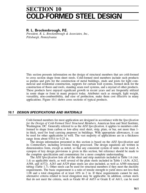
SECTION10COLD-FORMED STEEL DESIGNR.L.Brockenbrough,P.E.President,R.L.Brockenbrough&Associates,Inc.,Pittsburgh,PennsylvaniaThis section presents information on the design of structural members that are cold-formedto cross section shape from sheet steels.Cold-formed steel members include such productsas purlins and girts for the construction of metal buildings,studs and joists for light com-mercial and residential construction,supports for curtain wall systems,formed deck for theconstruction offloors and roofs,standing seam roof systems,and a myriad of other products.These products have enjoyed significant growth in recent years and are frequently utilizedin some shape or form in many projects today.Attributes such as strength,light weight,versatility,non-combustibility,and ease of production,make them cost effective in manyapplications.Figure10.1shows cross sections of typical products.10.1DESIGN SPECIFICATIONS AND MATERIALSCold-formed members for most application are designed in accordance with the Specificationfor the Design of Cold-Formed Steel Structural Members,American Iron and Steel Institute,Washington,DC.Generally referred to as the AISI Specification,it applies to members cold-formed to shape from carbon or low-alloy steel sheet,strip,plate,or bar,not more than1-in thick,used for load carrying purposes in buildings.With appropriate allowances,it canbe used for other applications as well.The vast majority of applications are in a thicknessrange from about0.014to0.25in.The design information presented in this section is based on the AISI Specification and its Commentary,including revisions being processed.The design equations are written indimensionless form,except as noted,so that any consistent system of units can be used.Asynopsis of key design provisions is given in this section,but reference should be made tothe complete specification and commentary for a more complete understanding.The AISI Specification lists all of the sheet and strip materials included in Table1.6(Art.1.4)as applicable steels,as well several of the plate steels included in Table1(A36,A242,A588,and A572).A283and A529plate steels are also included,as well as A500structuraltubing(Table1.7).Other steels can be used for structural members if they meet the ductilityrequirements.The basic requirement is a ratio of tensile strength to yield stress not less than1.08and a total elongation of at least10%in2in.If these requirements cannot be met,alternative criteria related to local elongation may be applicable.In addition,certain steelsthat do not meet the criteria,such as Grade80of A653or Grade E of A611,can be used10.110.2SECTION TENFIGURE10.1Typical cold-formed steel members.for multiple-web configurations(roofing,siding,decking,etc.)provided the yield stress istaken as75%of the specified minimum(or60ksi or414MPa,if less)and the tensile stressis taken as75%of the specified minimum(or62ksi or428MPa if less).Some exceptionsapply.Suitability can also be established by structural tests.10.2MANUFACTURING METHODS AND EFFECTSAs the name suggests,the cross section of a cold-formed member is achieved by a bendingoperation at room temperature,rather than the hot rolling process used for the heavier struc-tural steel shapes.The dominant cold forming process is known as roll-forming.In thisprocess,a coil of steel is fed through a series of rolls,each of which bends the sheetprogressively until thefinal shape is reached at the last roll stand.The number of roll standsmay vary from6to20,depending upon the complexity of the shape.Because the steel isfed in coil form,with successive coils weld-spliced as needed,the process can achieve speedsup to about300ft/min and is well suited for quantity production.Small quantities may beproduced on a press-brake,particularly if the shape is simple,such as an angle or channelcross section.In its simplest form,a press brake consists of a male die which presses thesteel sheet into a matching female die.In general,the cold-forming operation is beneficial in that it increases the yield strength of the material in the region of the bend.Theflat material between bends may also showan increase due to squeezing or stretching during roll forming.This increase in strength isattributable to cold working and strain aging effects as discussed in Art.1.10.The strengthincrease,which may be small for sections with few bends,can be conservatively neglected.Alternatively,subject to certain limitations,the AISI Specification includes provisions forusing a section-average design yield stress that includes the strength increase from cold-forming.Either full section tension tests,full section stub column tests,or an analyticalmethod can be employed.Important parameters include the tensile-strength-to-yield-stressCOLD-FORMED STEEL DESIGN10.3 TABLE10.1Safety Factors and Resistance Factors Adopted by the AISI SpecificationCategoryASDsafetyfactor,⍀LRFDresistancefactor,Tension members 1.670.95 Flexural members(a)Bending strengthSections with stiffened or partially stiffened compressionflanges 1.670.95 Sections with unstiffened compressionflanges 1.670.90 Laterally unbraced beams 1.670.90 Beams having oneflange through-fastened to deck or sheathing(C-or Z-sections) 1.670.90 Beams having oneflange fastened to a standing seam roof system 1.670.90 (b)Web designShear strength controlled by yielding(Condition a,Art.10.12.4) 1.50 1.00 Shear strength controlled by buckling(Condition b or c,Art.10.12.4) 1.670.90 Web crippling of single unreinforced webs 1.850.75 Web crippling of I-sections 2.000.80 Web crippling of two nested Z-sections 1.800.85 Stiffeners(a)Transverse stiffeners 2.000.85(b)Shear stiffeners 1.50/1.67 1.00/0.90 Concentrically loaded compression members 1.800.85 Combined axial load and bending(a)Tension component 1.670.95(b)Compression component 1.800.85(c)Bending component 1.670.90/0.95 Cylindrical tubular members(a)Bending 1.670.95(b)Axial compression 1.800.85 Wall studs(a)Compression 1.800.85(b)Bending 1.670.90/0.95 Diaphragm construction 2.00/3.000.50/0.65 Welded connections(a)Groove weldsTension or compression2500.90 Shear,welds 2.500.80 Shear,base metal 2.500.90 (b)Arc spot weldsShear,welds 2.500.60 Shear,connected part 2.500.50/0.60 Shear,minimum edge distance 2.500.60/0.70 Tension 2.500.60 (c)Arc seam weldsShear,welds 2.500.60 Shear,connected part 2.500.60 (d)Fillet weldsWelds 2.500.60 Connected part,longitudinal loadingWeld length/sheet thicknessϽ25 2.500.60 Weld length/sheet thicknessՆ25 2.500.55 Connected part,transverse loading 2.500.6010.4SECTION TENTABLE10.1Safety Factors and Resistance Factors Adopted by the AISI Specification(Continued)CategoryASDsafetyfactor,⍀LRFDresistancefactor,(e)Flare groove weldsWelds 2.500.60 Connected part,longitudinal loading 2.500.55 Connected part,transverse loading 2.500.55 (f)Resistance welds 2.500.65 Bolted connections(a)Minimum spacing and edge distance*When Fu /FsyՆ1.08 2.000.70When Fu /FsyϽ1.08 2.220.60(b)Tension strength on net sectionWith washers,double shear connection 2.000.65 With washers,single shear connection 2.220.55 Without washers,double or single shear 2.220.65(c)Bearing strength 2.220.55/0.70(d)Shear strength of bolts 2.400.65(e)Tensile strength of bolts 2.00/2.250.75 Screw connections 3.000.50*Fu is tensile strength and Fsyis yield stress.ratio of the virgin steel and the radius-to-thickness ratio of the bends.The forming operation may also induce residual stresses in the member but these effects are accounted for in the equations for member design.10.3NOMINAL LOADSThe nominal loads for design should be according to the applicable code or specificationunder which the structure is designed or as dictated by the conditions involved.In the absenceof a code or specification,the nominal loads should be those stipulated in the AmericanSociety of Civil Engineers Standard,Minimum Design Loads for Buildings and Other Struc-tures,ASCE7.The following loads are used for the primary load combinations in the AISISpecification:DϭDead load,which consists of the weight of the member itself,the weight of allmaterials of construction incorporated into the building which are supported by the mem-ber,including built-in partitions;and the weight of permanent equipmentEϭEarthquake loadLϭLive loads due to intended use and occupancy,including loads due to movable objectsand movable partitions and loads temporarily supported by the structure during mainte-nance.(L includes any permissible load reductions.If resistance to impact loads is takeninto account in the design,such effects should be included with the live load.)COLD-FORMED STEEL DESIGN 10.5L r ϭRoof live load S ϭSnow loadR r ϭRain load,except for ponding W ϭWind loadThe effects of other loads such as those due to ponding should be considered when signif-icant.Also,unless a roof surface is provided with sufficient slope toward points of free drainage or adequate individual drains to prevent the accumulation of rainwater,the roof system should be investigated to assure stability under ponding conditions.10.4DESIGN METHODSThe AISI Specification is structured such that nominal strength equations are given for various types of structural members such as beams and columns.For allowable stress design (ASD),the nominal strength is divided by a safety factor and compared to the required strength based on nominal loads.For Load and Resistance Factor Design (LRFD),the nominal strength is multiplied by a resistance factor and compared to the required strength based on factored loads.These procedures and pertinent load combinations to consider are set forth in the specification as follows.10.4.1ASD RequirementsASD Strength Requirements.A design satisfies the requirements of the AISI Specification when the allowable design strength of each structural component equals or exceeds the required strength,determined on the basis of the nominal loads,for all applicable load combinations.This is expressed asR ՅR /⍀(10.1)n where R ϭrequired strengthR n ϭnominal strength (specified in Chapters B through E of the Specification )⍀ϭsafety factor (see Table 10.1)R n /⍀ϭallowable design strength ASD Load Combinations.In the absence of an applicable code or specification or if the applicable code or specification does not include ASD load combinations,the structure and its components should be designed so that allowable design strengths equal or exceed the effects of the nominal loads for each of the following load combinations:1.D2.D ϩL ϩ(L r or S or R r )3.D ϩ(W or E )4.D ϩL ϩ(L r or S or R r )ϩ(W orE )Wind or Earthquake Loads for ASD.When the seismic load model specified by the applicable code or specification is limit state based,the resulting earthquake load (E )is permitted to be multiplied by 0.67.Additionally,when the specified load combinations in-clude wind or earthquake loads,the resulting forces are permitted to be multiplied by 0.75.However,no decrease in forces is permitted when designing diaphragms.10.6SECTION TENComposite Construction under ASD.For the composite construction offloors and roofs using cold-formed deck,the combined effects of the weight of the deck,the weight of thewet concrete,and construction loads(such as equipment,workmen,formwork)must beconsidered.10.4.2LRFD RequirementsLRFD Strength Requirements.A design satisfies the requirements of the AISI Specificationwhen the design strength of each structural component equals or exceeds the requiredstrength determined on the basis of the nominal loads,multiplied by the appropriate loadfactors,for all applicable load combinations.This is expressed asRϽR(10.2)u nwhere Ruϭrequired strengthRnϭnominal strength(specified in chapters B through E of the Specification)ϭresistance factor(see Table10.1)R nϭdesign strengthLRFD Load Factors and Load Combinations.In the absence of an applicable code or specification,or if the applicable code or specification does not include LRFD load combi-nations and load factors,the structure and its components should be designed so that design strengths equal or exceed the effects of the factored nominal loads for each of the following combinations:1.1.4DϩL2.1.2Dϩ1.6Lϩ0.5(Lr or S or Rr)3.1.2Dϩ1.6(Lr or S or Rr)ϩ(0.5L or0.8W)4.1.2Dϩ1.3Wϩ0.5Lϩ0.5(Lr or S or Rr)5.1.2Dϩ1.5Eϩ0.5Lϩ0.2S6.0.9DϪ(1.3W or1.5E)Several exceptions apply:1.The load factor for E in combinations(5)and(6)should equal1.0when the seismic loadmodel specified by the applicable code or specification is limit state based.2.The load factor for L in combinations(3),(4),and(5)should equal1.0for garages,areasoccupied as places of public assembly,and all areas where the live load is greater than 100psf.3.For wind load on individual purlins,girts,wall panels and roof decks,multiply the loadfactor for W by0.9.4.The load factor for Lr in combination(3)should equal1.4in lieu of1.6when the rooflive load is due to the presence of workmen and materials during repair operations.Composite Construction under LRFD.For the composite construction offloors and roofs using cold-formed deck,the following additional load combination applies:1.2Dϩ1.6Cϩ1.4C(10.3)S Wwhere DSϭweight of steel deckCWϭweight of wet concreteCϭconstruction load(including equipment,workmen,and form work but excluding wet concreteCOLD-FORMED STEEL DESIGN10.7 10.5SECTION PROPERTY CALCULATIONSBecause of theflexibility of the manufacturing method and the variety of shapes that can bemanufactured,properties of cold-formed sections often must be calculated for a particularconfiguration of interest rather than relying on tables of standard values.However,propertiesof representative or typical sections are listed in the Cold-Formed Steel Design Manual,American Iron and Steel Institute,1996,Washington,DC(AISI Manual).Because the cross section of a cold-formed section is generally of a single thickness of steel,computation of section properties may be simplified by using the linear method.Withthis method,the material is considered concentrated along the centerline of the steel sheetand area elements are replaced by straight or curved line elements.Section properties arecalculated for the assembly of line elements and then multiplied by the thickness,t.Thus,the cross section area is given by AϭLϫt,where L is the total length of all line elements;the moment of inertia of the section is given by IϭIЈϫt,where IЈis the moment ofinertia determined for the line elements;and the section modulus is calculated by dividingI by the distance from the neutral axis to the extremefiber,not to the centerline of theextreme element.As subsequently discussed,it is sometimes necessary to use a reduced oreffective width rather than the full width of an element.Most sections can be divided into straight lines and circular arcs.The moments of inertia and centroid location of such elements are defined by equations from fundamental theory aspresented in Table10.2.10.6EFFECTIVE WIDTH CONCEPTThe design of cold-formed steel differs from heavier construction in that elements of mem-bers typically have large width-to-thickness(w/t)ratios and are thus subject to local buck-ling.Figure10.2illustrates local buckling in beams and columns.Flat elements in com-pression that have both edges parallel to the direction of stress stiffened by a web,flange,lip or stiffener are referred to as stiffened elements.Examples in Fig.10.2include the topflange of the channel and theflanges of the I-cross section column.To account for the effect of local buckling in design,the concept of effective width is employed for elements in compression.The background for this concept can be explainedas follows.Unlike a column,a plate does not usually attain its maximum load carrying capacity at the buckling load,but usually shows significant post buckling strength.This behavior isillustrated in Fig.10.3,where longitudinal and transverse bars represent a plate that is simplysupported along all edges.As the uniformly distributed end load is gradually increased,thelongitudinal bars are equally stressed and reach their buckling load simultaneously.However,as the longitudinal bars buckle,the transverse bars develop tension in restraining the lateraldeflection of the longitudinal bars.Thus,the longitudinal bars do not collapse when theyreach their buckling load but are able to carry additional load because of the transverserestraint.The longitudinal bars nearest the center can deflect more than the bars near theedge,and therefore,the edge bars carry higher loads after buckling than do the center bars.The post buckling behavior of a simply supported plate is similar to that of the grid model.However,the ability of a plate to resist shear strains that develop during bucklingalso contributes to its post buckling strength.Although the grid shown in Fig.10.3a buckledinto only one longitudinal half-wave,a longer plate may buckle into several waves as illus-trated in Figs.10.2and10.3b.For long plates,the half-wave length approaches the widthb.After a simply supported plate buckles,the compressive stress will vary from a maximum near the supported edges to a minimum at the mid-width of the plate as shown by line1of10.8SECTION TENTABLE10.2Moment of Inertia for Line ElementsSource:Adapted from Cold-Formed Steel Design Manual,American Iron and Steel Institute,1996,Washington,DC.COLD-FORMED STEEL DESIGN10.9FIGURE10.2Local buckling of compression elements.(a)In beams;(b)incolumns.(Source:Commentary on the Specification for the Design of Cold-Formed Steel Structural Members,American Iron and Steel Institute,Washington,DC,1996,with permission.)Fig.10.3c.As the load is increased the edge stresses will increase,but the stress in the mid-width of the plate may decrease slightly.The maximum load is reached and collapse is initiated when the edge stress reaches the yield stress—a condition indicated by line2of Fig.10.3c.The post buckling strength of a plate element can be considered by assuming that after buckling,the total load is carried by strips adjacent to the supported edges which are at a uniform stress equal to the actual maximum edge stress.These strips are indicated by the dashed lines in Fig.10.3c.The total width of the strips,which represents the effective width of the element b,is defined so that the product of b and the maximum edge stress equals the actual stresses integrated over the entire width.The effective width decreases as the applied stress increases.At maximum load,the stress on the effective width is the yield stress.Thus,an element with a small enough w/t will be able to reach the yield point and will be fully effective.Elements with larger ratios will have an effective width that is less than the full width,and that reduced width will be used in section property calculations.The behavior of elements with other edge-support conditions is generally similar to that discussed above.However,an element supported along only one edge will develop only one effective strip.Equations for calculating effective widths of elements are given in subsequent articles based on the AISI Specification.These equations are based on theoretical elastic buckling theory but modified to reflect the results of extensive physical testing.10.10SECTION TENFIGURE10.3Effective width concept.(a)Buckling of grid model;(b)buckling ofplate;(c)stress distributions.10.7MAXIMUM WIDTH-TO-THICKNESS RATIOSThe AISI Specification gives certain maximum width-to-thickness ratios that must be adhered to.For flange elements,such as in flexural members or columns,the maximum flat width-to-thickness ratio,w/t ,disregarding any intermediate stiffeners,is as follows:Stiffened compression element having one longitudinal edge connected to a web or flange element,the other stiffened by (a)a simple lip,60(b)other stiffener with I S ϽI a ,90(c)other stiffener with I S ՆI a ,90Stiffened compression element with both longitudinal edges connected to other stiffened elements,500Unstiffened compression element,60In the above,I S is the moment of inertia of the stiffener about its centroidal axis,parallel to the element to be stiffened,and I a is the moment of inertia of a stiffener adequate for the element to behave as a stiffened element.Note that,although greater ratios are permitted,stiffened compression elements with w /t Ͼ250,and unstiffened compression elements with w/t Ͼ30are likely to develop noticeable deformations at full design strength,but ability to develop required strength will be unaffected.For web elements of flexural members,the maximum web depth-to-thickness ratio,h/t ,disregarding any intermediate stiffeners,is as follows:Unreinforced webs,200Webs with qualified transverse stiffeners that include (a)bearing stiffeners only,260(b)bearing and intermediate stiffeners,30010.8EFFECTIVE WIDTHS OF STIFFENED ELEMENTS10.8.1Uniformly Compressed Stiffened ElementsThe effective width for load capacity determination depends on a slenderness factor defined as1.052wƒϭ(10.4)ͩͪΊt E͙kwhere k ϭplate buckling coefficient (4.0for stiffened elements supported by a web alongeach longitudinal edge;values for other conditions are given subsequently)ƒϭmaximum compressive stress (with no safety factor applied)E ϭModulus of elasticity (29,500ksi or 203000MPa)FIGURE 10.4Illustration of uniformly compressed stiffened element.(a )Actual element;(b )stress on effective element.(Source:Specification for the Design of Cold-Formed Steel Structural Members,Amer-ican Iron and Steel Institute,Washington,DC,1996,with permission.)For flexural members,when initial yielding is in compression,ƒϭF y ,where F y is the yield stress;when the initial yielding is in tension,ƒϭthe compressive stress determined on the basis of effective section.For compression members,ƒϭcolumn buckling stress.The effective width is as follows:when Յ0.673,b ϭw (10.5)when Ͼ0.673,b ϭw(10.6)where the reduction factor is defined asϭ(1Ϫ0.22/)/(10.7)Figure 10.4shows the location of the effective width on the cross section,with one-half located adjacent to each edge.Effective widths determined in this manner,based on maximum stresses (no safety factor)define the cross section used to calculate section properties for strength determination.How-ever,at service load levels,the effective widths will be greater because the stresses are smaller,and another set of section properties should be calculated.Therefore,to calculate effective width for deflection determination,use the above equations but in Eq.10.4,sub-stitute the compressive stress at design loads,ƒd .10.8.2Stiffened Elements with Stress GradientElements with stress gradients include webs subjected to compression from bending alone or from a combination of bending and uniform compression.For load capacity determination,the effective widths b 1and b 2illustrated in Fig.10.5must be determined.First,calculate the ratio of stressesϭƒ/ƒ(10.8)21where ƒ1and ƒ2are the stresses as shown,calculated on the basis of effective section,with no safety factor applied.In this case ƒ1is compression and treated as ϩ,while ƒ2can be either tension (Ϫ)or compression (ϩ).Next,calculate the effective width,b e ,as if the element was in uniform compression (Art.10.8.1)using ƒ1for ƒand with k determined as follows:3k ϭ4ϩ2(1Ϫ)ϩ2(1Ϫ)(10.9)Effective widths b 1and b 2are determined from the following equations:FIGURE10.5Illustration of stiffened element with stress gradient.(a)Actual element;(b)stress on ef-fective element varying from compression to tension;(c)stress on effective element with non-uniform com-pression.(Source:Specification for the Design of Cold-Formed Steel Structural Members,American Iron and Steel Institute,Washington,DC,1996,with permission.)bϭb/(3Ϫ)(10.10)1ebϭb/2(10.11)2eThe sum of b1and b2must not exceed the width of the compression portion of the webcalculated on the basis of effective section.Effective width for deflection determination is calculated in the same manner except that stresses are calculated at service load levels based on the effective section at that load.FIGURE 10.6Illustration of uniformly compressed unstiffened element.(a )Actual element;(b )stress on effective element.(Source:Specification for the Design of Cold-Formed Steel Structural Members,American Iron and Steel Institute,Washington,DC,1996,with permission.)10.9EFFECTIVE WIDTHS OF UNSTIFFENED ELEMENTS10.9.1Uniformly Compressed Unstiffened ElementsThe effective widths for uniformly compressed unstiffened elements are calculated in the same manner as for stiffened elements (Art.10.8.1),except that k in Eq.10.4is taken as 0.43.Figure 10.6illustrates the location of the effective width on the cross section.10.9.2Unstiffened Elements and Edge Stiffeners with Stress GradientThe effective width for unstiffened elements (including edge stiffeners)with a stress gradient is calculated in the same manner as for uniformly loaded stiffened elements (Art.10.9.1)except that (1)k in Eq.10.4is taken as 0.43,and (2)the stress ƒ3is taken as the maximum compressive stress in the element.Figure 10.7shows the location of ƒ3and the effective width for an edge stiffener consisting of an inclined lip.(Such lips are more structurally efficient when bent at 90Њ,but inclined lips allow nesting of certain sections.)10.10EFFECTIVE WIDTHS OF UNIFORMLY COMPRESSED ELEMENTS WITH EDGE STIFFENERA commonly encountered condition is a flange with one edge stiffened by a web,the other by an edge stiffener (Fig.10.7).To determine its effective width for load capacity determi-nation,one of three cases must be considered.The case selection depends on the relation between the flange flat width-to-thickness ratio,w/t ,and the parameter S defined asS ϭ1.28͙E /ƒ(10.12)For each case an equation will be given for determining I a ,the moment of inertia required for a stiffener adequate so that the flange element behaves as a stiffened element,I S is the moment of inertia of the full section of the stiffener about its centroidal axis,parallel to the element to be stiffened.A ЈS is the effective area of a stiffener of any shape,calculated by methods previously discussed.The reduced area of the stiffener to be used in section property calculations is termed A S and its relation to A ЈS is given for each case.Note that for edge stiffeners,the rounded corner between the stiffener and the flange is not considered as part of the stiffener in calculations.The following additional definitions for a simple lip stiffener illustrated in Fig.10.7apply.The effective width d S Јis that of the stiffener calculated ac-cording to Arts.10.9.1and 10.9.2.The reduced effective width to be used in section propertyFIGURE 10.7Illustration of element with edge stiffener.(a )Actual element;(b )stress on effective element and stiffener.(Source:Specification for the Design of Cold-Formed Steel Structural Members,American Iron and Steel Institute,Washington,DC 1996,with permission.)calculations is termed d S and its relation to d S Јis given for each case.For the inclined stiffener of flat depth d at an angle as shown in Fig.10.7,32I ϭ(d t sin )/12(10.13)S A Јϭd Јt(10.14)S S Limit d /t to 14.Case I:w /t ՅS /3For this condition,the flange element is fully effective without an edge stiffener so b ϭw ,I a ϭ0,d S ϭd S Ј,A S ϭA ЈS .Case II:S /3Ͻw /t ϽS43I ϭ399t {[(w /t )/S ]Ϫ͙k /4}(10.15)a u where k u ϭ0.43.The effective width b is calculated according to Art.10.8.1using the following k :。
美国冷弯薄壁型钢规范(图)

简介美国冷弯薄壁型钢规范全面升级在美国钢框架联盟(Steel Framing Alliance)网站下单2个多月后,今天公司终于收到了刚刚升级完成的全套北美冷弯薄壁型钢结构设计规范((North American Standard for Cold-formed Steel Framing 2007Edition).之前据说这次升级幅度很大,反映了最近几年北美冷弯薄壁型钢结构界的最新研究成果,下班回家后大致翻了一下,果然动作很大。
先简要摘录如下:一是有更新又有新增;这是再原有基础上更新的标准:•AISI S200-07: North American Standard for Cold-Formed Steel Framing – General Provisions •AISI S211-07: North American Standard for Cold-Formed Steel Framing – Wall Stud Design •AISI S212-07: North American Standard for Cold-Formed Steel Framing – Header Design •AISI S213-07: North American Standard for Cold-Formed Steel Framing – Lateral Design •AISI S214-07: North American Standard for Cold-Formed Steel Framing – Truss Design •AISI S230-07: Standard for Cold-Formed Steel Framing –Prescriptive Method for One and Two Family Dwellings以下是这次新增的标准:•AISI S201-07: North American Standard for Cold-Formed Steel Framing – Product Data •AISI S210-07: North American Standard for Cold-Formed Steel Framing – Floor and Roof System Design二是这次将加拿大和墨西哥规范一起统一了起来,真正形成了北美标准;三是内容进行了很大的更新,特别是Lateral Design分册,有了很大的扩充;四是发现North American Specification and Commentary fo the Design of Cold-Formed Steel Structural Members 2007 Edition先于North American Standard for Cold-Formed Steel Framing 标准发布了。
美国钢结构规范中文版

美国钢结构规范中文版美国钢结构规范是指工程设计和施工过程中使用的一套标准和规范,用于确保钢结构的安全性和可靠性。
这些规范涵盖了许多方面,包括钢材的选材、结构设计、连接方式、施工质量控制等。
下面是美国钢结构规范中文版的简要介绍。
首先,美国钢结构规范中定义了各类钢材的强度等级以及机械性能要求。
该规范还详细阐述了钢材的焊接、铆接和螺栓连接等方面的设计和施工要求,确保连接的稳定和可靠。
其次,钢结构设计方面,该规范规定了各类结构的荷载计算方法和设计标准。
例如,该规范中包括了不同类型的荷载,如静载、动载、地震荷载等。
对于每个类型的荷载,规范规定了相应的计算方法和安全系数,以确保钢结构的稳定性。
此外,美国钢结构规范还包含了一些具体的设计和施工要求。
例如,在进行框架结构设计时,规范规定了框架的几何尺寸、截面形状和支撑方式等要求。
对于底座和基础的设计,规范也给出了详细的要求,包括基础尺寸、材质和强度等。
规范还详细阐述了钢结构的施工质量控制要求。
例如,规范规定了焊接和铆接接头的检验方法和标准。
每一处焊接或铆接接头都需要进行非破坏性检测,以确保其质量达到规定的要求。
在使用过程中,该规范还规定了钢结构的维护和保养要求,以确保其服务寿命和安全性。
规范给出了钢结构维护周期、维护方法、检查项目等具体要求。
最后,美国钢结构规范中还包含了一些强制性的测试和验收标准。
例如,在钢结构竣工后,工程质量验收需要进行材料检测、接头检验、连接强度测试等。
只有通过这些测试,钢结构才能正式投入使用。
总之,美国钢结构规范是确保钢结构工程质量和安全性的一套标准和规范。
其涵盖了钢材选材、结构设计、连接方式、施工质量控制等方面。
遵循该规范可以保证钢结构工程的可靠性和稳定性,在建筑和工程设计领域具有重要的指导意义。
美国钢结构建筑设计规范(ANSI-AISC-360-05)

关于钢结构建筑设计规范的条文说明(本条文说明不是《钢结构建筑设计规范》(ANSI/AISC 360-05)的一部分,而只是为该规范使用人员提供相关信息。
)序言本设计规范旨在提供完善的标准设计之用。
本条文说明是为该规范使用人员提供规范条文的编制背景、文献出处等信息帮助,以进一步加深使用人员对规范条文的基础来源、公式推导和使用限制的了解。
本设计规范和条文说明旨在供具有杰出工程能力的专业设计员使用。
术语表本条文说明使用的下列术语不包含在设计规范的词汇表中。
在本条文说明文本中首次出现的术语使用了斜体。
准线图。
用于决定某些柱体计算长度系数K的列线图解。
双轴弯曲。
某一构件在两垂直轴同时弯曲。
脆性断裂。
在没有或是只有轻微柔性变形的情况下突然断裂。
柱体弧线。
表达砥柱强度和直径长度比之间关系的弧线。
临界负荷。
根据理论稳定性分析,一根笔直的构件在压力下可能弯曲,也可能保持笔直状态时的负荷;或者一根梁在压力下可能弯曲,平截面发生扭曲或者其平截面状态时的负荷。
循环负荷。
重复地使用可以让结构体变得脆弱的额外负荷。
位移残损索引。
用于测量由内部位移引起的潜性损坏的参变量。
有效惯性矩。
构件横截面的惯性矩在该横截面发生部分逆性化的情况下(通常是在内应力和外加应力共同作用下),仍然保持其弹性。
同理,基于局部歪曲构件的有效宽度的惯性矩。
同理,用于设计部分组合构件的惯性矩。
有效劲度。
通过构件横截面有效惯性矩计算而得的构件劲度。
疲劳界限。
不计载荷循环次数,不发生疲劳断裂的压力范围。
一阶逆性分析。
基于刚逆性行为假设的结构分析,而未变形结构体的平衡条件便是基于此分析而归纳出来的——换言之,平衡是在结构体和压力等于或是低于屈服应力条件下实现的。
柔性连接。
连接中,允许构件末端简支梁的一部分发生旋转,而非全部。
挠曲。
受压构件同时发生弯曲和扭转而没有横截面变形的弯曲状态。
非弹性作用。
移除促生作用力后,材料变形仍然不消退的现象。
非弹性强度。
当材料充分达到屈服应力时,结构体或是构件所具有的强度。
- 1、下载文档前请自行甄别文档内容的完整性,平台不提供额外的编辑、内容补充、找答案等附加服务。
- 2、"仅部分预览"的文档,不可在线预览部分如存在完整性等问题,可反馈申请退款(可完整预览的文档不适用该条件!)。
- 3、如文档侵犯您的权益,请联系客服反馈,我们会尽快为您处理(人工客服工作时间:9:00-18:30)。
7.13 LRFD FOR COMPOSITE BEAM WITH UNIFORM LOADSThe typical floor construction of a multistory building is to have composite framing. The floor consists of 31⁄4-in-thick lightweight concrete over a 2-in-deep steel deck. The concrete weighs 115 lb/ft3and has a compressive strength of 3.0 ksi. An additional 30% of the dead load is assumed for equipment load during construction. The deck is to be supported onsteel beams with stud shear connectors on the top flange for composite action (Art. 7.12).Unshored construction is assumed. Therefore, the beams must be capable of carrying their own weight, the weight of the concrete before it hardens, deck weight, and construction loads. Shear connectors will be3⁄4 in in diameter and 31⁄2 in long. The floor system should be investigated for vibration, assuming a damping ratio of 5%.FIGURE 7.6 Seven locations of the plastic neutral axis used for determining the strength of a composite beam.(a) For cases 6 and 7, the PNA lies in the web. (b) For cases 1 through 5, the PNA lies in the steel flange.A typical beam supporting the deck is 30 ft long. The distance to adjacent beams is 10 ft. Ribs of the deck are perpendicular to the beam. Uniform dead loads on the beam are construction, 0.50 kips per ft, plus 30% for equipment loads, and superimposed load, 0.25 kips per ft. Uniform live load is 0.50 kipsper ft.Q for Partial Composite Design(kips)TABLE 7.3nLocation of PNA n Q and concrete compression(1)y x F A (2)to (5)*2y f y s F A F A ∆- (6) 0.5[C(5)+C(7)] †(7)0.25y s F A* A ƒ area of the segment of the steel flange above the plastic neutral axis (PNA). †C (n ) compressive force at location (n ). Beam Selection. Initially, a beam of A36 steel that can support the construction loads is selected. It is assumed to weigh 26 lb /ft. Thus the beam is to be designed for a service dead load of 0.5×1.3+0.026=0.676 kips per ft.Factored load=0.676*1.4=0.946 kips per ftFactored moment = u M =0.946×302/8=106.5 kip-ftThe plastic section modulus required therefore isZ=369.0125.106⨯⨯=y u F M φ=39.43in Use a W16 ×26 (Z =44.2 3in and moment of inertia I =301 4in ).The beam should be cambered to offset the deflection due to a dead load of 0.50 +0.026 =0.526 kips per ft.Camber =1.1301000,293841230526.0534=⨯⨯⨯⨯⨯in Camber can be specified on the drawings as 1 in.Strength of Fully Composite Section.Next, the composite steel section is designed to support the total loads. The live load may be reduced in accordance with area supported (Art. 7.9). The reduction factor is R = 0.0008(300-150) =0.12. Hence the reduced live load is 0.5(1 - 0.12) = 0.44 kips per ft. The factored load is the larger of the following:1.2(0.50 + 0.25 + 0.026) × 1.6 +0.44= 1.635 kips per ft1.4(0.5 + 0.25 + 0.026) =1.086 kips per ftHence the factored moment is9.1838/30635.12=⨯=u M kip-ftThe concrete-flange width is the smaller of b = 10 ×12 = 120 in or b = 2(30 ×12⁄8) =90 in (governs).The compressive force in the concrete C is the smaller of the values computed from Eqs. (7.24) and (7.25).=⨯⨯⨯==25.390385.085.0'c c c A f C 745.9kips==y s t F A C 7.68×36=276.5 kips (governs)The depth of the concrete compressive-stress block (Fig. 7.5) isa==⨯⨯=900.385.02760585.0'b f C c 1.205in Since t c C C >,the plastic neutral axis will line in the concrete slab (case 3, Art.7.12). The distance between the compression and tension forces on the W16 ×26 (Fig.7.5d) ise =0.5d + 5.25 - 0.5a= 0.5 × 15.69 + 5.25- 0.5 ×1.205 =12.493 inThe design strength of the W16 × 26 is==e C M t n 85.0φ0.85×276.5×12.493/12=244.7 kip-ft >183.9 kip-ft —OKPartial Composite Design. Since the capacity of the full composite section is more than required, a partial composite section may be satisfactory. Seven values of the composite section (Fig. 7.6) are calculated as follows, with the flange area f A = 5.5 ×0.345 = 1.8982in .1.Full composite:y s n F A Q =∑= 276.5 kips=n M φ 276.5 kips2.Plastic neutral axis f f A A =∆/4 = 0.4745 in below the top of the top flange. From Table7.3,y f y s n F A F A Q ∆-=∑2∑n Q =276.5 -2 × 0.4745 ×36 = 242.3a =242.3/(0.85 × 3.0 × 90) = 1.0558 ine = 15.69/2 × 5.25 - 1.0558/2 = 12.567 inn M =242.3 × 12.567 +0.5(276.5-242.3)×(15.69 - 0.34536898.123.2425.276⨯⨯-)= 3,312 kip-in =n M φ 0.85 × 3312/12 ? 234.6 kip-ft3.PNA 2/f A Af =∆=0.949 in below the top of the top flange:=∑n Q 208.2 kips=n M φ 224.0 kip-ft4. PN f f A A 3=∆/4 =1.4235 in below the top of the top flange:=∑n Q 174.0 kips=n M φ 212.8 kip-ft5. PNA at the bottom of the top flange (f f A A =∆):=∑n Q 139.9 kips=n M φ201.0 kip-ft6. Plastic neutral axis within the web.∑n Q is the average of items 5 and 7. (See Table 7.3.) =∑n Q (139.9 ? 69.1)/2 ? 104.5 kips=n M φ186.4 kip-ft7. =∑n Q 0.25 ? 276.5 ? 69.1 kips=n M φ166.7 kip-ftFrom the partial composite values 2 to 7, value 6 is just greater than =u M 183.9 kip-ft. The AISC ‘‘Manual of Steel Construction ’’ includes design tables for composite beams that greatly simplify the calculations. For example, the table for the W16 × 26, grade 36, composite beam gives n M φfor the seven positions of the PNA and for several values of the distance 2Y (in) from the concrete compressive force C to the top of the steel beam. For the preceding example,con Y Y =2-a/2 (7.31)where con Y = total thickness of floor slab, ina=depth of the concrete compressive-stress block, inFrom the table for case 6,∑n Q =104 kips. a=900.385.0104⨯⨯=0.453 in Substitution of a and =con Y 5.25 in in Eq. (7.31) gives=2Y 5.25-0.453/2 =5.02 inThe manual table gives the corresponding moment capacity for case 6 and =2Y 5.02 in as =n M φ186 kip-ft > 183.9 kip-ft —OKThe number of shear studs is based on C=104.5 kips. The nominal strength n Q of one stud is given by Eq. (7.28). For a 3⁄4-in stud, with shearing area sc A = 0.442 2in and tensile strength u F =60 ksi, the limiting strength is u sc F A = 0.442× 60 = 26.5 kips. With concrete unit weight w=115 lb/3ft and compressive strength 'c f =3.0 ksi, and modulus of elasticity c E = 2136 ksi, the nominal strength given by Eq. (7.28) isn Q =0.5 ×0.442 21360.3⨯= 17.7 kips < 26.5 kipsThe number of shear studs required is 2 × 104.5/17.7 =11.8. Use 12. The total number of metal deck ribs supported on the steel beam is 30. Therefore, only one row of shear studs is required, and no reduction factor is needed.Deflection Calculations. Deflections are calculated based on the partial composite properties of the beam. First, the properties of the transformed full composite section (Fig. 7.7) are determined. The modular ratio n s E E is n = 29,000/2136 = 13.6. This is used to determine the transformed concrete area 1A = 3.25 × 90/13.6 = 21.52 in2. The area of the W16 × 26 is 7.68 2in , and its moment of inertia s I = 301 4in . The location of the elastic neutral axis is determined by taking moments of the transformed concrete area and the steel area about the top of the concrete slab: X=68.752.21)25.569.155.0(68.72/25.352.21++⨯+⨯=4.64 in The elastic transformed moment of inertia for full composite action is1065301)64.425.5269.15(68.7)225.364.4(52.21126.1325.390223=+-++-+⨯⨯=tr I 4in Since partial composite construction is used, the effective moment of inertia is determined from 47.7705.276/5.104)3011065(301in I eff =-+=eff I is used to calculate the immediate deflection under service loads (without long-term effects). For long-term effect on deflections due to creep of the concrete, the moment of inertia is reduced to correspond to a 50% reduction in c E . Accordingly, the transformed moment of inertia with full composite action and 50% reduction in c E is tr I = 900.34in and is based on a modular ratio 2n =27.2. The corresponding transformed concrete area is 1A =10.76 2in .FIGURE 7.7 Transformed section of a composite beam.The reduced effective moment of inertia for partial composite construction with long- term effect is determined from Eq. (7.32):。