ANSYS modeling
ANSYS建模
轴承座的ANSYS实体建模:实验报告(一)一、实验目的:进一步练习ANSYS软件的操作;学会建立模型的高级操作和步骤;实际操作建立微微机械车轮模型。
(一)基本思路有限元分析的最终目的是还原一个实际工程系统的数学行为特征,即分析必须针对一个物理原型准确的数学模型。
广义上讲,模型包括所有节点、单元、材料属性、实常数、边界条件,以及其他用来表现这个物理系统的特征。
建立模型的典型步骤是:(1)确定分析目标及模型的基本形式,选择合适的单元类型并考虑如何建立适当的网格密度。
(2)进入前处理(PREP7)建立模型,一般情况下利用实体建模创建模型。
(3)建立工作平面。
(4)利用几何元素和布尔运算操作生成基本几何形状。
(5)激活适当的坐标系。
(6)用自底向上方法生成其他实体,即定义关键点后生成线、面和体。
(7) 用布尔运算或编号控制适当地连接各个独立的实体模型域。
四、实验内容及步骤 (一)轴承座建模 1. 创建基座模型(1)、生成基座部分的长方体: 单击Main MenuPreprocessCreateVolumesBlockByDimensions ,输入X1=0,X2=3,Y1=0,Y2=1,Z1=0,Z2=3,然后单击[OK],得长方体基座。
XY Z09060242-44-sunguoliang(2)、平移并旋转工作平面:Utility Menu WorkPlane OffsetWP by IncrementsX,Y,Z Offsets 输入 2.25,1.25,0.75,点击[Apply],XY ,YZ ,ZX Angles 输入0,-90,0,单击[OK]。
(3)、创建圆柱体: 单击Main Menu PreprocessorModelingCreateVolumesCylinderSolid Cylinder,输入 WP X=0,WP Y=0,Radius=0.75/2, Depth=-1.5,单击[OK]。
在ansys中如何对实体进行抽壳
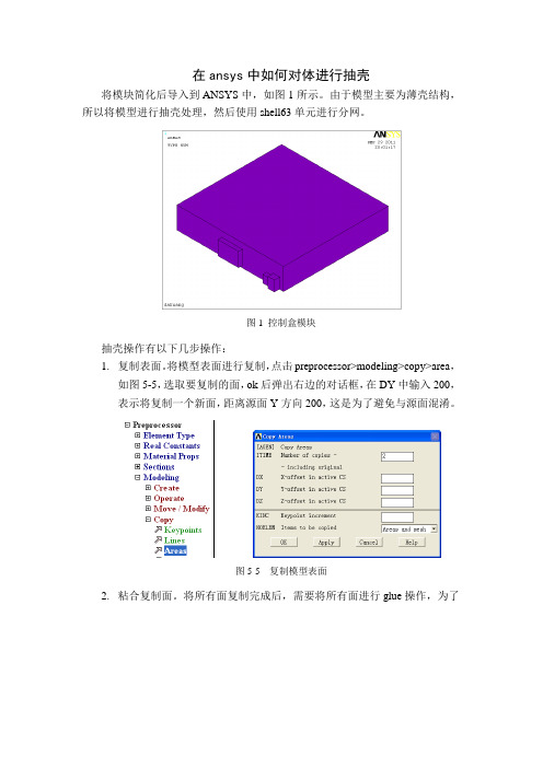
在ansys中如何对体进行抽壳将模块简化后导入到ANSYS中,如图1所示。
由于模型主要为薄壳结构,所以将模型进行抽壳处理,然后使用shell63单元进行分网。
图1 控制盒模块抽壳操作有以下几步操作:1.复制表面。
将模型表面进行复制,点击preprocessor>modeling>copy>area,如图5-5,选取要复制的面,ok后弹出右边的对话框,在DY中输入200,表示将复制一个新面,距离源面Y方向200,这是为了避免与源面混淆。
图5-5 复制模型表面2.粘合复制面。
将所有面复制完成后,需要将所有面进行glue操作,为了图5-6 glue操作是使新复制的面保持连续性,点击preprocessor>modeling>operate>Booleans> glue>area,如图5-6,选取所有复制面后确定。
3.删除源体。
复制完成后,之前的源体需要进行删除,点击preprocessor>modeling>delete>volume and below,如图5-7,选取要删除的体后确定。
图5-7 删除体4.修改复制面位置。
体删除后,需要将复制的面改为原来的位置,点击图5-8 修改复制面位置preprocessor>modeling>move/modify>area>area,如图5-8,选取全部复制的面,在弹出的对话框DY输入-200。
复制后的面之前都属于同一体,删除体后变得零散,需要再次将它们结合起来,借助ANSYS中的组件功能来实现。
点击select>comp/assembly>create图5-9 创建组件Component,如图5-9,弹出对话框,在cname中输入自定义命名ak,注意必须以英文字母为首,在entity中选择area,点击ok。
之后输入Cmsel,s,ak,area就可以直接找到这些复制面。
Ansys 14.0 Workbench 课件6-DM-Intro_Modeling
拉伸
拉伸
• Geometry
– 可以是草图,选定的面或命名选择
• Operation
– 可进行 Add Material, Cut Material, Imprint Faces, Slice Material, Add frozen等操作 – 后面会详细介绍
• Direction Vector
– 对草图进行拉伸时,拉伸方向默认为法向,否 则需要用户指定。 – 平面轴线,几何的边和面都可以用来指定方向。
蒙皮/放样
蒙皮/放样
• 通过一系列几何轮廓创建体
– 所有的几何轮廓边数要相等
多个草图
20
© 2011 ANSYS, Inc.
March 10, 2014
Release 14.0
抽壳
抽壳
• Selection Type Faces to Keep/Faces to
Remove
– 保留选定的面,移除未选定的面,创建一个 具有指定厚度的体 – 指定厚度为零将生成一个面(壳指定偏置) – Bodies Only 选项可以创建薄壁实体或者对 面进行平移 – 产生厚度的方向可以是向内,向外或向两侧
March 10, 2014
Release 14.0
体操作:缩放
• 对选定的体进行缩放 • 选定一个或多个体 • 设置Scaling origin
– World Origin : 全局坐标原点 – Body Centroids: 所选定的体的圆心 – Point: 选定的点
Scale up : 2x
• 实例:拉伸形成的两个激活体, 如果几何上相邻,
就会合并为一个体。 • 如何将体定义为激活状态?
– 在创建体之前-----选择 ‘Add Material’
有限元软件ANSYS主要菜单中文解释
有限元软件ANSYS主要菜单中文解释ANSYS9.0程序主要菜单中文解释(1) 实用菜单窗口【Utility Menu】实用菜单中的子菜单都是下拉菜单,包括有:【File】文件管理菜单【Select】选择菜单【List】显示菜单【Plot】绘图菜单【PlotCtrls】绘图控制菜单【WorkPlane】工作平面菜单【Parameters】参数控制菜单【Macro】宏管理菜单【MenuCtrls】菜单控制菜单【Help】帮助菜单a. 文件管理菜单【File】【Clear & Start New…】清除或重新启动【Change Jobname…】改变作业名【Change Directory…】改变目录【Change Title…】改变题目【Resum Jobname.db…】取回作业【Resum from…】从目录中取回【Save as Jobname.db】储存作业【Save as…】另存作业【Write DB Log file…】输出.db Log文件【Read Input from…】读入文件【Switch Output to ?】输出结果文件【List ?】显示文件内容【File Options ?】对文件进行重命名、删除和复制等操作【ANSYS File Options…】设定ANSYS文件的属性等【Import ?】导入其他CAD系统的文件【Export…】导出IGES格式的文件【Report Generator…】报告生成器【Exet…】退出b. 选择菜单【Select】【Entites…】选择实体【Component Manager…】组元管理【Comp/Assembly ?】选择组元和集合【Everything】重新激活整个模型【Everything Below ?】激活某类实体c.显示菜单【List】【File ?】显示文件内容【Status ?】显示选取内容的状态【Keypoint ?】显示关键点的属性和相关数据【Lines…】显示线的属性和相关数据【Areas】显示面的属性和相关数据【V olumes】显示体的属性和相关数据【Nodes…】显示节点的属性和相关数据【Elements ?】显示单元的属性和相关数据【Components】显示组元的属性和相关数据【Picked Entities +】显示选中的实体属性和相关数据【Properties ?】显示要查询内容的属性【Loads ?】显示载荷【Results ?】显示求解结果【Other ?】显示模型中其他的一些信息d. 绘图菜单【Plot】【Replot】重新绘制图形窗口中模型【Keypoints ?】在图形窗口中只绘制关键点【Lines】在图形窗口中只绘制线【Areas】在图形窗口中只绘制面【V olumns】在图形窗口中只绘制三维实体【Specified Entities ?】在图形窗口中只绘制指定的图元【Nodes】在图形窗口中只绘制节点【Elements】在图形窗口中只绘制单元【Layered Elements…】在图形窗口中只绘制分层的单元【Materials…】在图形窗口中只绘制材料属性【Data Tables…】在图形窗口中只绘制定义过的材料属性【Array paramentes…】在图形窗口中只绘制参数【Result ?】在图形窗口中只绘制求解结果【Multi-Plots】在图形窗口中只绘制所有图元【Components ?】在图形窗口中只绘制组元e. 绘图控制菜单【PlotCtrls】【Pan Zoom Rotate…】对模型进行移动、缩放和旋转【View Setings ?】模型观察视角的设置【Numbering…】图元编号显示控制【Symbols…】图元窗口中显示符号的控制【Style ?】模型显示风格控制【Font Controls ?】字体显示风格控制【Window Controls ?】图形窗口中的内容显示控制【Erase Options ?】在图形窗口中进行擦除操作【Animate ?】动画显示控制【Annotation ?】注释【Device Options…】设备选择【Redirect plots ?】更改绘图地址【Hard Copy ?】对屏幕进行硬拷贝【Save Plot ctrls…】储存绘图控制【Restore Plotctrls…】恢复绘图控制【Reset Plot ctrls】重新设置绘图控制【Capture Image…】扑捉图形窗口并以位图等文件保存【Restore Ima ge…】恢复扑捉图形窗口【Write Metafile ?】输出材料数据【Multi-plot Controls…】多窗口绘图控制【Multi- Window Layout…】多窗口显示模型【Best Quality Image ?】最好质量扑捉图形窗口f.工作平面菜单【WorkPlane】【Display Working Plane】是否在图形窗口中显示工作平面【Show WP Status】显示工作平面状态【WP Setting…】工作平面参数设置【Offset WP by Incre ments…】对工作平面进行旋转【Offsets WP to ?】把工作平面移动到指定的图元位置【Align WP with ?】把工作平面按指定方向设置【Change Active CS to ?】更改当前激活坐标系【Change Display CS to ?】更改当前显示的坐标系【Local Coordinage Systems ?】局部坐标系的建立或删除等相关操作g.参数控制菜单【Parameters】h. 宏管理菜单【Macro】i. 菜单控制菜单【MenuCtrls】【Color Selection…】彩色选择【Font Selection…】字体选择【Update Toolbar】更改工具栏窗口【Edit Toolbar…】编辑工具栏窗口【Save Toolbar…】保存更改后的工具栏窗口【Restore Toolbar…】恢复工具栏窗口【Message Controls…】信息控制窗口【Save Menu Layout】保存更改后的菜单布局控制j.【Help】帮助菜单ANSYS的文档都在帮助菜单中,用到时可以查看。
ANSYS常用命令详解
ANSYS常用命令详解1、AA,P1,P2,........P18 连接点生成面P1-P18 生成面的点号(用键盘输入,最多18个),最少3个,如果p1=p,可以在图中拾取(仅在GUI中有效),注意: 点p1到p18一定按顺时针或逆时针方向沿面顺序输入,这个顺序也确定了面的法线正向(按右手法则)。
面包含相邻点间已生成的线,如果两点间不只存在一条线,将用最短的一条。
如果生成面的点大于4个,要求点和线在当前坐标系下坐标为常值(如面或柱)。
建议环形坐标系下实体建模不用此命令。
菜单:main>preprocessor>modeling>create>area>arbitrary>through KPs2、AADDAADD, NA1, NA2, NA3, NA4, NA5, NA6, NA7, NA8, NA9将分开的面相加生成一个面NA1, NA2,...为原来的面note:要相加的面要是共面的,相加后生成新面,原来的面将被删除,菜单:Main Menu>Preprocessor>Modeling>Operate>Booleans>Add>Areas3、AATTAATT, MAT, REAL, TYPE, ESYS, SECN指定所选的未划分网格的面的单元属性。
PREP7: MeshingMP ME ST DY <> PR EM <> FL PP EDMAT:指定给所选的未划分网格的面的材料号。
REAL:指定给所选的未划分网格的面的实常数号。
TYPE:指定给所选的未划分网格的面的单元类型号。
ESYS:指定给所选的未划分网格的面的坐标系号。
SECN:指定给所选的未划分网格的面的区域号。
注释:从所选的面中生成的面也将具有这些属性。
当面划分网格时将使用这些单元属性。
如果一个面在划分网格时,没有用此命令指定属性,那么该面的属性由当前的MAT,REAL,TYPE,ESYS,SECNUM命令的设置确定。
ansysworkbench概念建模及计算(详解)及中英解释

ansysworkbench概念建模及计算(详解)及中英解释概念建模(基础)及各命令中英解释快捷键:滚动鼠标滚轮缩放,按住鼠标滚轮不放移动鼠标旋转,ctrl+鼠标中键(滚轮)移动。
Shift+鼠标中键上下移动改变视图大小。
Ctrl+鼠标左键点选可选择不连续多个对象(可在绘图窗口直接选择或在设计树中选)。
绘图时(草图模式sketching下)选中某个对象按delete可删除该对象。
注意:概念建模中有梁,杆单元,概念建模完成后需要将模型文件与分析文件链接。
系统默认状态下这些代表梁杆单元的“线”不会被导入到分析文件。
所以,概念建模前,必须改变软件的设置。
主界面上找到“tool”,点击它,等一下出现这个窗口。
选择这个栏,点选这个,点击OK。
打开建模程序,选择毫米为单位。
在“XYplan”建立草图“sketch1”,切换到草图模式(点击上图左下角的“sketching”按钮)开始绘图。
绘制成上图所示的图形(可以自己决定绘图方式),回到模型界面(点击第一个图左下角的“modeling”按钮)。
在下图中找到按钮,点击,选择“line from point”选项。
出现下图中的。
按住ctrl,两个端点一组,选择下列四条线的端点:生成图中所示的绿色线条。
找到这个按钮,点击。
然后按上述步骤操作,选择下图所示的个点,要按住ctrl一个点挨着一个点选择一周。
生成十几条线段。
不能直接选择四个端点生成四条长线。
注意:将下图中的Operation改为Add Frozen。
这样将会生成数十条线段而不是将所有的线段生成一个整体的“line body”。
点击。
选择,点击,选择下拉菜单里的“face from edges”,按逆时针选择下图所示的四条线(都按照逆时针方向可以保证所生成的面朝向同一方向)。
点击。
生成这样的平面。
同样方法依次生成右边的四个框内的平面。
点击“concep”,选择菜单栏最先面的“cross section”,选择“T section”出现下面的窗口:修改尺寸左边的栏里出线这个:点击下图中的line body。
ANSYS仿真步骤
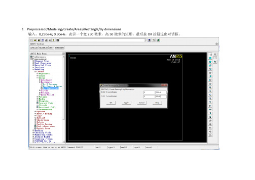
1.Preprocessor/Modeling/Create/Areas/Rectangle/By dimensions输入:0,250e-6; 0,50e-6。
表示一个宽250微米,高50微米的矩形。
最后按OK按钮退出对话框。
2.Preprocessor/Modeling/Material Props/Material models/Structural/Linear/Elastic/Orthotropic 输入弹性参数Preprocessor/Modeling/Material Props/Material models/Structural/Density 输入密度2330kg/m33.Preprocessor/Element Type/Add-Edit-Delete点击Add按钮,选择Shell,选择3D 4node 181,点击OK按钮退出。
4.Preprocessor/Sections/Shell/Lay-up/Add-EditThickness对话框输入2e-6,点击OK按钮退出。
5.Preprocessor/Meshing/Mesh ToolSize control: Global 点击Set按钮,在弹出的对话框的SIZE文本框中填入2.5e-6。
1236.Solution/Analysis Type/New Analysis/modal7. Solution/Analysis Type/Analysis OptionsNo. of modes to extract: 输入7。
去掉Expand mode shapes 的复选,使之从YES变为No。
在随后弹出的对话框中输入频率区间:0, 1e91328. Solution/Define Loads/Apply/Structural/Displacement/On Lines鼠标点选矩形左边的边,然后点击OK按钮退出。
在随后弹出的对话框中,VALUE文本框中输入09. Solution/Solve/Current LS 点击ok按钮开始计算。
ANSYS的最常用的命令解释
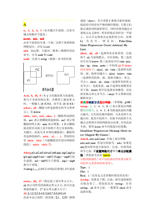
Aa,1,2,4,3(由关键点生成面,注意关键点的顺序不能乱)accat,na1,na2由多个面连结生成一个面,以便于体的映射网格划分。
详见lccatadd,加运算,只能对二维和三维图形用此命令,分为aadd和vaddaadd,注意与ovlap(搭接)命令的区别Acel,0,10,0(在y方向施加重力加速度,相当于考虑结构自重。
在模型上施加重力时,一般输入10或9.8,而不是-10或-9.8)aclear,all(删除与所选面相关的节点和单元),见kclearadele,na1,na2,ninc,1(删除所选择的面,na1表示要删除的起始面,na2表示要删除的终止面,ninc表示增量,1表示删除面及附在该面上而不依附于其它实体的线、关键点,此处为0时则仅删除面);删除所有选择的面时:adele,all,,,1;类似的还有kdele,ldele(只能删除没有划分网格的线段),ndele,edele等;Adrag,nl1,nl2,nl3,nl4,nl5,nl6,nlp1,nlp2,nlp3,n lp4,nlp5,nlp6由nl1…nl6沿着nlp1…nlp6扫掠生成面。
nl1…nl6相当于准线,nlp1…nlp6相当于母线。
如adrag,1,,,,,,2,3表示由线1沿着线2、3生成面aesize,all,27(指定面上划分单元大小,all表示对所有的面指定单元大小,也可以选择面的编号,27表示单元最大尺寸)AL,L1,L2,L3,L4,L5,L6,L7,L8,L9,L10此命令由已知的一组直线(L1,…L10)围绕成面(Area),至少须要3条线才能形成面,线段的号码没有严格的顺序限制,只要它们能完成封闭的面积即可。
同时若使用超过4条线去定义面时,所有的线必须在同一平面上,以右手定则来决定面积的方向。
如果L1为负号,则反向。
Paths:Main Menu>Preprocessor>Create>Arbitrary>By Linesallsel,all,all(选择所有实体类型,后面两个all为系统默认,可以省略;第二选项还可以为below,第三选项还可以volu、area、line、kp、elem、node。
- 1、下载文档前请自行甄别文档内容的完整性,平台不提供额外的编辑、内容补充、找答案等附加服务。
- 2、"仅部分预览"的文档,不可在线预览部分如存在完整性等问题,可反馈申请退款(可完整预览的文档不适用该条件!)。
- 3、如文档侵犯您的权益,请联系客服反馈,我们会尽快为您处理(人工客服工作时间:9:00-18:30)。
Block
Cylinder
Prism
Sphere
Cone
Torus
Main Menu: Preprocessor > -Modeling- Create >
Aug. 2005 By G.Z. Kang, SWJTU
Example: To construct a hollowed sphere
Main Menu: Preprocessor > Create > Sphere > By Dimensions ...
Typical steps for modeling:
Set the scheme of modeling Clarify the aim of analysis Outline the geometry feature of the model Choose suitable element type Ensure the fine and suitable mesh Chose the method of modeling Solid modeling Direct modeling Practical modeling
B
C
D
Aug. 2005 By G.Z. Kang, SWJTU
2. Geometry Modeling
Geometry Elements of ANSYS From lower to higher: • Keypoints • Lines • Areas • Volumes
I’ll just change this line
Y Z
X
Aug. 2005 By G.Z. Kang, SWJTU
Boolean operate The Boolean operate in ANSYS includes add, subtract, intersect, divide, glue and overlap.
How to construct the following model?
Add
A1+A2=A3
Aug. 2005 By G.Z. Kang, SWJTU
Subtract A1-A2=A3
Aug. 2005 By G.Z. Kang, SWJTU
Overlap
New areas A3, A4 and A5 are obtained from the overlap of A2 and A1.
Hale Waihona Puke . ModifyingElements
I’ll try to change this line again
Nodes
Volumes Areas Lines Keypoints
Oh No! It’s worse than before
Nodes
Lines
Keypoints
Aug. 2005 By G.Z. Kang, SWJTU
Main Menu> Preprocessor> Create> Nodes> in Active CS/on Working Plane/on Keypoints Main Menu> Preprocessor> Create>Elements> -Auto Number- Thru. Nodes Main Menu> Preprocessor> Create>Elements>- User Number- Thru. Nodes
Aug. 2005 By G.Z. Kang, SWJTU
Set Meshing options
Aug. 2005 By G.Z. Kang, SWJTU
Meshing Mesh tools
Aug. 2005 By G.Z. Kang, SWJTU
Main Menu> Preprocessor> -Meshing- Mesh> Smartsize Levels
Aug. 2005 By G.Z. Kang, SWJTU
Main Menu> Preprocessor> -Meshing- Shape & Size> -Global- Area Controls Lab=Expand and/or Trans.
Aug. 2005 By G.Z. Kang, SWJTU
wy y x wx
Origin
Grad-mesh, its space is adjustable
Aug. 2005 By G.Z. Kang, SWJTU
Utility Menu: WorkPlane >
Aug. 2005 By G.Z. Kang, SWJTU
Utility Menu: WorkPlane > WP Settings ...
Aug. 2005 By G.Z. Kang, SWJTU
Glue
Divide
A1
Divide
Common line
A2
A3
Aug. 2005 By G.Z. Kang, SWJTU
Extrude/Sweep Areas to Volumes
Aug. 2005 By G.Z. Kang, SWJTU
Chapter 2 Modeling
1. Introduction 2. Geometry Modeling 3. Element Attributes 4. Meshing 5. Modifying 6. Direct modeling
Aug. 2005 By G.Z. Kang, SWJTU
1. Introduction
Volumes Areas
OOPs!
Areas
Lines Keypoints
Lines Keypoints
Aug. 2005 By G.Z. Kang, SWJTU
Working plane A moveable reference plane, helpful to construct geometry model.
Main Menu: Preprocessor > Element Type > Add/Edit/Delete
Aug. 2005 By G.Z. Kang, SWJTU
Aug. 2005 By G.Z. Kang, SWJTU
Element real constant
Aug. 2005 By G.Z. Kang, SWJTU
Aug. 2005 By G.Z. Kang, SWJTU
Aug. 2005 By G.Z. Kang, SWJTU
Four kinds of modeling method
Option A 1. Build solid model. 2. Defeature as needed. 3. Export solid model. CAD Package ANSYS 1. Build solid model. 2. Mesh finite element model. 1. Import solid model 2. Complete or modify as needed. 3. Mesh finite element model. Build the nodes and elements directly as needed. 1. Build solid model 2. Defeature as needed. 3. Mesh finite element model. 4. Export finite element model. Import finite element model
Notes: • When a rectangle is constructed, it means nine geometry elements are automatically constructed, i.e., four keypoints, four lines, one area.
Oh yeah! I remember these entity things.
Aug. 2005 By G.Z. Kang, SWJTU
3. Element Attributes
Including: Material attributes Element type Element real constant
Aug. 2005 By G.Z. Kang, SWJTU
. .
Line Keypoints Area Line
Line
Line
. .
• The rectangle lies in workplane. • ANSYS will number all items automatically.
Aug. 2005 By G.Z. Kang, SWJTU
3-D primitives
4. Meshing
Three steps: Set Meshing attributes Set Meshing options Meshing: Free mesh and mapped mesh
Aug. 2005 By G.Z. Kang, SWJTU
Set Meshing attributes
Aug. 2005 By G.Z. Kang, SWJTU
6. Direct Modeling
Steps: Define nodes Define element attributes Define elements by existed nodes Modifying the elements
WZ WY WX
It can be obtained by intersect a hollowed sphere with a block.