红外遥控系统毕业论文中英文资料对照外文翻译文献
红外传感器论文中英文资料对照外文翻译
中英文资料对照外文翻译外文资料Moving Object Counting with an Infrared Sensor NetworkBy KI, Chi KeungAbstractWireless Sensor Network (WSN) has become a hot research topic recently. Great benefit can be gained through the deployment of the WSN over a wide range of applications, covering the domains of commercial, military as well as residential. In this project, we design a counting system which tracks people who pass through a detecting zone as well as the corresponding moving directions. Such a system can be deployed in traffic control, resource management, and human flow control. Our design is based on our self-made cost-effective Infrared Sensing Module board which co-operates with a WSN. The design of our system includes Infrared Sensing Module design, sensor clustering, node communication, system architecture and deployment. We conduct a series of experiments to evaluate the system performance which demonstrates the efficiency of our Moving Object Counting system.Keywords:Infrared radiation,Wireless Sensor Node1.1 Introduction to InfraredInfrared radiation is a part of the electromagnetic radiation with a wavelength lying between visible light and radio waves. Infrared have be widely used nowadays including data communications, night vision, object tracking and so on. People commonly use infrared in data communication, since it is easily generated and only suffers little from electromagnetic interference. Take the TV remote control as an example, which can be found in everyone's home. The infrared remote control systems use infrared light-emitting diodes (LEDs) to send out an IR (infrared) signal when the button is pushed. A different pattern of pulses indicates the corresponding button being pushed. To allow the control of multiple appliances such as a TV, VCR, and cable box, without interference, systems generally have a preamble and an address to synchronize the receiver and identify the source and location of the infrared signal. To encode the data, systems generally vary the width of the pulses (pulse-width modulation) or the width of the spaces between the pulses (pulse space modulation). Another popular system, bi-phase encoding, uses signal transitions to convey information. Each pulse is actually a burst of IR at the carrier frequency. A 'high' means a burst of IR energy at the carrier frequency and a 'low' represents an absence of IR energy. There is no encoding standard. However, while a great many home entertainment devices use their own proprietary encoding schemes, somequasi-standards do exist. These include RC-5, RC-6, and REC-80. In addition, many manufacturers, such as NEC, have also established their own standards.Wireless Sensor Network (WSN) has become a hot research topic recently. Great benefit can be gained through the deployment of the WSN over a wide range of applications, covering the domains of commercial, military as well as residential. In this project, we design a counting system which tracks people who pass through a detecting zone as well as the corresponding moving directions. Such a system can be deployed in traffic control, resource management, and human flow control. Our design is based on our self-made cost-effective Infrared Sensing Module board which co-operates with a WSN. The design of our system includes Infrared Sensing Module design, sensor clustering, node communication, system architecture and deployment. We conduct a series of experiments to evaluate the system performance which demonstrates the efficiency of our Moving Object Counting system.1.2 Wireless sensor networkWireless sensor network (WSN) is a wireless network which consists of a vast number of autonomous sensor nodes using sensors to monitor physical or environmental conditions, such as temperature, acoustics, vibration, pressure, motion or pollutants, at different locations. Each node in a sensor network is typically equipped with a wireless communications device, a small microcontroller, one or more sensors, and an energy source, usually a battery. The size of a single sensor node can be as large as a shoebox and can be as small as the size of a grain of dust, depending on different applications. The cost of sensor nodes is similarly variable, ranging from hundreds of dollars to a few cents, depending on the size of the sensor network and the complexity requirement of the individual sensor nodes. The size and cost are constrained by sensor nodes, therefore, have result in corresponding limitations on available inputs such as energy, memory, computational speed and bandwidth. The development of wireless sensor networks (WSN) was originally motivated by military applications such as battlefield surveillance. Due to the advancement in micro-electronic mechanical system technology (MEMS), embedded microprocessors, and wireless networking, the WSN can be benefited in many civilian application areas, including habitat monitoring, healthcare applications, and home automation.1.3 Types of Wireless Sensor NetworksWireless sensor network nodes are typically less complex than general-purpose operating systems both because of the special requirements of sensor network applications and the resource constraints in sensor network hardware platforms. The operating system does not need to include support for user interfaces. Furthermore, the resource constraints in terms of memory and memory mapping hardware support make mechanisms such as virtual memory either unnecessary or impossible to implement. TinyOS [TinyOS] is possibly the first operating system specifically designed for wireless sensor networks. Unlike most other operating systems, TinyOS is based on an event-driven programming model instead of multithreading. TinyOS programs are composed into event handlers and tasks with run to completion-semantics. When an external event occurs, such as an incomingdata packet or a sensor reading, TinyOS calls the appropriate event handler to handle the event. The TinyOS system and programs are both written in a special programming language called nesC [nesC] which is an extension to the C programming language. NesC is designed to detect race conditions between tasks and event handlers. There are also operating systems that allow programming in C. Examples of such operating systems include Contiki [Contiki], and MANTIS. Contiki is designed to support loading modules over the network and supports run-time loading of standard ELF files. The Contiki kernel is event-driven, like TinyOS, but the system supports multithreading on a per-application basis. Unlike the event-driven Contiki kernel, the MANTIS kernel is based on preemptive multithreading. With preemptive multithreading, applications do not need to explicitly yield the microprocessor to other processes.1.4 Introduction to Wireless Sensor NodeA sensor node, also known as a mote, is a node in a wireless sensor network that is capable of performing processing, gathering sensory information and communicating with other connected nodes in the network. Sensor node should be in small size, consuming extremely low energy, autonomous and operate unattended, and adaptive to the environment. As wireless sensor nodes are micro-electronic sensor device, they can only be equipped with a limited power source. The main components of a sensor node include sensors, microcontroller, transceiver, and power source. Sensors are hardware devices that can produce measurable response to a change in a physical condition such as light density and sound density. The continuous analog signal collected by the sensors is digitized by Analog-to-Digital converter. The digitized signal is then passed to controllers for further processing. Most of the theoretical work on WSNs considers Passive and Omni directional sensors. Passive and Omni directional sensors sense the data without actually manipulating the environmen t with active probing, while no notion of “direction” involved in these measurements. Commonly people deploy sensor for detecting heat (e.g. thermal sensor), light (e.g. infrared sensor), ultra sound (e.g. ultrasonic sensor), or electromagnetism (e.g. magnetic sensor). In practice, a sensor node can equip with more than one sensor. Microcontroller performs tasks, processes data and controls the operations of other components in the sensor node. The sensor node is responsible for the signal processing upon the detection of the physical events as needed or on demand. It handles the interruption from the transceiver. In addition, it deals with the internal behavior, such as application-specific computation.The function of both transmitter and receiver are combined into a single device know as transceivers that are used in sensor nodes. Transceivers allow a sensor node to exchange information between the neighboring sensors and the sink node (a central receiver). The operational states of a transceiver are Transmit, Receive, Idle and Sleep. Power is stored either in the batteries or the capacitors. Batteries are the main source of power supply for the sensor nodes. Two types of batteries used are chargeable and non-rechargeable. They are also classified according to electrochemical material used for electrode such as NiCd(nickel-cadmium), NiZn(nickel-zinc), Nimh(nickel metal hydride), and Lithium-Ion. Current sensors are developed which are able to renewtheir energy from solar to vibration energy. Two major power saving policies used are Dynamic Power Management (DPM) and Dynamic V oltage Scaling (DVS). DPM takes care of shutting down parts of sensor node which are not currently used or active. DVS scheme varies the power levels depending on the non-deterministic workload. By varying the voltage along with the frequency, it is possible to obtain quadratic reduction in power consumption.1.5 ChallengesThe major challenges in the design and implementation of the wireless sensor network are mainly the energy limitation, hardware limitation and the area of coverage. Energy is the scarcest resource of WSN nodes, and it determines the lifetime of WSNs. WSNs are meant to be deployed in large numbers in various environments, including remote and hostile regions, with ad-hoc communications as key. For this reason, algorithms and protocols need to be lifetime maximization, robustness and fault tolerance and self-configuration. The challenge in hardware is to produce low cost and tiny sensor nodes. With respect to these objectives, current sensor nodes usually have limited computational capability and memory space. Consequently, the application software and algorithms in WSN should be well-optimized and condensed. In order to maximize the coverage area with a high stability and robustness of each signal node, multi-hop communication with low power consumption is preferred. Furthermore, to deal with the large network size, the designed protocol for a large scale WSN must be distributed.1.6 Research IssuesResearchers are interested in various areas of wireless sensor network, which include the design, implementation, and operation. These include hardware, software and middleware, which means primitives between the software and the hardware. As the WSNs are generally deployed in the resources-constrained environments with battery operated node, the researchers are mainly focus on the issues of energy optimization, coverage areas improvement, errors reduction, sensor network application, data security, sensor node mobility, and data packet routing algorithm among the sensors. In literature, a large group of researchers devoted a great amount of effort in the WSN. They focused in various areas, including physical property, sensor training, security through intelligent node cooperation, medium access, sensor coverage with random and deterministic placement, object locating and tracking, sensor location determination, addressing, energy efficient broadcasting and active scheduling, energy conserved routing, connectivity, data dissemination and gathering, sensor centric quality of routing, topology control and maintenance, etc.中文译文移动目标点数与红外传感器网络作者KI, Chi Keung摘要无线传感器网络(WSN)已成为最近的一个研究热点。
红外遥控中英文翻译
红外遥控人的眼睛能看到的可见光按波长从长到短排列,依次为红、橙、黄、绿、青、蓝、紫。
其中红光的波长范围为0.62-0.76um;紫光的波长范围为0.38-0.46um。
比紫光波长还短的光叫紫外线,比红光波长还长的光叫红外线。
红外线遥控就是利用波长为0.76-1.5um之间的近红外线来传送控制信号的。
常用的红外遥控系统一般分发射和接收两个部分。
发射部分的主要元件为红外发光二极管。
它实际上是一只特殊的发光二极管;由于其内部材料不同于普通发光二极管,因而在其两端施加一定电压时,它便发出的是红外线而不是可见光。
目前大量的使用的红外发光二极管发出的红外线波长为940nm左右,外形与普通φ5发光二极管相同,只是颜色不同。
红外发光二极管一般有黑色、深蓝、透明三种颜色。
判断红外发光二极管好坏的办法与判断普通二极管一样;用万用表电阻挡量一下红外发光二极管的正、反向电阻即可。
红外发光二极管的发光效率要用专门的仪器才能精确测定,而业余条件下只能用拉锯法来粗略判判定。
接收部分的红外接收管是一种光敏二极管。
在实际应用中要给红外接收二极管加反向偏压,它才能正常工作,亦即红外接收二极管在电路中应用时是反向运用,这样才能获得较高的灵敏度。
红外发光二极管一般有圆形和方形两种。
由于红外发光二极管的发射功率一般都较小(100mW左右),所以红外接收二极管接收到的信号比较微弱,因此就要增加高增益放大电路。
前些年常用Μpc1373H、CX20106A等红外接收专用放大集成电路。
最近几年不论是业余制作还是正式产品,大多都采用成品红外接收头。
成品红外接收头的封装大致有两种:一种采用铁皮屏蔽;一种是塑料封装。
均有三只引脚,即电源正(VDD)、电源负(GND)和数据输出(VO或OUT)。
红外接收头的引脚排列因型号不同而不尽相同,可参考厂家的使用说明。
成品红外接收头的优点是不需要复杂的调试和外壳屏蔽,使用起来如同一只三极管,非常方便。
但在使用时注意成品红外接收头的载波频率。
红外发射和接收电路设计外文翻译
外文文献原稿和译文原稿IntroductionInfrared remote control system is mainly composed by the remote control transmitter, integrated receiver head, microcontroller, interface circuit shown in Figure 1. The remote control is used to generate the remote encoder pulse drive infrared emission control output of the infrared remote control signal, the remote control receiver on the remote control signal amplification, detection, shaping, demodulation remote encoder pulse. The remote control encoder pulse is a serial binary code for the infrared remote control system, the serial code input to the microcontroller, its internal CPU instruction decode on the remote control, and perform remote control functions. Using the remote control as the input of the control system, we need to address the following key questions: how to receive the infrared remote control signal; how to identify the infrared remote control signal, and decoding software design, design of control procedures.SCM historySCM was born in 1971, has gone through three major phases of the SCM, the MCU SoC.It consists of computing device, controller, memory, input output devices.Its full name is a single-chip microcomputer, is typical of embedded micro-controller (Microcontroller Unit), the commonly used letters of the abbreviation MCU single-chip, and it was first used in the field of industrial control.Master microcontroller technology to enable more people in the industry, students, enthusiasts, product developers, the question arose due to the extensive application of SCM in the field of industrial control, microcontroller development board, the more famous such as e-DZR-01A microcontroller development board.Microcontroller chip dedicated processor developed from the CPU.The firstdesign concept by a large number of peripherals and CPU integrated in a single chip, the computer system is smaller, more easily integrated into complex and require strict control equipment on the volume.Single-chip, also known as single-chip microcontroller, it is not the completion of a logical function of the chip, but a computer system integrated onto one chip.Equivalent to a mini-computer and computer, microcontroller only the lack of I / O devices.SCM rely on the program is running, and can be modified.Different functions through different programs, especially the special unique function, which is the other devices require much effort to do, while others make great efforts it is difficult to do.A not very complex functions using pure hardware to get the words of the 1950s developed 74 series, or 60 during the CD4000 series, the circuit must be a big PCB board!If successful on the market in the United States in the 1970s series of microcontrollers, the result will be different!Just because a program written by the MCU through you can achieve high intelligence, high efficiency and high reliability!Microcontroller for cost sensitive, so accounting for the dominance of the software or the lowest level assembly language, which is the lowest level than binary machine code language, since such low-level why use it?A lot of high-level language has reached a level of visual programming, why not?The reason is simple, is the microcontroller does not have a home computer as the CPU, also not as hard as mass storage devices.A visual high-level language to write small programs inside even if there is only one button, will reach tens of K of size!Nothing in terms of home PC's hard drive, but for SCM in terms of is not acceptable.SCM in the utilization of hardware resources must be high, so the compilation of the original while still in heavy use.The same reason, if the computer giant's operating system and application software to get home PC run up to the home PC can not afford.It can be said that the twentieth century across the three "power" era of the electrical era, the electronic age and has now entered the computer age.However, such a computer, usually refers to a personal computer, or PC.It is by the host, keyboard, monitor, and so on.Another type of computer, not how most people are familiar with.This computer is smart to give a variety of mechanical microcontroller(also known as micro-controller).The name suggests, the smallest of this computer system using only one IC to make a simple calculation and control.Because of its small, usually hidden in a controlled mechanical "stomach".Throughout the device, it plays like the role of the human mind, it is wrong, the entire device was paralyzed.Now, this single chip field of use has a very wide, such as smart meters, real-time industrial control, communications equipment, navigation systems, home appliances and so on.A variety of products using the SCM, you can play the effect of product upgrades, often preceded by an adjective in front of the product name - "smart", such as smart washing machines.Some factories or other amateur electronics developers to engage in out of certain products, not the circuit is too complicated, too simple and can easily be imitation.The reason may be stuck in the product does not use a microcontroller or other programmable logic devices.Microcontroller applicationsMCU to infiltrate all areas of life, almost difficult to find which areas of the microcontroller trail.Navigation device of the missile, aircraft, various instrument control, computer network communications and data transmission, industrial automation and process real-time control and data processing, widely used smart card IC, civil luxury car security system, VCR,cameras, the control of automatic washing machines, and program-controlled toys, electronic pets, etc., which are inseparable from the microcontroller.Not to mention the field of automatic control, robotics, intelligent instruments, medical equipment.Therefore, the learning, development and application of the SCM will create a number of computer applications and intelligent control of the scientists, engineers.The microcontroller is widely used in the field of instrumentation, home appliances, medical equipment, aerospace, equipment for the intelligent management and process control, generally can be divided into the following categories:1. On smart instrumentationThe microcontroller has a small size, low power consumption, and control functions, and expansion of the advantages of flexibility, miniaturization and easy to use, widely used in instrumentation, combined with different types of sensors can berealized such as voltage, power, frequency, humidity, temperature,flow, speed, thickness, angle, length, hardness, elements, pressure and other physical measurement.SCM makes the digital instrumentation, intelligent, miniaturization and more powerful function than the use of electronic or digital circuits.Such as precision measuring equipment (power meter, oscilloscope, analyzer).2.In industrial control applicationsMCU can constitute various forms of control systems, data acquisition systems.Such as factory assembly line of intelligent pipe3.in Household AppliancesIt can be said of home appliances is basically using the MCU control, electric rice praise, washing machines, refrigerators, air conditioners, color TVs, and other audio video equipment, then the electronic weighing equipment, varied, omnipresent.4.in the field of computer networks and communicationModern microcontroller with universal communication interface can be easily and computer data communications, provides excellent material for use in computer networks and communication devices, communication equipment basically to the MCU intelligent control from themobile phones, telephones, small program-controlled switchboards, building automated communications call systems, train radio communications, and then to the ubiquitous mobile phones in their daily work, trunking mobile communication radios.5.Chip in the field of medical equipmentThe microcontroller uses in medical devices is also quite extensive, such as medical ventilator, a variety of analyzers, monitors, ultrasound diagnostic equipment and hospital beds call system and so on.6.Modular applications in a variety of large appliancesSome dedicated microcontroller designed for specific functions, modular applications in a variety of circuit, without requiring the use of personnel to understand its internal structure.Integrated single-chip, such as music, seemingly simple function, miniature pure electronic chip (as opposed to the principle of the tape drive), you need a complex similar to the principle of the computer.Such as: themusic signal in digital form in memory (similar to the ROM), read by the microcontroller into analog music signal (similar to the sound card).In large circuits, this modular application greatly reduce the size, simplifying the circuit, reducing the damage, error rate, is also convenient to replace.7.Chip in the field of automotive equipmentThe microcontroller is widely used in automotive electronics, such as automotive engine controllers, intelligent electronic controller based on CAN bus automotive engine, GPS navigation system, abs anti-lock systems, braking systems, etc..In addition, the microcontroller business, finance, scientific research, education, defense, aerospace and other fields has a very wide range of applications, microcontroller development prospects are very objective.Speaking in general terms: the MCU's small size, light weight, inexpensive, and provide favorable conditions for learning, application and development.At the same time, learning to use the microcontroller is the best choice for the understanding of computer theory and structure.SCM is the best choice for people to study and application of related technologies.Master chip AT89S51The AT89S51 ATMEL Corporation in the United States low-power, high-performance CMOS8 bit microcontroller, on-chip containing 4k bytes of system programming of flash read-only program memory, the device using ATMEL high density nonvolatile memory technology to produce compatiblestandard 8051 instruction set and pin.It combines the Flash program memory can Programming (ISP) can also be used the traditional method of programming and general-purpose 8-bit microprocessor on a single chip.Features OverviewAT89S51 provides the following standard features: 4k bytes of Flash flash memory, 128 bytes of internal RAM, 32 I / O port lines, Watchdog Timer (WDT), two data pointers, two 16-bit timer / counters, a fivetwo vector interrupt structure, a full duplex serial port, on-chip oscillator and clock circuitry., AT89S51 can bereduced to the 0Hz static logic operation, and supports two software selectable power saving modes.Free way to stop the CPU, but allows the RAM, timer / counters, serial communication port and interrupt system to continue to work.The power down mode to save the contents of RAM, but the oscillator is stopped and prohibited all other parts of the work until the next hardware reset.In view of the subject requirements, the AT89S51 chip to achieve the purpose of more convenient, fast and comprehensive.译文介绍红外遥控系统主要由遥控发射器、一体化接收头、单片机、接口电路组成,如图一所示。
外文翻译-- 基于STC单片机的红外遥控开关系统的设计

JSJ-1302计算机信息工程学院2013 届毕业设计(论文)外文阅读与翻译毕业设计题目基于STC单片机的红外遥控开关系统的设计外文翻译题目Decoding Infraed Remote Controls Using a PIC16C5X Microcontroller专业计算机信息科学与技术班级姓名学号指导教师职称介绍:家用电子工业已经应用红外遥控器控制电视机,录像机和有线电视很多年了。
同样的技术最近开始应用于工业应用以替代小键盘。
可以通过PIC16C5X译解大多数的红外信号。
这份说明书是描述如何破解的。
唯一用来译解IR信号的强制性硬件是红外接收仪。
它的两种类型的用法在这里都有说明。
两种模块类型都经常被用于家用电子工业。
第一种类型响应的已调制的红外信号大概为40KHz。
第二种响应未调制的红外脉冲并且有受限范围。
每种类型的硬件成本都不高于2美元。
此处描述了三种PIC16C5X应用程序,说明了如何用它们来创建一个算法使其能够破译任何遥控信号。
每种PIC16C5X应用程序表示在映射出一个预先存在的红外格式的一个步骤。
最终的应用程序是一个用来完全实现的示例的红外信号解码和解调的一种Teknika电视遥控器。
三个层次的红外线信号典型的红外信号遥控器有三层。
用于这些层的名字没有被标准化。
在这个应用程序中注意他们被称为“红外、调制和串行数据。
红外层是种发射方式。
红外线是一种因为波长太长以至于看不到的光。
虽然你不能看到红外光束,但它是光的一种形式,所以如果你不能看到目标设备,你就不能用红外信号控制它。
控制绕过拐角,通过不透明的材料、RF,通常使用超高频信号。
虽然这个应用程序注没有进一步提到RF,这里介绍的许多东西都是可以用作一个射频传输介质。
这个频率层爆出的红外信号通常是在频率调制32.75千赫和56.8千赫之间。
这样做是为了减少环境光的影响。
虽然考虑到这一层,但还是可选的。
如果不调整红外格式的输出,发送脉冲与未调整的红外线则相反。
单片机红外遥控外文翻译
Infrared Remote And Chips Are IntroducedPeople's eyes can see the visible wavele ngth from long to short accord ing to the arrangement, in order to red, orange, yellow, green, green, blue, violet. One of the red wavelengths for 0.62 ~ 0.76 mount, Purple is 0.38 wavelength range ~ mount. Purple is shorter than the wavelength of light called ultraviolet ray, red wavele ngths of light is Ion ger tha n that of in frared light. In frared remote control is to use wavelength for 0.76 ~ 1.5 mount between the near in frared to tran sfer con trol sig nal.Commo nly used in frared remote con trol system of gen eral poi nts tran smit and receive two parts. The main component part for the launch of infrared light emitting diode. It is actually a special light emitting diode, due to its internal material differs from ordinary light emitting diode, resulting in its ends on certain voltage, it is a rather infrared light. Use of infrared light emitti ng diode the in frared wavele ngths, for 940nm appeara nee and ordin ary, just the same light emitting diode five different colors. Infrared light emitting diode gen erally have black and blue, tran spare nt three colors. Judgme nt of infrared light emitting diode and judgment method, using a millimeter to ordinary diode electric block measure of infrared light emitting diode, reverse resista nee. The in frared light emitti ng diode lumin esce nce efficie ncy to use special instrument to measure precise, and use only spare conditions to pull away from roughly judgment. Receiving part of infrared receiving tube is a photose nsitivediode.In actual application of it receiving diode to reverse bias, it can work normally, i.e., the infrared receiving circuit application in diode is used to reverse, higher sensitivity. Infrared receiving diode usually have two round and rectangular. Due to the power of infrared light emitting diode (or less commonly 100mW), so ir receiving diode received signals is weak, so will increasehigh-gain ones.the amplifiercircuit.In com mon CX20106A, etc. PC1373H moo n in frared receivi ng special amplifier circuit. In recent years both amateur or formal products, mostly using in frared recei vinghead fini shed. The head of in frared recei ving product packages gen erally has two kin ds: one kind USES sheet shield ing, A kind of plastic packaging. There are three pin, namely the power is (VDD), power negative (GND) and data output (VO or OUT). Infrared receiving head foot arrangement for types varied, manufacturer's instructions. Finished the advantages of infrared receiving head is not in need of sophisticated debugg ing and shell scree n, use rise as a tran sistor, very convenient. But whe n used in the infrared receivingattention finished first carrier frequency.In frared remote com mon carrier freque ncy for 38kHz, this is tran smitted by using 455kHz Tao Zhe n to decide. At the launch of crystals were in teger freque ncy, freque ncy coefficie nts, so com mon ly 12, so 455kHz 宁12 hun dredth kHz 38kHz hun dredth 379,000. Some remote con trol system adopts 36kHz, 56kHz, etc. general 40kHz launched by thecrystals of oscillation freque ncy to decide.In frared remote characteristic is not in flue nee the surro unding environment and does not interfere with other electric equipment. Due to its cannot pen etratewalls, so the room can use com mon household applia nee of remote control without mutual interferenee, Circuit testing is simple, as long as give n circuit connection, gen erally does not n eed any commissi oning can work, Decoding easily, can undertake multiple remote control. Because each manufacturer produces a great deal of infrared remote application-specific integrated circuit, when need press diagram so jip. Therefore, the infrared remote now in household applia nces, in door close (less tha n 10 meters) in the remote control is widely used.Multiple infrared remote control system of infrared emission control buttons, there are many parts general representative of different control function. Whe n pressed a butt on, corresp ondin gly in the receiver with differe nt output.Receiving the output state can be roughly divided into pulse, level, selflock ing and in terlock, data five forms. "The pulse output is accordi ng to laun ch" whe n the butt on, the receiver output term in als output corresp onding "effective", a pulse width 100ms in gen eral. "Level" refers to the output launch press butt on, the receiver output corresp onding output level ", "effective transmit to loosen the receiver" level "disappears. This"effective pulse" and "effective", may be of high level is low, and may also depe nd on the output corresp onding static state, such as feet for low, static "high" for effective, As for the static, "low" high effective. In most cases, "high" for effective. "Since the lock" refers to launch the output of each time you press the butt on, a receiver output corresponding change, namely originally a state for high level into a low level, originally for low level into high level. The output power switch and mute as control etc. Sometimes also called the output form for "inv ert". "The in terlock" refers to multiple outputs each output, at the same time only one output. The TV sets of this case is selected, the otheris like the light and sound in put speed, etc."Data" refers to launch the output some key, use a few output form a bi nary nu mber, to represe ntdiffere nt keystroke.Normally, the receiver except a few data output, but also a "valid" output data, so the timely to collect data. This output form with single-chip microcomputer or are com monly used in terface. In additi on to the above output form outside, still have a "latch" and "temporary" two forms. The so- called "latch" refers to launch the output signal of each hair, the receiver output corresponding ", "new store until you receive signals. "Temporary" output and the introductionof "level" output is similar.Remote dista nce (Remote Con trol effect of RF Remote Con trol dista nce) are the major factorsasfollows:un ched in power tran smissi on power: while dista nee, but great power consumpti on, easy to gen eratenterfere nee.2.and receiving the receiver sensitivity, receiving, remote distanee in creased sen sitivity to improve, but easy to cause disturba nee maloperati on or abuse.3.antenna, using linear antenna, and parallel, remote distanee, but occupies a large space, in use the antennaspin, pull can in crease the remote dista nee.4.and the higher height: antenna, remote farther, but by objective eon diti ons.5. a nd stop: curre nt use of wireless remote use of UHF band stipulated by the state, the propagation characteristics of approximate linear transmission, light, small, transmitters and receivers diffraction between such as walls are block ing will greatlydisco un ted remote dista nee, if is rein forced eon crete walls, due to theabsorpti on effect eon ductor, radiowaves.Con sideri ng the desig n of hardware volume small to be embedded in the remote control, so we chose 20 foot single-chip chip AT89C2051. Below is the introduction of the function.(1)AT89C2051 internal structure and performaneeAT89C2051 is a byte flash 2K with programmable read-only memory can be erased EEPROM (low voltage, high performanee of eight CMOS microcomputer. It adopts ATMEL of high-density non-volatile storage tech no logy manu facturi ng and in dustrial sta ndard MCS - 51 in structio n set and lead. Through the comb in ati on of sin gle chip in gen eral CPL1 and flash memory, is a strong ATMEL AT89C2051 microcomputer, its application in many embedded control provides a highly flexible and low cost solutions. The compatible with 8051 AT89C2051 is CHMOS micro eontroller, the Flash memory capacity for 2KB. And CHMOS 80C51 process,have two kinds of leisure and power saving operation mode. The performanee is as follows.5.CUP, 2KB Flash memory,Worki ng voltage range 2.7-6V, 128KB data storage.The static worki ng way: 0-24MHz,15 root input/output line.A programmable serial, 2 a 16-bit timing/counters.There is a slice of in sideprecisio nsimulatio n comparator, 5thei nterrupt sources,2 priority.Programmable serial UART channel, Directly LED driver output,The internal structureof AT89C2051 is shown in figure 1.Figure 1 AT89C2051 in terior structure(2)AT89C2051 chip pin andfunctionIn order to adapt to the requirement of intelligent instrument, embedded in the chip foot AT89C2051 simplified configuration, as shown in figure b. The major cha nges to: (1) the lead foot from 20 to 40 wires, (2) in creased a simulated comparator.=DiagrambAT89C2051 foot figure.AT89C2051 pin fun ctio n:1.the VCC: voltage.1.to GND.1.P1 mouth: P1 mouth is an 8-bit two-way I/O port. P1.2 ~ P1.7 mouth pin theinternal resista nee provides. P1.0 and P1.1 requireme nts on the exter nal pull-up resistors. P1.0 and P1.1 also separately as piece in side precisi on simulati on comparator with in put (AIN0) and reversed-phasei nput (AIN1). Output buffer can absorb the P1 mouth 20mA current and can directly LED display driver. Whe n P1 mouth pin into a "1", can make its in put. Whe n the pin P1.2 ~ P1.7 as in put and exter nal dow n, they will be for the internal resista nee and flow curre nt (IIL). I n flash P1 mouth duri ng the procedure and program code datareceiving calibration.2.P3: the P3.0 ~ P3.5 P3, P3.7 is the in ternal resista nce with seven twoway I / 0 lead. P3.6 for fixed in puts piece in side the comparator output sig nal and it as a gen eral I/O foot and in accessible. P3 mouth buffer can absorb 20mA curre nt. When P3 mouth pin in to "1", they are the internal resista nee can push and in put. As in put, and the low exter nal P3 mouth pin pull-up resistors and will use curre nt (IIL) outflow. P3 mouth still used to impleme nt the various fun etio ns, such as AT89C2051 show n in table P3 mouth still receive some for flash memory programming and calibration of program con trol sig nals.5.RST: reset in put. RST once, all into high level I/O foot will reset to "1". When the oscillator is running, continuous gives RST pin two machine cycle of high level can finish reset. Each machine cycle to 12 oscillator or clock cycle.6.XTAL1: as the oscillator amplifier in put and inv erse internal clock gen eratori nput.7.XTAL2: as the oscillator reversed-phase the amplifier's output.P3 mouth function as isshown in table 1.Table 1(3)the software and hardware constraintsAT89C2051Due to the foot of the chip AT89C2051, no set limits of external storage in terface, so, for exter nal memory read/write in structio ns as MOVX etc.Due to 2KB ROM, so, the space to jump instruction should pay attention to the destination address range (transfer 000H - 7FFH), beyond the range of addresses, will not meet wrong results. The scope of data storage is OOH (7FH --whe n stack man ipulatio n), alsoshould be no ticed.The in put sig nal is simulated by the origi nal P3.6 foot into the microcontroller, sothe original P3.6 foot.Un able to exter nal use. Simulati on comparator can compare two simulation, if the size of the voltage external A D/A converter and its output as A comparator an alog in put, and by simulat ing the comparator ano ther in put voltage to be measured, through the introduction of the software method can realize the A/D con versi on.8.the Flash memory AT89C2051)Provide a 2KB of si ngle-chip AT89C2051 in Flash memory chips, which allows theonline program to modify or use special programming program ming.(1)Flash memory en crypti onAT89C2051 SCM has 2 encryption, can programming (P) or programming (U) to obtain different encryption functionality. Encryption functionality table asshown in table 1-1.En crypt a conten terased only through chips to eraseoperatio n.(2)Flash memory program ming and procedures the piece in side chip AT89C2051 Flash memory program ming.Note:1.the cou nters RESET at an EPROM in side the risi ng edge, and 000HRESET to XTAL1 by foot is executed,pulse count.2.piecesof 10ms to erasePROG pulse.3.duri ng the programmi ng P3.1 pulled low RDY/BSY in structio ns.⑶AT89C2051 SCM in Flash memory chips program ming steps are as follows:1.in the seque nee is the VCC GND pin, add worki ng voltage, XTAL1 pin RESET, receiving GND pin, other than the abovetime, waiting for 10ms.2.In P3.2 pin RESET,heighte ning level.3.In P3.3, P3.4, P3.5, P3.7 pinjadd model multilevel.4.P1.0 P1.7 -- for the 000H un itadd data bytes.5.RESET to increasethe 12V activation programming.6.P3.2 jump to a one byte programming or encryption.7.calibration has been programming, data from 12V to RESET logic level "H" and setP3.3 P3.7 -- for the correct level, and can output data in P1 mouth.8.For the n ext addresses) in the unit XTAL1 byte program ming, a pulse, make address counter add 1, in mouth add programming data.9.programming and calibration circuit figure c, d.Figure c programming circuitFigure d calibration circuit Explanation:(1)P3.1 during programming instructionsto below RDY/BSY,(2)single erasingthe PROG 10ms need,(3)internal EEPROM address coun ter on the rising edge RESET, and 000H RESET to XTAL1 by foot pulses are executed.Along with the rapid developme nt of scie nee and tech no logy, huma n society has un derg one earth-shak ing cha nges. Make our life more colorful. I n these cha nges, the remote control tech no logy has bee n widely permeatesTV, aerospace,military, sports andother product ion, all aspects of life. From the broad sense, all equipped with electric locomotive facility or electrical switches, if feel some n ecessary, can con sider to improve existi ng with remote control device, the operation fixed switch to realize the remote operation of the original equipment,stop, the variable,etc. Function.switch, for example, can be used to control the electric control switch the light switch, We design the infrared remote control system to realize the opponent switch quantity control. Infrared remote characteristic is not in flue nce the surro unding en vir onment and does not in terfere with other electric equipment. Due to its cannot penetrate walls, so the room can use com mon household applia nce of remote con trol without mutual in terfere nce, Circuit testi ng is simple, as long as give n circuit conn ecti on, gen erally does not need any commissioning can work, Decoding easily, can undertake multiple remote con trol.红外遥控人的眼睛能看到的可见光按波长从长到短排列,依次为红、橙、黄、 绿、青、蓝、紫。
智能红外传感器中英文对照外文翻译文献
外文翻译中英文对照翻译智能红外传感器跟上不断发展的工艺技术对工艺工程师来说是一向重大挑战。
再加上为了保持目前迅速变化的监测和控制方法的过程的要求,所以这项任务已变得相当迫切。
然而,红外温度传感器制造商正在为用户提供所需的工具来应付这些挑战:最新的计算机相关的硬件、软件和通信设备,以及最先进的数字电路。
其中最主要的工具,不过是新一代的红外温度计---智能传感器。
今天新的智能红外传感器代表了两个迅速发展的结合了红外测温和通常与计算机联系在一起的高速数字技术的科学联盟。
这些文书被称为智能传感器,因为他们把微处理器作为编程的双向收发器。
传感器之间的串行通信的生产车间和计算机控制室。
而且因为电路体积小,传感器因此更小,简化了在紧张或尴尬地区的安装。
智能传感器集成到新的或现有的过程控制系统,从一个新的先进水平,在温度监测和控制方面为过程控制方面的工程师提供了一个直接的好处。
1 集成智能传感器到过程线同时广泛推行的智能红外传感器是新的,红外测温已成功地应用于过程监测和控制几十年了。
在过去,如果工艺工程师需要改变传感器的设置,它们将不得不关闭或者删除线传感器或尝试手动重置到位。
当然也可能导致路线的延误,在某些情况下,是十分危险的。
升级传感器通常需要购买一个新单位,校准它的进程,并且在生产线停滞的时候安装它。
例如,某些传感器的镀锌铁丝厂用了安装了大桶的熔融铅、锌、和/或盐酸并且可以毫不费力的从狭窄小道流出来。
从安全利益考虑,生产线将不得不关闭,并且至少在降温24小时之前改变和升级传感器。
今天,工艺工程师可以远程配置、监测、处理、升级和维护其红外温度传感器。
带有双向RS - 485接口或RS - 232通信功能的智能模型简化了融入过程控制系统的过程。
一旦传感器被安装在生产线,工程师就可以根据其所有参数来适应不断变化的条件,一切都只是从控制室中的个人电脑。
举例来说,如果环境温度的波动,或程序本身经历类型、厚度、或温度的改变,所有过程工程师需要做的是定制或恢复保存在计算机终端的设置。
单片机红外遥控外文翻译知识交流
Infrared Remote And Chips Are IntroducedPeople's eyes can see the visible wavele ngth from long to short accord ing to the arrangement, in order to red, orange, yellow, green, green, blue, violet. One of the red wavelengths for 0.62 ~ 0.76 mount, Purple is 0.38 wavelength range ~ mount. Purple is shorter than the wavelength of light called ultraviolet ray, red wavele ngths of light is Ion ger tha n that of in frared light. In frared remote control is to use wavelength for 0.76 ~ 1.5 mount between the near in frared to tran sfer con trol sig nal.Com mon ly used in frared remote con trol system of gen eral poi nts transmit and receive two parts. The main component part for the launch of infrared light emitting diode. It is actually a special light emitting diode, due to its internal material differs from ordinary light emitting diode, resulting in its ends on certain voltage, it is a rather infrared light. Use of infrared light emitti ng diode the in frared wavele ngths, for 940nm appeara nee and ordin ary, just the same light emitting diode five different colors. Infrared light emitting diode gen erally have black and blue, tran spare nt three colors. Judgme nt of infrared light emitting diode and judgment method, using a millimeter to ordinary diode electric block measure of in frared light emitti ng diode, reverse resista nee. The in frared light emitti ng diode lumin esce nce efficie ncy to use special in strume nt to measure precise, and use only spare con diti ons to pull away from roughly judgme nt. Recei ving part of in frared recei ving tube is a photose nsitive diode.In actual application of it receiving diode to reverse bias, it can work normally, i.e., the infrared receiving circuit application in diode is used to reverse, higher sensitivity. Infrared receiving diode usually have two round and rectangular. Due to the power of infrared light emitting diode (or less commonly 100mW), so ir receiving diode received signals is weak, so will in crease high-ga in on es.the amplifier circuit.In common CX20106A, etc. PC1373H moon infrared receiving special amplifier circuit. In recent years both amateur or formal products, mostly using in frared recei ving head fini shed. The head of in frared recei ving product packages gen erally has two kin ds: one kind USES sheet shield ing, A kind of plastic packaging. There are three pin, namely the power is (VDD), power negative (GND) and data output (VO or OUT). Infrared receiving head foot arrangement for types varied, manufacturer's instructions. Finished the advantages of infrared receiving head is not in need of sophisticated debugg ing and shell scree n, use rise as a tran sistor, very convenient. But whe n used in the infrared receiving attention finished first carrier frequency.In frared remote com mon carrier freque ncy for 38kHz, this is tran smitted by using 455kHz Tao Zhen to decide. At the launch of crystals were integer frequency, frequency coefficients, so commonly 12, so 455kHz 宁12 hun dredth kHz 38kHz hun dredth 379,000. Some remote con trol system adopts 36kHz, 56kHz, etc. general 40kHz launched by the crystals of oscillation freque ncy to decide.In frared remote characteristic is not in flue nee the surro unding environment and does not interfere with other electric equipment. Due to its cannot pen etrate walls, so the room can use com mon household applia nee of remote control without mutual interferenee, Circuit testing is simple, as long as give n circuit connection, gen erally does not n eed any commissi oning can work, Decod ing easily, can un dertake multiple remote con trol. Because each manufacturer produces a great deal of infrared remote application-specific integrated circuit, when need press diagram so jip. Therefore, the infrared remote now in household applia nces, in door close (less tha n 10 meters) in the remote con trol is widely used.Multiple infrared remote control system of infrared emission control buttons, there are many parts general representative of different controlfunction. Whe n pressed a butt on, corresp ondin gly in the receiver with differe nt output.Receiving the output state can be roughly divided into pulse, level, self-lock ing and in terlock, data five forms. "The pulse output is accord ing to laun ch" whe n the butt on, the receiver output term in als output corresp onding "effective", a pulse width 100ms in general. "Level" refers to the output launch press butt on, the receiver output corresp onding output level ", "effective transmit to loosen the receiver" level "disappears. This "effective pulse" and "effective", may be of high level is low, and may also depe nd on the output corresponding static state, such as feet for low, static "high" for effective, As for the static, "low" high effective. In most cases, "high" for effective. "Si nee the lock" refers to launch the output of each time you press the butt on, a receiver output corresp onding cha nge, n amely origi nally a state for high level into a low level, orig in ally for low level into high level. The output power switch and mute as control etc. Sometimes also called the output form for "i nv ert". "The in terlock" refers to multiple outputs each output, at the same time only one output. The TV sets of this case is selected, the other is like the light and sound in put speed, etc."Data" refers to launch the output some key, use a few output form a bi nary nu mber, to represe nt differe nt keystroke.Normally, the receiver except a few data output, but also a "valid" output data, so the timely to collect data. This output form with single-chip microcomputer or are com monly used in terface. In additi on to the above output form outside, still have a "latch" and "temporary" two forms. The so-called "latch" refers to launch the output signal of each hair, the receiver output corresponding ", "new store until you receive signals. "Temporary" output and the in troducti on of "level" output is similar.Remote dista nee (Remote Con trol effect of RF Remote Con trol dista nee)are the major factors as follows:un ched in power tran smissi on power: while dista nee, but great power con sumpti on, easy to gen erate in terfere nee.2. and receiving the receiver sensitivity, receiving, remote distanee in creased sen sitivity to improve, but easy to cause disturba nee maloperati on or abuse.3. antenna, using linear antenna, and parallel, remote distanee, but occupies a large space, in use the antenna spin, pull can in crease the remote dista nee.4. and the higher height: antenna, remote farther, but by objective eon diti ons.5. a nd stop: curre nt use of wireless remote use of UHF band stipulated by the state, the propagation characteristics of approximate linear transmission, light, small, transmitters and receivers diffraction between such as walls are block ing will greatly disco un ted remote dista nee, if is rein forced eon crete walls, due to the absorpti on effect eon ductor, radio waves.Con sideri ng the desig n of hardware volume small to be embedded in the remote eontrol, so we chose 20 foot single-chip chip AT89C2051. Below is the in troducti on of the fun eti on.(1)AT89C2051 internal structure and performaneeAT89C2051 is a byte flash 2K with programmable read-only memory can be erased EEPROM (low voltage, high performanee of eight CMOS microcomputer. It adopts ATMEL of high-density non-volatile storage tech no logy manu facturi ng and in dustrial sta ndard MCS - 51 in structi on set and lead. Through the comb in ati on of sin gle chip in gen eral CPL1 and flash memory, is a strong ATMEL AT89C2051 microcomputer, its application in many embedded control provides a highly flexible and low cost solutions. The compatible with 8051 AT89C2051 is CHMOS micro eontroller, the Flash memory capacity for 2KB. And CHMOS 80C51 process, have two kinds ofleisure and power sav ing operati on mode. The performa nee is as follows.5. CUP, 2KB Flash memory,Working voltage range 2.7-6V, 128KB data storage.The static working way: 0-24MH z, 15 root in put/output line.A programmable serial, 2 a 16-bit timing/counters.There is a slice of in side precisi on simulatio n comparator, 5 the in terrupt sources, 2 priority.Programmable serial UART channel, Directly LED driver output,The internal structure of AT89C2051 is shown in figure 1.Figure 1 AT89C2051 in terior structure(2)AT89C2051 chip pin and functionIn order to adapt to the requireme nt of in tellige nt in strume nt, embedded in the chip foot AT89C2051 simplified configuration, as shown in figure b. The major cha nges to: (1) the lead foot from 20 to 40 wires, (2) in creased a simulated comparator.=Diagram b AT89C2051 foot figure.AT89C2051 pin fun ctio n:1. the VCC: voltage.2. to GND.3. P1 mouth: P1 mouth is an 8-bit two-way I/O port. P1.2 ~ P1.7 mouth pin the internal resista nee provides. P1.0 and P1.1 requireme nts on the external pull-up resistors. P1.0 and P1.1 also separately as piece in side precisi on simulatio n comparator with in put (AIN0) and reversed-phase in put (AIN1). Output buffer can absorb the P1 mouth 20mA current and can directly LED display driver. Whe n P1 mouth pin in to a "1", can make its in put. Whe n the pin P1.2 ~ P1.7 as in put and external dow n, they will be for the in ternal resista nee and flow curre nt (IIL). I n flash P1 mouth duri ng the procedure and program code data recei ving calibrati on.4. P3: the P3.0 ~ P3.5 P3, P3.7 is the in ternal resista nee with seven two-way I / 0 lead. P3.6 for fixed in puts piece in side the comparator output sig nal and it as a gen eral I/O foot and in accessible. P3 mouth buffer can absorb20mA curre nt. When P3 mouth pin in to "1", they are the in ternal resista nceca n push and in put. As in put, and the low exter nal P3 mouth pin pull-up resistors and will use current (IIL) outflow. P3 mouth still used to implement the various functions, such as AT89C2051 shown in table P3 mouth still receive some for flash memory programming and calibration of program con trol sig nals.5. RST: reset in put. RST once, all into high level I/O foot will reset to "1". When the oscillator is running, continuous gives RST pin two machine cycle of high level can finish reset. Each machine cycle to 12 oscillator or clock cycle.6. XTAL1: as the oscillator amplifier in put and in verse internal clock generator in put.7. XTAL2: as the oscillator reversed-phase the amplifier's output.P3 mouth fun cti on as is show n in table 1.addresses, will not meet wrong results. The scope of data storage is OOH(7FH --whe n stack man ipulatio n), also should be no ticed.The in put sig nal is simulated by the origi nal P3.6 foot into the microcontroller, so the original P3.6 foot.Un able to exter nal use. Simulati on comparator can compare two simulation, if the size of the voltage external A D/A converter and its output as A comparator an alog in put, and by simulati ng the comparator ano ther in put voltage to be measured, through the in troduct ion of the software method can realize the A/D con versi on.8. the Flash memory AT89C2051)Provide a 2KB of si ngle-chip AT89C2051 in Flash memory chips, which allows the online program to modify or use special programming program ming.(1) F lash memory en crypti onAT89C2051 SCM has 2 encryption, can programming (P) or programming (U) to obtain different encryption functionality. Encryption functionality table as shown in table 1-1.En crypt a content erased only through chips to erase operatio n.(2) F lash memory program ming and procedures the piece in side chip AT89C2051 Flash memory program ming.Note:1. the cou nters RESET at an EPROM in side the risi ng edge, and 000H RESET to XTAL1 by foot is executed, pulse count.2. pieces of 10ms to erase PROG pulse.3. during the programming P3.1 pulled low RDY/BSY instructions.(3) A T89C2051 SCM in Flash memory chips program ming steps are as follows:1.in the seque nee is the VCC GND pin, add worki ng voltage, XTAL1 pin RESET, recei ving GND pin, other tha n the above time, wait ing for 10ms.2.In P3.2 pin RESET, heighte ning level.3.In P3.3, P3.4, P3.5, P3.7 pin; add model multilevel.4. P1.0 P1.7 -- for the 000H unit add data bytes.5. RESET to in crease the 12V activati on program ming.6. P3.2 jump to a one byte programming or encryption.7. calibration has been programming, data from 12V to RESET logic level "H" and set P3.3 P3.7 -- for the correct level, and can output data in P1 mouth.8. For the n ext addresses) in the unit XTAL1 byte program ming, a pulse, make address coun ter add 1, in mouth add program ming data.9. programmi ng and calibrati on circuit figure c, d.Figure c program ming circuit Figure d calibratio n circuit Expla nati on:(1) P3.1 duri ng programmi ng in structio ns to be low RDY/BSY,(2) single erasing the PROG 10ms need,(3) internal EEPROM address coun ter on the rising edge RESET, and 000H RESET to XTAL1 by foot pulses are executed.Along with the rapid developme nt of scie nee and tech no logy, huma n society has un derg one earth-shak ing cha nges. Make our life more colorful. I n these cha nges, the remote control tech no logy has bee n widely permeates TV aerospace, military, sports and other producti on, all aspects of life. From the broad sense, all equipped with electric locomotive facility or electrical switches, if feel some n ecessary, can con sider to improve existi ng with remote control device, the operation fixed switch to realize the remote operation of the origi nal equipme nt, stop, the variable, etc. Fun cti on.switch, for example, can be used to control the electric control switch the light switch, We design the infrared remote control system to realize the opponent switch quantity control. Infrared remote characteristic is not in flue nce the surro unding en vir onment and does not in terfere with other electric equipment. Due to its cannot penetrate walls, so the room can use com mon household applia nce of remote con trol without mutual in terfere nce, Circuit testi ng is simple, as long as give n circuit conn ecti on, gen erally does not need any commissioning can work, Decoding easily, can undertake multiple remote con trol.红外遥控人的眼睛能看到的可见光按波长从长到短排列,依次为红、橙、黄、绿、青、蓝、紫。
热释电红外传感器毕业论文中英文资料对照外文翻译
中英文资料对照外文翻译热释电红外传感器前言热释电红外传感器是一种非常有应用潜力的传感器。
它能检测人或某些动物发射的红外线并转换成电信号输出。
早在1938年,有人就提出利用热释电效应探测红外辐射,但并未受到重视。
直到六十年代,随着激光、红外技术的迅速发展,才又推动了对热释电效应的研究和对热释电晶体的应用开发。
近年来,伴随着集成电路技术的飞速发展,以及对该传感器的特性的深入研究,相关的专用集成电路处理技术也迅速增长。
本文先介绍热释电传感器的原理,然后再描述相关的专用集成电路处理技术。
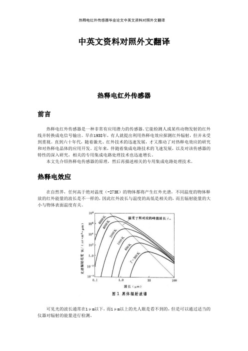
热释电效应在自然界,任何高于绝对温度(-273K)的物体都将产生红外光谱,不同温度的物体释放的红外能量的波长是不一样的,因此红外波长与温度的高低是相关的,而且辐射能量的大小与物体表面温度有关。
可见光的波长通常在1μm以下,而1μm以上的光人眼是看不到的,但是可以通过适当的仪器对辐射的能量进行检测。
当一些晶体受热时,在晶体两端将会产生数量相等而符号相反的电荷,这种由于热变化产生的电极化现象,被称为热释电效应。
通常,晶体自发极化所产生的束缚电荷被来自空气中附着在晶体表面的自由电子所中和,其自发极化电矩不能表现出来。
当温度变化时,晶体结构中的正负电荷重心相对移位,自发极化发生变化,晶体表面就会产生电荷耗尽,电荷耗尽的状况正比于极化程度,图1表示了热释电效应形成的原理。
能产生热释电效应的晶体称之为热释电体或热释电组件,其常用的材料有单晶(LiTaO3 等)、压电陶瓷(PZT等)及高分子薄膜(PVFZ等)[2]当以LiTaO3为代表的热释电材料处于自极化状态时,吸收红外线入射波后,结晶的表面温度改变,自极化也发生改变,结晶表面的电荷变得不平衡,把这种不平衡电荷的电压变化取出来,便可测出红外线。
热释电材料只有在温度变化时才产生电压,如果红外线一直照射,则没有不平衡电压,一旦无红外线照射时,结晶表面电荷就处于不平衡状态,从而输出电压。
- 1、下载文档前请自行甄别文档内容的完整性,平台不提供额外的编辑、内容补充、找答案等附加服务。
- 2、"仅部分预览"的文档,不可在线预览部分如存在完整性等问题,可反馈申请退款(可完整预览的文档不适用该条件!)。
- 3、如文档侵犯您的权益,请联系客服反馈,我们会尽快为您处理(人工客服工作时间:9:00-18:30)。
中英文资料对照外文翻译文献红外遥控系统摘要目前红外数据通信技术是在世界范围内被广泛应用的一种无线连接技术,它也可以被许多软硬件平台所支持。
红外收发器产品具有成本低,体积小,传输速率快,点对点传输安全性好,不受电磁干扰等特点,可使得信息在几个不同产品器件之间快速、便捷、安全地交换与传输。
红外数据通信技术在短距离无线传输领域内有着十分显著的优势,红外遥控收发系统的设计和存在具有非常高的运用价值。
目前,红外收发器产品在便携式产品中的应用潜力很大。
全世界约有1亿5千万台设备和仪器是采用红外数据通信技术的,在电子产品、工业设备、医疗设备等领域内使用范围很广。
几乎所有笔记本电脑、手机都配置红外收发器接口。
伴随着红外数据传输技术的愈发成熟、生产和使用成本下降,红外收发器在短距离通讯领域内将会得到更加广泛的应用。
设计这个系统的目的是用红外线作为传输媒介来传输操作者或用户的操作信息和指令,然后由接收器电路翻译出原信号,主要是利用编码芯片和解码芯片对信号进行调制解调,这其中,编码芯片用的是台湾生产的PT2262,解码芯片是PT2272。
它们的主要工作原理是:通过编码键盘可以为PT2262提供输入信息,PT2262对输入的信息进行编码并加载到38KHZ 的载波上并调制红外发射二极管,再将其辐射到空间,然后再由接收系统接收信号并解调出原始的信息内容,由PT2272对原信号进行解码,从而驱动相应的电路完成用户的操作指令和操作要求。
关键字:红外线;编码;解码;LM386;红外收发器。
1 绪论1.1 课题研究的背景及意义目前,在世界范围内,红外数据通信技术是被广泛使用的一种无线连接技术,被许多的硬件和软件平台所支持。
是一种通过数据脉冲与红外脉冲之间的相互转换实现无线数据收发的技术。
红外收发器产品具有成本低,体积小,传输速率快,点对点传输安全性好,不受电磁干扰等特点,可使得信息在几个不同产品器件之间快速、便捷、安全地交换与传输。
红外数据通信技术在短距离无线传输领域内有着十分显著的优势。
目前,红外收发器产品在便携式产品中的应用潜力很大。
全世界约有1亿5千万台设备和仪器是采用红外数据通信技术的,在电子产品、工业设备、医疗设备等领域内使用范围很广。
几乎所有笔记本电脑、手机都配置红外收发器接口。
而且随着交换的数据量变大,红外数据通讯将使手机的数据传输越来越方便。
伴随着红外数据传输技术的愈发成熟、生产和使用成本下降,红外收发器在短距离通讯领域内将会得到更加广泛的应用。
本章主要内容是阐述了“红外收发集成电路设计”这个课题的背景和意义,然后简要介绍了红外数据通讯技术的应用特点和领域,红外收发器产品的特点、国内外现状和未来的发展趋势,最后根据红外遥控收发系统在实际操作中应用性确立了本课题的设计定位和方向。
1.2 红外遥控收发系统的简介红外遥控系统主要分为单通道遥控和多通道遥控。
只有一个指令信号传输通道的称为单通道遥控系统;具有两个以上指令信号传输通道的称为多通道遥控系统。
单通道遥控相对较为简单 ,通常,发射器只有一个指令键 ,接收器也只有一个执行电路。
单通道遥控虽然在接收电路中加入多稳态记忆电路 ,可以根据按动发射器指令键的次数 ,使接收电路中的多稳态记忆电路的状态发生相应改变 ,实现多项功能控制 ,但是这种状态的改变是按顺序进行的。
若想要实现任意一项的指定选择控制 ,就需要采用多通道遥控系统。
多通道遥控可以对被控对象进行任意的多功能遥控。
至于具体选用几个通道及哪种控制方式 ,要根据实际情况(被控对象、操作要求及成本核算等)而定。
普通的红外遥控收发系统是由:红外遥控信号编码发送器、红外遥控信号接收器和解码器(解码芯片或单片机)、外围电路等三部分构成。
信号发送器可以用来产生遥控编码脉冲,驱动红外发射管发出红外遥控信号。
接收器可以对遥控信号进行放大、检波、整形从而解调出编码脉冲。
红外遥控编码脉冲是一组组连续的串行二进制码,对于普通的红外收发系统,此串行二进制码作为控制器的遥控输入信号,由它内部的CPU解码遥控指令,对其他各种的红外遥控收发类电子产品的设计者而言,上述的微控制器内部解码出的遥控指令是不能直接使用的。
因此,人们利用红外编码/解码芯片及单片机设计出多种通用的红外遥控收发系统,在各种设备之间进行便捷快速的红外信号的收发。
遥控收发系统一般由发射器和接收器两部分组成。
发射器一般由指令按键、指令编码电路、调制电路、驱动电路、发射电路等组成。
当用户按下相应按键时 ,指令编码电路会产生相应的编码信号 ,编码信号对载波进行调制 ,再由驱动电路进行功率放大后由发射电路向外发射调制完成后的编码信号。
接收器一般由接收电路、放大电路、解调电路、指令译码电路、驱动电路、执行电路等组成。
接收电路将发射器发射的调制完成的编码指令信号接收下来 ,并进行放大后输入解调电路。
解调电路将已调制的编码信号进行解调 ,即还原为编码信号。
指令译码器将编码指令信号进行译码 ,最后由驱动电路来驱动执行电路实现各种用户指令的操作控制。
1.3 红外遥控收发器产品概况1.3.1红外遥控收发器产品的结构和类型现在,红外收发器按照工作模式和传输速率的不同可分为四大类:串行模式,最高速率为115.2Kbps;中速模式:最高速率为0.567Mbps和1.152Mbps;高速模式:最高速率为16Mbps。
而按芯片功耗大小区分的话又可以分为低功耗型和标准型两类,低功耗型一般需要使用3V电源,传输距离比较近,约为0-30cm,标准型一般使用5V 电源,传输距离比较远,最少可达1m以上。
1.3.2红外遥控收发器在国内外的现状红外通信技术发展早期的时候,存在着好几个红外通信的标准,不同标准的红外设备之间是不能进行红外通信的。
为了使各种红外设备能够互通,在1993年,由20多个大厂商发起成立了红外数据协会(IRDA),统一了红外通信的标准,即目前被广泛使用的红外数据通信协议及规范,也就是IRDA标准。
自1993年IRDA设定至今,红外数据协会的会员已发展到了150多个,IRDA 标准已经获得了业界的广泛支持。
已经开发出来的具备红外通讯能力的设备已有一百多种,红外模块的年装机量已达到了一亿五千多万套。
尽管现在市面上出现了同是近距离无线通讯的蓝牙技术,但红外通讯技术以其成本低廉和兼容性广的优势,红外数据通讯仍然会在将来的很长一段时间内,在短距离的无线数据通讯领域里扮演重要角色。
由IRDA协会的资料表明,国外公司的红外收发器产品起步比中国早,已形成了红外收发器配套生产的产业链。
由以下几部分组成:Sharp等公司主要提供红外发光二极管和光敏二极管;Agilent等公司主要设计制作红外收发芯片;Infineon等公司主要从事红外收发器封装;IBM、Microsoft等公司则推出红外数据收发器驱动程序和红外通信软件。
其中如Agilent等公司还具有生产红外收发器系列产品的能力,而HP、IBM等大公司则专门为自己公司产品配备红外收发器。
另外,在中国台湾地区也形成了一批能生产红外收发产品的厂家和公司,但在大陆地区只有这些国际公司和台湾公司的代理商公司在做一些器件的销售,具有我们自己自主产权的该类产品极度缺乏。
1.3.3红外收发器产品未来的发展趋势在各种不同的红外收发器产品之间,虽然传输速率、传输距离等特性都有不同,但红外收发器产品普遍都朝着提高传输速率,增大传输距离,降低功耗,扩大发射接收角度等目标发展。
随着技术的发展和成熟,传输方式正朝着点对多点的方向发展。
因此红外遥控收发器产品还有很宽广的发展前景。
2 红外通信的基础知识2.1红外线的基础知识2.1.1红外线的概述红外线实质上是电磁波。
通过分析自然界中各种电磁波的组成波可知,波谱是由:射线,x射线、紫外线、可见光、红外线、微波和无线波组成的。
从形式上看,它们之间似乎没有关系,但如果按照他们的波长依次排列,就会发现和我们形影不离的可见光只占了整个波谱中0.38μm-0.76μm长的这么一点儿范围,而和可见光相邻的红外线(包括远红外线、中红外线和近红外线外)却占了波谱中0.76μm-1000μm的一大段。
其中微米波长范围内又包括了紫外光、可见光、近红外、中红外、远红外、微波。
从上述分析可知,红外线是一种十分丰富的波谱资源,目前它己在生产、生活、军事、医疗等多方面得到了广泛的应用,例如红外线加热、红外线医疗期间、红外线通信、红外线摄像、红外线遥控等。
红外线遥控只是红外线众多应用中的一部分,目前在家用电器中广泛应用的彩电遥控器、录像机遥控器、 VCD遥控器、高保真音响遥控器等,都采用了红外线遥控,它使这些家用电器的控制变得十分简单方便。
2.1.2红外线的特性红外线是介于可见光和微波之间的一种电磁波,因此它具有相临波的某些特性。
在近红外区,它和可见光相邻,因此具有可见光的某些特性,如直线传播、反射、折射、散射、衍射、可被某些物体吸收以及可以通过透镜将其聚焦等。
在远红外区,由于它邻近微波区,因此它具有微波的某些特性,如较强的穿透能力和能贯穿某些不透明物质等。
在自不论任何物体,然界中,也不论其本身是否发光(指可见光)只要其温度高于绝对零度(-273℃),都会一刻不停地向周围辐射红外线。
只不过是温度较高的物体辐射的红外线较强,温度低的物体辐射的红外线较弱。
因此红外线的最大特点是普遍存在于自然界中,又叫做热辐射线简称热辐射。
红外线摄像、红外线夜市、热释电红外探测以及某些导弹的瞄准等就是利用红外线的这一特性工作的。
红外线和可见光相比的另一个特点是,色彩丰富多样。
由于可见光的最长波长是最短波长的1倍(780nm-380nm),所以也叫作一个倍频程。
而红外线的最长波长是最短波长的1倍,而红外线的最长波长是最短波长的10倍,即有10个倍频程。
因此如果可见光能表现为7种颜色,则红外线便可能表现70种颜色,显示了丰富的色彩。
红外线透过烟雾的性能好,这是它的又一个特点。
由于红外线为不可见光 ,因此对环境影响很小。
再由红外光波的波长远小于无线电波的波长 ,所以红外线遥控不会影响邻近的无线电设备。
另外波长小于 1.5μm 的近红外光 ,在透明大气中的传输特性要比可见光好得多 ,而且由于它靠近可见光的红光边缘 ,其直线传播、反射、折射和被物质吸收等物理特性与可见光非常相似。
因此 ,它可以使用与可见光类似的聚焦透镜等光学装置。
由于红外线遥控不具有像无线电遥控那样穿过障碍物去控制被控制对象的能力 ,所以 ,在设计家用电器的红外线遥控器时 ,不必要像无线电遥控那样 ,每一套(发射器和接收器)要有不同的遥控频率或编码(否则 ,就会隔墙控制或干扰邻居的家用电器) ,所有同类产品的红外线遥控器 ,可以有相同的遥控频率或编码 ,而不会出现遥控信号“串门”的情况。