《物理双语教学课件》Chapter 24 Diffraction 衍射理论
大学物理双语课衍射课件

a=2f
λ
a
λ
x0
415 ×109 = 2 × 2.50 × = 2.25 ×10⁵ m = 0.023mm 9.2 ×10²
Example
1 a′ = a 2
焦平面上原来3 级暗纹处, 焦平面上原来 级暗纹处,现在明暗情况如何
a sin θ = 3λ
1 3 a sin θ = λ = (2m′ + 1) 1 λ 2 2 2
A
a
R
B
slit
a sin θ = 2
A
A 1
θ
C
L
P
Q
λ
2
o
P
B
λ/2
Hale Waihona Puke AbBR
A
A1
A2
θ L
C
λ/2
Q
a sin θ = 3
λ
2
o
B
2 .The positions on which all rays travel with angle θ
a sin θ = N
Dark fringe
a sin θ = ±2m
S
S
Large obstacle
Small obstacle
2. 惠更斯——菲涅耳原理 惠更斯—— ——菲涅耳原理
惠更斯原理
在波的传播过程中, 在波的传播过程中,波前上的每一点都可看作是发射 子波(次波)的波源,在其后的任一时刻, 子波(次波)的波源,在其后的任一时刻,这些子波的包 迹就成为新的波阵面。 迹就成为新的波阵面。
(sin φ+1 a )
φ
a
A
D
C
θ
大学物理课件-光的衍射

kmax
ab
2 106 5.9 107
3.4
kmax 3 最多能看到第三級譜線
[2]斜入射時:
i
j (a b)(sinj sin i ) k
最大級次滿足:
(a b)(sin900 sin 300) kmax
(a b) 3 2 106 3
kmax
2
2 5.9 107
5.1
B
2
(3)條紋寬度
暗條紋到中心的距離為:
l
xk sinjk f jk f
f k
a
x1 l0
中央明紋寬度:l0
2x1
2
f
a
xk
其他明紋寬度:l
(4)白光衍射
xk1
xk
f
a
白光照射時,中央為白色條紋,兩側對
稱排列形成彩色條紋。
15.3 光柵衍射(grating diffraction)
一、衍射光柵
[2]第一明紋寬度,兩個第三級暗紋距離;
解:[1]
a sin j (2k 1)
P
j
sin j
2
tgj
x
a=1.0mm
O
f
則有:
f=100cm
(2k 1)λf
x 1max
2a
7.5 10 4 m
由暗紋公式: a sin j k
k 3
x3min
kλf a
1.5 10 3 m
[2]第一級明紋寬度是
條紋重合說明j相同則有
( 2k'1)' ( 2k 1)
代入得:
λ 2k 1 λ 45001010m (2k 1)
0
0
2024版大学物理光的衍射课件

大学物理光的衍射课件CONTENTS •光的衍射现象与基本原理•典型衍射实验及其分析•衍射光栅及其应用•晶体中的X射线衍射•激光全息与光学信息处理•总结与展望光的衍射现象与基本原理01光在传播过程中遇到障碍物或小孔时,偏离直线传播的现象。
包括菲涅尔衍射和夫琅禾费衍射等。
衍射是光波遇到障碍物后产生的偏离直线传播的现象,而干涉是光波叠加产生的加强或减弱的现象。
衍射现象的定义衍射的种类衍射与干涉的区别光的衍射现象惠更斯-菲涅尔原理惠更斯原理介质中任一波面上的各点,都可以看做发射子波的波源,即可作为新波源产生球面次波,其后任意时刻这些子波的包迹面就是新的波面。
菲涅尔原理在光传播的过程中,光波前上的每一点都可以看作是新的光源,发出球面次波,这些次波在空间中相遇并相互叠加,形成新的光波前。
惠更斯-菲涅尔原理的意义解释了光的衍射现象,并为波动光学的发展奠定了基础。
03基尔霍夫衍射公式的应用用于计算各种衍射现象的振幅和相位分布,如单缝衍射、双缝干涉等。
01基尔霍夫衍射公式的表达式描述了光波在衍射屏上的振幅分布与观察屏上的振幅分布之间的关系。
02公式中各物理量的含义包括衍射屏上的复振幅分布、观察屏上的复振幅分布、光源到衍射屏的距离、衍射屏到观察屏的距离等。
基尔霍夫衍射公式典型衍射实验及其分析02单缝衍射实验装置与原理01通过单缝的衍射实验,可以观察到光波通过狭窄缝隙后的衍射现象。
实验装置包括光源、单缝、屏幕等部分。
当单色光波通过宽度与波长相当的单缝时,会在屏幕上形成明暗相间的衍射条纹。
衍射条纹特点02单缝衍射条纹呈现中间亮、两侧暗的特点。
亮条纹的间距随着衍射角的增大而减小,暗条纹则相反。
条纹间距与单缝宽度、光波长以及观察距离有关。
衍射公式与计算03根据惠更斯-菲涅尔原理,可以推导出单缝衍射的公式,用于计算衍射条纹的位置和强度分布。
双缝干涉与衍射实验装置与原理双缝干涉与衍射实验采用双缝作为分波前装置,通过两束相干光波的叠加产生干涉和衍射现象。
光的衍射的基本理论优秀PPT

②K(θ)表示了子波的振幅在各个方向上是不同的,其值在0与1之 间 。 如 果 一 平 行 光 垂 直 入 射 到 ∑ 上 , 则 cos(n,l) = - 1 , cos(n,r)=cosθ.因此,当θ等于0时,K(θ)=1,这说明在波面法线 方向上的子波贡献最大。
3.1 衍射的基本理论
3.1.4 基尔霍夫公式的近似 确定一个特定衍射问题的严格解是很困难的,必须根据实际条
E ~(P)iz1E ~(Q )eikd r
3.1 衍射的基本理论
3.1.4 基尔霍夫公式的近似
E(P) i
E(Q)eikrd
z1
注: 由于指数中的r所 影响的是子波场的相位, r的微小变化都会引起相 位很大的变化,所以r未 用z1代替。
3.1 衍射的基本理论
3.1.4 基尔霍夫公式的近似
惠更斯原理是最早描述光波传 播过程的一个原理。这个原理指 出:在光波场中,某一时刻t的光 波波前上每一点都是一个子波波 源,发射于波。在新的t +Δ t时刻 的波前是这些子波的包迹面,波 阵面的法线方向就是该波的传播 方向。惠更斯原理没有给出新波 前上光波振幅,无法说明衍射现 象。
3.1 衍射的基本理论 3.1.2 惠更斯-菲涅尔原理
10
5
0
-5
-10
-10
-5
10
5
0
-5
0
5
10
-10
-10
-5
0
圆孔衍射现象
5
10
3.1 衍射的基本理论 3.1.1 光衍射现象
2. 衍射与干涉的不同
光的衍射现象与光的干涉现象就其实质来讲,都是相干 光波叠加引起的光强的重新分布,不同的是,干涉是有限个 相干光波的叠加,衍射是无限个相干光波的叠加。
diffraction

2π 2π = = 0.4m Wavelength k 5π Period T = 2π = 2π = 0.2s Frequency f = 1 = 1 = 5 Hz ω 10π T 0.2
The speed of the wave v = ω = 10π = 2m / s
k 5π
(b) What is the transverse velocity u of the element of the string at x = 0.05 m and t = 12 s? Solution: The transverse velocity u is the rate at which the displacement y of the element is changing, Substituting numerical values, we obtain u = (10π )(0.04)cos(0.05 × 5π + 10π × 12) = 0.89 m/s (c) What is the transverse acceleration ay of the same element at that time in part (b)? Solution: The transverse acceleration ay is the rate at which the transverse velocity of the element is changing,
v= FT
µ
11-5 Energy Transported by Waves Kinetic Energy An element of the string of mass dm, has kinetic energy 1 2
光的衍射讲义
E~x, y i
z1
E~x1
,
y1
exp
ik
rdx1dy1
y1
y
进一步的计算需要将 exp( ikr )中的r表示成 (x,y,z)的函数,指数项中
x1
r Q
C z1
x P P0
r不能像振幅项中r一样 用z1来表示
K
E
孔径 的衍射
21
2、菲涅耳近似(对位相项的近似)
r
z12 (x x1 )2 y y1 2 z1
光孔尺寸与衍射
一、>1000时,衍射效应很弱,光线几乎直线传播。 但在影界边缘,衍射现象仍不可忽略。
二、1000 >> 时,衍射现象显著,出现了与光孔 形状对应的衍射图样。
三、 ~ 衍射效应过于强烈,只看到干涉。 四、< 向散射过渡。
其中:光孔线度,波长
干涉和衍射的联系与区别
本质上干涉和衍射都是波的相干叠加,没有区别。
R
( n,l )
( n,r )
r
P
则K 1 1 cos
2
5.3 菲涅耳衍射和夫琅禾费衍射
一、两类衍射现象的特点
A区:几何光学区,即光斑边缘清晰,大小与障碍物的通光口径基本相同; B区:菲涅耳衍射,即光斑边缘模糊,光斑内有明暗相间的条纹,观察屏沿 轴向后移动,光斑不断扩大,光斑内条纹数减少,中心有亮暗交替的变化; C区:夫琅禾费衍射,观察屏沿轴前后移动,光斑只有大小的变化,其形式 不变。
y1
2
z1+
x1x z1
y1 y
x2 y2 2z1
x12 y12 2z1
当 k x12 y12 max p 2z1
取上式前三项
衍射原理
~~ 2 I (P) = EE* = E (P)
菲涅耳-基尔霍夫衍射积分公式
基尔霍夫对菲涅耳的积分公 式作了严格的数学论证, 式作了严格的数学论证,得 到以下结论: 到以下结论: (1)确定了积分常数和倾斜 因子的表达式
d∑
R
θ0 Q θ
n
r
~ dU(P)
P
C=
i
λ
从同一波阵面上各点所发出的子波, 从同一波阵面上各点所发出的子波,经传播而在 空间某点相遇时,也可相互叠加产生干涉现象. 空间某点相遇时,也可相互叠加产生干涉现象.
若取 t =0 时刻波阵面上各 点发出的子波初相为零, 的子波初相为零, 则面元 dS 在P 点引起的 光振动为: 光振动为:dE
n
θ r S dS
t + t
t 时刻波面
波传播方向
ut
t
t+t时刻波面 时刻波面 平面波
球面波
惠更斯— 惠更斯—菲涅耳原理
波的传播过程,可以看作是次波中 次波中 衍生出新的次波 次波的过程 心不断地衍生 衍生 次波
波 的 衍 射
水 波 的 衍 射
惠更斯原理可定性地说明衍射现象, ⒉ 惠更斯原理可定性地说明衍射现象,但不能解释光 的衍射图样中光强的分布. 的衍射图样中光强的分布.也就是没有回答光振幅的传播问
dS d E =C K θ ) ( cos (ω t r
2 r π
λ
)
P点的光振动(惠更斯原理的数学表达)为: 点的光振动(惠更斯原理的数学表达) 点的光振动
A(Q) 2π E( p) = C∫ K(θ ) cos(ωt )dS S r λ
~ A(Q) i(krωt ) E = C∫ K(θ ) e dS S r
衍射

指的是光源-衍射屏、衍射屏-接受屏之间的距离均为有限远,或其中之一为有限远的场合,或者说,球面波 照明时在有限远处接收的是菲涅尔衍射场。例如:圆孔衍射、圆屏衍射菲涅尔衍射、泊松亮斑
单缝夫朗和费衍射指的是衍射屏与两者的距离均是无限远的场合,或者说,平面波照明时在无穷远处接收的 是夫琅禾费衍射场。概略的看,菲涅尔衍射是近场衍射,而夫琅禾费衍射是远场衍射。不过,在成像衍射系统中, 与照明用的点光源相共轭的像面上的衍射场也是夫琅禾费衍射场,此时,衍射屏与点光源或接收屏之距离在现实 空间看,都是很近的。
感谢观看
衍射
波的一种物理现象
01 研究历史
03 几何理论
目录
02 光的
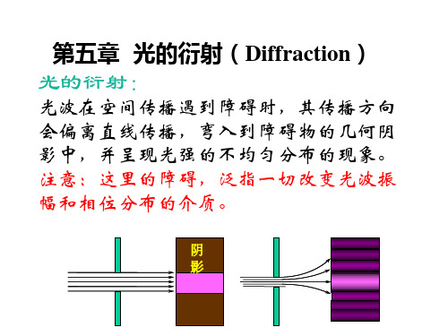
衍射(英语:diffraction)是指波遇到障碍物时偏离原来直线传播的物理现象。
在经典物理学中,波在穿过狭缝、小孔或圆盘之类的障碍物后会发生不同程度的弯散传播。假设将一个障碍 物置放在光源和观察屏之间,则会有光亮区域与阴晦区域出现于观察屏,而且这些区域的边界并不锐利,是一种 明暗相间的复杂图样。这现象称为衍射,当波在其传播路径上遇到障碍物时,都有可能发生这种现象。除此之外, 当光波穿过折射率不均匀的介质时,或当声波穿过声阻抗(acoustic impedance)不均匀的介质时,也会发生类 似的效应。在一定条件下,不仅水波、光波能够产生肉眼可见的衍射现象,其他类型的电磁波(例如X射线和无 线电波等)也能够发生衍射。由于原子尺度的实际物体具有类似波的性质,它们也会表现出衍射现象,可以通过 量子力学进行研究其性质。
- 1、下载文档前请自行甄别文档内容的完整性,平台不提供额外的编辑、内容补充、找答案等附加服务。
- 2、"仅部分预览"的文档,不可在线预览部分如存在完整性等问题,可反馈申请退款(可完整预览的文档不适用该条件!)。
- 3、如文档侵犯您的权益,请联系客服反馈,我们会尽快为您处理(人工客服工作时间:9:00-18:30)。
Chapter 24 DiffractionWhen monochromatic light from a distance source (or a laser) passes through a narrow slit and is then intercepted by a viewing screen, the light produces on the screen a diffraction pattern like that in figure.This pattern consists of abroad and intense (verybright) central maximum and a number of narrower and less intense maxima (called secondary or side maxima) to both sides. In between the maxima are minima.24.1 Diffraction by a Single Slit1.Let us consider how planewaves of light ofwavelength arediffracted by a single longnarrow slit of width a in anotherwise opaque screen B,as shown in cross section infigure (a).2.We can justify the centralbright fringe seen in figureby noting that the waves from all points in the slit travel about the same distance to reach the center of the pattern and thus are in phase there. As for the other bright fringes, we can say only that they are approximately halfway between adjacent dark fringes.3. To locate the first dark fringe at point P 1, we first mentally divide the slit into two zones of equal widths 2/a . Then we extend to P 1 a light ray r 1 from the top point of the top zoneand a light ray r 2 fromthe top point of thebottom zone . A centralaxis is drawn from thecenter of the slit toscreen C, and P 1 islocated at an angle θ tothat axis. The first darkfringe can be located at2sin 2λθ=a . It meansλθ=sin a . 4. To find the second darkfringes above and belowthe central axis, wedivide the slit into four zones of equal widths 4/a , as shown in above figure (a). We then extend rays r 1, r 2, r 3, and r 4 from the top points of the zones to point P 2, the location of the second dark fringe above the central axis. The second dark fringe can then be located at 2sin 4λθ=a or λθ2sin =a .5. The dark fringes can be located with the following general equation : ,3,2,1sin ==m for m a λθ. Above equation is derived for the case of a D >>. However, it also apply if we place a converging lens between the slit and the viewing screen andthen move the screenin so that it coincideswith the focal plane ofthe lens .6. Intensity in single-slitdiffraction : We canprove the expressionfor the intensity I ofthepattern as2)sin (ααm I I =, whereθλπαsin a =, and m I isthe greatest value ofthe intensity in thepattern. And it occurs at the central maximum (where 0=θ). Figure shows plots of the intensity of a single-slit diffraction pattern for three different slit widths .24.2 Diffraction by a Circular Aperture1. Here we consider diffractionby a circular aperture , throughwhich light can pass. Figureshows the image of a distantpoint source of light formedon photographic film placed inthe focal plane of a converginglens. (1) The image is not a point, but a circular disk surrounded by several progressively fainter secondary rings.(2) The first minimum for the diffraction pattern of a circular aperture of diameter d is given by d λθ22.1sin =.2. Resolvability : In figure (b) the angular separation of the two point sources is such that the central maximum of the diffraction patter of one source is centered on the first minimum of the diffraction pattern of the other , a condition called Rayleigh ’s criterion for resolvability . Thus two objects that are barely resolvable by this criterion must have an angular separation d R λθ22.1sin 1-=.3. When we wish to use a lens to resolve objects of small angular separation, it is desirable to make the diffraction pattern as small as possible. This can be done either by increasing the lens diameter or by using light of a shorter wavelength .24.3 Diffraction by a Double Slit1. In the double-slit experiment, we implicitly assumed that the slits were narrow compared to the wavelength of the light illuminating them; that is, λ<<a . For such narrow slits, the central maximum of the diffraction pattern of either slit covers the entire viewing screen . Moreover, the interference of light from the two slits produces bright fringes that all have approximately the same intensity .2. In practice with visible light, however, the condition λ<<a isoften not met . For relatively wide slits, the interference of light from two slits produces bright fringes that do not have the same intensity. In fact, their intensity is modified by thediffraction of the lightthrough each slit . See thefigures.3. With diffraction effects taken into account, the intensity of a double-slit interference pattern is given by22)sin )((cos ααβm I I =, in whichθλπβsin )(d = and θλπαsin )(a =.24.4 Diffraction Gratings1. One of the most usefultools in the study of lightand of objects that emit and absorb light is the diffraction grating . Somewhat like the double-slit arrangement, this device has a much greater number N of slits, often called rulings , perhaps as many as several thousand per millimeter .2. With monochromatic light incident on a diffraction grating, if we gradually increase the number of slits from two to a large number N. The maxima are now very narrow (and so called lines ). They are separated by relatively wide dark regions , as shown in above figure.3. The separation between rulings is called the grating spacing . The maxima-lines are located at ,3,2,1,0,sin ==m for m d λθ, in which the integers are then called the order numbers , and the lines are called the zeroth-order line (the central line , with m=0), the first-order line, the second-order line, and so on.4. Width of the lines: (1) we measure the half-width of the central line as the angle hw θ∆ from the center of the line at0=θ outward to where the line effectively ends and darknesseffectively begins with the first minimum. (2) The half-width of the central line is given asNd hw λθ=∆. (3) The half-width of any other line is given as θλθcos Nd hw =∆.5.An application of diffraction gratings: Figure shows a simplegrating spectroscope in which a grating is used to determine the wavelength.24.5 X-Ray Diffraction1.X rays are electromagnetic radiationwhose wavelengths are of the orderof o A1. Figure shows that x rays areproduced when electrons escapingfrom a heated filament F are accelerated by a potential difference V and strike a metal target T.2.Bragg’s law: ,3,2,1θ.dλ2=msinfor=m3.Figure shows how the interplanerspacing d can be related to the unitcell dimensiona:。