节电器太京说明书(中文)
KYD系列电动机节电器使用说明书(直接起动)

产品保用一年,如需服务请联络佛山市金顺利自动化控制有限公司或设在各地区的经 销处。如有不明之处请拨打本公司技术咨询手机:18098190262,本公司有关工程技术人员 将随时为您解答,并竭诚为您服务。欢迎您继续采用开源公司产品。
并请在安装前仔细阅读本说明书,节电器非正常使用造成的产品损坏不属保用之列。
(2) 对于 JO2 系列电动机接线盒(D1~D6 均为节电器出线) A 相:D1(头)D4(尾) B 相:D2(头)D5(尾) C 相:D3.(头)D6(尾)
(3) 节电器引出线 6 条分别为: 红色线接 U1 或 D1、黄色线捷 V1 或 D2、蓝色线接 W1 或 D3、 白色线接 W2 或 D6、黑色线接 U2 或 D4、绿色线接 V2 或 D5。 3.、工作电源:AC(220V 或 380V)±15%、50HZ。 4、工作方式:不间断工作制,Y/△转换自动循环。 5、适用环境温度:40℃~50℃ 6、Y—△转换:当负载率为 40%以上,△—Y 转换:当负载率为 40%以下。 7、电流精度:≤±2%、电流分辨率:1A
使用须知:
为了您的安全,本说明书有[危险]、[注意]等符号提醒您在搬运、安装、运转、检查 节电器时的安全防范事项,请您配合,使节电器的使用更加安全。
□危险:错误使用时,可能造成人员伤亡。
△注意:错误使用时,可能造成节电器或机械损坏。
□危险
﹒不可在带电时接线、拆线及检查零部件。 ﹒请勿自行拆装或更改节电器内部的连接线、线路和零件。
本说明书分别介绍了产品型号、安装配线、参数设定、操作运行及故障排 除等相关事项,为了充分发挥该产品的优越性能,确保使用者的安全,延长节 电器的寿命,请您在使用前详细阅读本说明书,并请妥善保存。
本说明书无法解答时,请联络金顺利公司或设在各地区的经销处。我们将 竭诚为您服务,并欢迎您继续采用金顺利公司产品。
美国Eaton公司产品说明书:Eaton PDG10C0045TFFJ型号的电磁保护罩箱断路器

Eaton PDG10C0045TFFJEaton Power Defense molded case circuit breaker, Globally Rated, Frame 1, Four Pole (0% N), 45A, 18kA/480V, T-M (Fxd-Fxd) TU, Standard Line and Load (PDG1X4T125)Eaton Power Defense molded case circuit breakerPDG10C0045TFFJ 78667930533176 mm 139.7 mm 101.6 mm 2.22 kg Eaton Selling Policy 25-000, one (1) year from the date of installation of theProduct or eighteen (18) months from thedate of shipment of the Product,whichever occurs first.RoHS Compliant IEC 60947-2CSAUL 489CCC MarkedProduct NameCatalog Number UPCProduct Length/Depth Product Height Product Width Product Weight WarrantyCompliancesCertifications45 AComplete breaker 1Four-pole (0% N)PD1 Global Class AT-M (Fxd-Fxd) TU600 Vac600 V0% neutral protection Standard Line and Load18 kAIC at 480 Vac18 kAIC @480V (UL)10 kAIC Icu @250 Vdc20 kAIC Icu/ 20 kAIC Ics/ 42 kAIC Icm @380-415V (IEC) 25 kAIC @240V (UL)10 kAIC @600V (UL/CSA)25 kAIC Icu/ 25 kAIC Ics/ 52.5 kAIC Icm @240V (IEC) 10 kAIC Icu @125 Vdc Eaton Power Defense MCCB PDG10C0045TFFJ 3D drawingConsulting application guide - molded case circuit breakersPower Defense technical selling bookletPower Defense brochurePower Defense molded case circuit breaker selection poster Power Defense molded case circuit breakers - Frame 1 product aidMolded case circuit breakers catalogPDG1 CSA certificationPDG1 CCC certificationPDG1 UL authorizationAmperage RatingCircuit breaker frame type FrameNumber of poles Circuit breaker type ClassTrip TypeVoltage rating Voltage rating - maxProtection TerminalsInterrupt rating Interrupt rating range 3D CAD drawing package Application notes BrochuresCatalogsCertification reportsEU Declaration of Conformity - Power Defense molded case circuit breakersInstallation instructionsPower Defense Frame 1 Instructions - IL012152ENPower Defense Frame 1-2-3-4 IP door barrier assembly instructions -IL012278ENPower Defense Frame 1 UL Global variable depth rotary handle mech installation instructions - IL012308ENPower Defense Frame 1 UL global Padlockable Handle Lock Hasp -IL012225ENPower Defense Frame 1 UL global screw terminal end cap kit 125A 4P - IL012164ENPower Defense Frame 1 UL global terminal shield cover IP30 4P -IL012175ENPower Defense Frame 1 UL Global Multi-wire Terminal Load Side Aluminum Cat Number PDG1X4TA1253W Instructions - IL012199EN Power Defense padlockable handle lock hasp top off only installation instructions - IL012226ENPower Defense Frame 1 UL global handle block padlockable -IL012178ENPower Defense Frame 1 UL global interphase barrier instructions -IL012313ENPower Defense Frame 1 UL global tunnel terminal (aluminum) 125A 4P - IL012166EN H04Power Defense Frame 1 UL global screw terminal end cap kit metric 125A 4P - IL012172ENPower Defense Frame 1 UL global lock padlockable handle haspIL012180ENPower Defense Frame 1 UL global DIN rail adapter three or four pole - IL012186ENPower Defense Frame 1 UL global DIN rail adapter 2, 3, 4-pole -IL012185ENPower Defense Frame 1 UL global handle block non padlockable -IL012177ENPower Defense Frame 1 UL global box terminal (steel) 125A 4P -IL012165EN H04Power Defense Frame 1 UL Global Multi-Wire Terminal Load Side Aluminum Cat Num PDG1X4TA1256W Instructions - IL012200EN Power Defense Frame 1 UL global handle block padlockable off only - IL012179ENPower Defense Frame 1 UL global interphase barrier - IL012176ENInstallation videosPower Defense Frame 1 UL Global Aux, Alarm, ST and UVR AnimatedEaton Corporation plc Eaton House30 Pembroke Road Dublin 4, Ireland © 2023 Eaton. All Rights Reserved. Eaton is a registered trademark.All other trademarks areproperty of their respectiveowners./socialmediaInstructions.rh Power Defense Frame 3 Variable Depth Rotary Handle Mechanism Installation How-To VideoPower Defense Frame 1 Aux, Alarm, and Shunt Trip How-To Video Power Defense BreakersPower Defense Frame 5 Trip Unit How-To Video Eaton Power Defense for superior arc flash safetyPower Defense Frame 2 Variable Depth Rotary Handle Mechanism Installation How-To VideoPower Defense molded case circuit breakers Power Defense Frame 6 Trip Unit How-To Video Eaton Specification Sheet - PDG10C0045TFFJ Power Defense time current curve Frame 1 - PDG1Single and double break MCCB performance revisited Molded case and low-voltage breaker health Safer by design: arc energy reduction techniquesMultimediaSpecifications and datasheetsTime/current curvesWhite papers。
愛華國際 6人份電子鍋 使用說明書说明书

‧接通電源後 [ 保溫 ] 指示燈黃燈亮,按下按鍵 [ 煮飯 ] 指示燈紅燈亮(圖 六),才會開始煮飯,否則會處於保溫狀態。
圖六
操作面板
[ 煮飯 ] 指示燈紅燈亮
[ 保溫 ] 指示燈黃燈亮
‧煮飯完成後,會聽到 " 喀擦 " 一聲,[ 煮飯 ] 開關按鍵自動跳起,自動進 入保溫狀態,此時 [ 保溫 ] 指示燈將亮起。
打開鍋蓋時,請注意水蒸氣,避免造成 燙傷。
使用中,人員不可遠離或外出,以避免發 生危險。若有發生異常時 ( 有燒焦味等 ), 請立即停止運轉。
長時間不使用時,請務必拔起電源插頭, 才不會造成絕緣惡化、漏電等異常事件。
拔出插頭時,請先按住插頭後再拔除, 勿硬拉扯電源線。
內鍋
上蓋 內蓋
蒸氣排氣口 開蓋 按鈕
警告
切勿將本機浸入水中清洗或水淋, 易引發故障、觸電、短路、火災等 危險。
不可改造。不可給修理技術人員 以外的人修理、分解。
使用前請先核定電壓為 AC110V 60Hz,確定符合本產品規格才可 使用。
AC110V 60Hz
請保持電源線、插頭及本體的乾 燥,勿用潮濕的手抓電源線、插 頭。
1
安全注意事項
產品保固書
機型:EC-6
顧客姓名
經銷商確認章
購買日期
店 名
電 話
購買日期請詳填,並加蓋經銷商店章,否則無效。
保 證
一、自購買日起,保固一年。在正常使用下故障,本公司負責免費維修,若為經常性置換之
內 耗材,則不在此限。
容 二、本公司產品皆經嚴密檢查與試驗,請安心使用。
三、本公司無提供到府服務,由客戶自行送達經銷商(或原銷售點)
圖二
③ 加水 (方法一) ‧請依內鍋水位線作為水量的依據,如為 4 杯米,請於內鍋加水至 4CUP 水位線位置 ( 圖三 ),以此類推。
Kutai EG4015 数码发电机调速器用户手册说明书

KUTAI ELECTRONICS INDUSTRY CO., LTD.TEL : +886-7-8121771FAX : +886-7-8121775Website : Headquarters : No.3, Ln. 201, Qianfu St., Qianzhen Dist., Kaohsiung City 80664, TaiwanEG4015Digital Generator Governor ControllerUser ManualDigital Governor for use in Gas and Diesel Generators with smoke and IDLE controls.Senses generator frequency, no magnetic pickup unit (MPU) is required. Applicable to all types of generator engines and also supports External, Internal, andPT Pump mounted actuators.___________________________________________________________________________________________ 2EG4015SECTION 1 : SUMMARYThe EG4015 uses the generator frequency to control engine speed. It works without a magnetic pickup (MPU), a digital circuit detects the reference frequency from the generators output. Digital governors are not influenced by frequency drift caused by temperature. For example over a temperature range from -40 to +80 ˚C the frequency drift is only +/- 0.1 Hz.EG4015 uses advanced PID algorithms, together with GAIN and DIF pots to simplify adjustments and governor response. The EG4015 can be used in all types of engine actuators that work with less than 15Amps and Cummins PT PUMP. LED indicators allow users to easily determine operational and fault conditions making it easy to install and calibrate.SECTION 2 : SPECIFICATIONSensing Input (S1, S2) Protection Functions Voltage 1 - 600 Vac Loss Sensing ProtectionFrequency 5 - 100 Hz Actuator Short Circuit Protection activate to stop the outputOverspeed Protection activate to stop the output Operating Voltage (DC+, DC-) Max. 57 Hz @ 50 Hz system Voltage 10 - 32 Vdc Max. 67 Hz @ 60 Hz systemReverse Voltage Protection VR Adjustment Max. -50 Vdc SPEED 50 Hz : 45 to 55 Hz60 Hz : 55 to 65 Hz Actuator Output (ACT+, ACT-) DIF PID Differential adjustment Current Continuous 9A, Max 15A for 10 seconds GAIN PID Actuator output gain adjustmentSteady State Speed Band DIP Switch+/- 0.25 % (with stable load) SW1 Actuator type OFF : External or Internal mountON : PT PUMP mount IDLE Speed Frequency SW2 Ramp time OFF : 10 seconds ramp time 25 Hz @ 50 Hz mode ON : Immediate 30 Hz @ 60 Hz mode SW3 frequency selection OFF : 60 HzON : 50 Hz Temperature Drift Frequency Range0.1 Hz @ -40 to +80 ˚C EnvironmentOperating Temperature -40 to +80 ˚C External Frequency Control (VR1, VR2, VR3) Storage Temperature -40 to +85 ˚C Frequency adjustment rangeRelative Humidity Max. 95% +/- 2 Hz 5K ohms 1watt potentiometer Vibration 5 Gs @ 60 HzEMI SuppressionDimensionsInternal electromagnetic interference filtering 162.0 (L) x 112.0 (W) x 43.0 (H) mm and common mode ferrite beadsWeightStatic Power Dissipation 330 g +/- 2% Min. 120 mA @ 12 Vdc Min. 60 mA @ 24 Vdc___________________________________________________________________________________________ EG40153SECTION 3 : APPEARANCE / DIMENSIONS / INSTALLATION DRAWING5.2SECTION 4 : ALARMS AND WIRING DIAGRAMFigure 1 Outline Drawing___________________________________________________________________________________________ 4EG4015Closed :Engine @ IDLE speed 25 Hz @ 50 Hz mode 30 Hz @ 60 Hz mode DIF. adjustment5K ohms 1 watt potentiometer :+/- 2 Hz Leave the terminal open when no external pot is used.Open :Closed :when no voltage is present on startup.___________________________________________________________________________________________EG40155SECTION 5 : INSTALLATION5.1 Inspections before starting engine5.1.1 Check that all wiring is correct. Before startingthe engine, turn on the power source to the unit (Power SW) and close the engine start switch (SW-A). The actuator will be forced to its maximum on position confirming that the wiring between the battery and the actuator are working normally. This also confirms the actuator is working smoothly without getting stuck. Repeat several times to check the operation.5.1.2 Set GAIN, DIF potentiometers (pots) to a centralposition.5.1.3 If the external frequency control potentiometer isused, it should be adjusted to its central position. Keep these terminals open when not in use.5.1.4 DIP SW 1, 2, 3 should be set to the desiredmodes of the system.5.1.5 Idle setting. With SW-B closed the engine willenter IDLE speed (25 Hz or 30 Hz). When SW-B is opened the engine will go directly to the rated speed (50 Hz or 60 Hz). Select according to generator requirement.5.1.6 Use an analog frequency meter while makingadjustments to make it easier to measure changes in generator frequency.5.1.7 We recommend installing a fuel switch that canimmediately shutdown the engine when the system is not operating normally.5.2 Starting the engine5.2.1 After turning on the unit power (Power SW) startthe engine.5.2.2 When the starter motor begins to turn terminalsS1, S2 will detect the starting frequency and the actuator will be forced to its maximum engine start output (pulled to all the way on). After the engine is started (frequency > 18 Hz), the controller will automatically adjust the actuator according to frequency.5.2.3 If the residual voltage of the generator is too low( < 1 Vac @ 5 Hz) terminals S1, S2 cannot detect the starting frequency and the actuator will have no output, thus preventing the engine from starting. In this situation connect the engine start switch (SW-A) directly to the starter motor. Alternatively, when the engine is starting close the engine start switch (SW-A). The actuator will open to full output when the engine is cranking helping the engine to start smoothly.5.3 IDLE (IDLE) operationEngine is started and SW-B is closed : the engine will enter IDLE speed (25 Hz or 30 Hz). When the engine IDLE Speed countdown is completed SW-B will open and the engine will reach the rated frequency (50 Hz or 60 Hz).Engine is started and SW-B is opened : engine will go directly to the rated operating frequency.5.4 Engine Speed Ramp Time5.4.1 DIP SW2 OFF - the ramp up time from IDLEfrequency to rated frequency is 10 seconds.5.4.2 DIP SW2 ON - the generator will immediately goto rated frequency.5.5 Unstable engine speedIf the engine speed is unstable when running adjust the GAIN pot counter-clockwise (CCW) until the engine stabilizes.5.6 Generator frequency adjustmentWhen the engine speed is stable, then adjust the SPEED potentiometer on the governor or the external 5K frequency pot to your rated frequency (50 or 60 Hz).5.7 Restart the generatorShutdown the generator and restart to confirm that the governor is controlling engine speed and starts smoothly. If it is stable during this period then go to < SECTION 6. Optimal Engine Response Adjustment Procedure > below but if not stable repeat Step 5.1.SECTION 6 : OPTIMAL ENGINE RESPONSE ADJUSTMENT PROCEDURE___________________________________________________________________________________________ 6EG4015SECTION 7 : TROUBLESHOOTING※Appearance and specifications of products are subject to change for improvement without prior notice.___________________________________________________________________________________________ EG40157。
电磁节电装置MXVR产品说明
M型节电装置说明书附件:1:产品技术性能说明2:产品技术标准3:产品原理图和电路图4:糸统连接标准接线图5:产品容件表装置技术说明技术指标型号说明:FVR—XXXXK—380—MFVR:厂家型号XXXXK:容量KVA380:电压380VM:机型种类(M手动型A自动型)原理框图原理电路图标准接线图:装置容量大于或者等于变压器容量时直接串联接入变压器二次侧标准接线图装置容量小于变压器容量和电源时増加的手动旁路控制标准接线图节电工况旁路工况装置容量小于变压器容量和电源时增加的自动旁路控制标准接线图节电工况旁路工况停止工况:(电源断电)节电装置图标装置主要部件表注:除第二项“器芯”外,其它的部品的生产厂家有可能变动,恕难提前通报。
但是变动的部品仍然是日本生产的部品。
产品说明书M型交流电源电力集中控制节电保护装置M型节电保护装置属于真正意义上的“电磁式”电力系统型大功率节电器。
核心制造技术是将一组“串联并异相缠绕的电抗器”、一组“LC 无源滤波器”和一组“并联固定式自藕调压器”这三者完美地组合在同一个三柱式铁芯上。
依赖最新特种铁芯材料和特殊制造工艺,使得铁芯的涡流损失和磁滞损失完全可以忽略,实现合理节电。
M型节电器的工作原理是:装置串联接入电力系统主电源回路后,当来自输入端的电压和电流通过装置时,装置预设的档位降压留出调整电力空间,M-L1、2线圈(电力线圈)和J-L3线圏(励磁线圏)对通过的电压和电流耦合磁芯产生磁力,由于这2组线圈是分别缠绕在同…个三柱式铁芯的二个不同的铁芯柱上,M线圈和J线圈耦合产生的磁通相互交汇。
当不平衡的电压和电流通过装置时,2组线圏呈现不同的磁饱和程度,电压较高的相线圈组将自然吸收较多的感性无功功率,装置利用其铁芯内部的磁势总是趋向相对平衡状态的机制,利用电磁相互作用与转换,抵抗2组线圏彼此间反向多余的电流。
由于是从M-L2线圈和J-L3线圈交汇处输出电压,此刻输出的相电压得到了相对的平衡。
风机专用节电器控制柜操作说明书

节电器操作说明书第一章节电器在控制风机中特点1、起动平滑,减少电机直接起动电流大的冲击,延长了电机的使用寿命,避免了电机突然起动时的振动现象。
2、采用节能器控制保护功能齐全,运行可靠,具有高效节能、滤波、欠压、过压、过流、过热等保护功能。
3,操作简单,占地少, 噪音低,无污染,投资低,效益高等优点。
第二章操作说明柜门示意图如下:具体操作方法如下:接通电源之后,把控制柜中的三个空气开关都合上。
此时柜门上的电压表会显示当前的三相动力电的电压,同时柜门上的黄色指示灯会亮起,表明控制回路所需的220V电源已接通。
把标有“节能手动”的旋转开关旋转到节能位置,按下标有“节能起动”的绿色按钮,这时柜门上的标有“节能指示”的绿色指示灯会亮起。
同时风机会平稳的开始起动,节能器上会显示数字在升直到显示50.00,这时风机就完全正常运行了。
如需要停止风机,就按下标有“手动停止”的红色按钮,这时风机就开始慢慢停止,同时节能器上显示的数字开始下降,直到降到0时风机就完全停止。
当节能器出现故障(故障代码及对策在第三章)时,节电器就不能正常起动风机了,为了保证用户风机能正常运行,我们设计了手动起动风机,方法是先把标有“节能手动”的旋转开关旋转到手动位置,之后按下标有“手动起动”的绿色按钮,这时柜门上标有“手动指示”的绿色指示等会亮起,同时风机就直接起动起来。
在节电器在起动和运行过程中都会对风机进行实时保护,出现故障时柜门上的报警指示灯会亮同时也报警。
故障代码会在节电器上显示,用户需要查到故障原因和排除故障后方能再次起动(节电器需要复位故障时按下节电器显示面板上右下角的红色按键即可)。
在柜门上我们安装了电流表,方便用户查看风机的实时电流。
为了方便用户观察到节能效果我们专门在柜内安装了电度表和在柜门上安装了电子计时器(当风机起动时计时器会以分钟为单位开始计时,同时在计时器上行显示,风机停止计时器就归零)以便用户记录数据观察节能效果。
ZKB节电器用户手册北京中科飞亚科技发展公
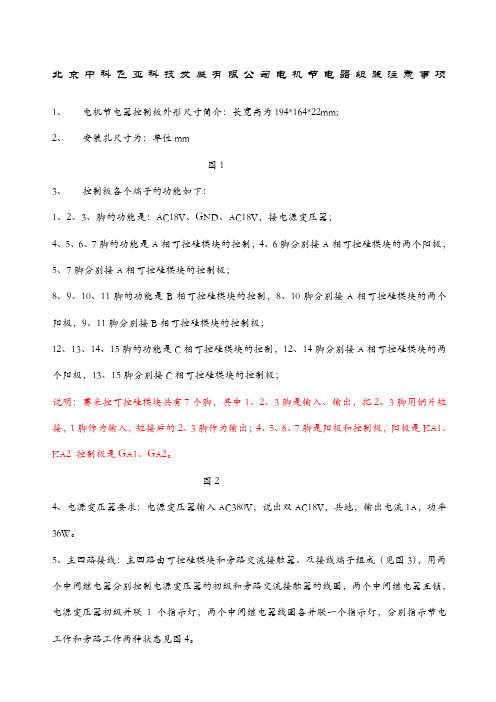
北京中科飞亚科技发展有限公司电机节电器组装注意事项1、电机节电器控制板外形尺寸简介:长宽高为194*164*22mm;2、安装孔尺寸为:单位mm图13、控制板各个端子的功能如下:1、2、3、脚的功能是:AC18V、GND、AC18V,接电源变压器;4、5、6、7脚的功能是A相可控硅模块的控制,4、6脚分别接A相可控硅模块的两个阳极,5、7脚分别接A相可控硅模块的控制极;8、9、10、11脚的功能是B相可控硅模块的控制,8、10脚分别接A相可控硅模块的两个阳极,9、11脚分别接B相可控硅模块的控制极;12、13、14、15脚的功能是C相可控硅模块的控制,12、14脚分别接A相可控硅模块的两个阳极,13、15脚分别接C相可控硅模块的控制极;说明:赛米控可控硅模块共有7个脚,其中1、2、3脚是输入、输出,把2、3脚用铜片短接,1脚作为输入,短接后的2、3脚作为输出;4、5、6、7脚是阳极和控制极,阳极是KA1、KA2 控制极是GA1、GA2。
图24、电源变压器要求:电源变压器输入AC380V,说出双AC18V,共地,输出电流1A,功率36W。
5、主回路接线:主回路由可控硅模块和旁路交流接触器、及接线端子组成(见图3),用两个中间继电器分别控制电源变压器的初级和旁路交流接触器的线圈,两个中间继电器互锁,电源变压器初级并联1个指示灯,两个中间继电器线圈各并联一个指示灯,分别指示节电工作和旁路工作两种状态见图4。
图3图4ZK500-B系列电机软启动跟踪节电器用户使用手册目录一:节电器的工作原理…………………………二:节电器的技术特性…………………………三:产品技术参数………………………………四:节电器的适用对象………………………..五:节电器的安装与调试……………………....六:质量保证……………………………………七:注意事项……………………………………八:常见问题………………………………….北京中科飞亚科技发展有限公司地址:北京市朝阳区十八里店世豪花园18号电话:010- 139 传真:010-一:节电器的工作原理交流电动机是电气化的主要动力源,也是电网中主要的秏能设备,在供电电网中约有70%的电量是被电机所消耗,据统计,约有60%以上的电机是远低于其设计负荷状态下(额定负荷的60%以下)运行的。
SJDZ操作说明

在本产品运行前请认真阅读本说明书,以避免给产品或其他设备带来损坏!SJDZ节电器使用说明书安徽三益电力技术一、简介本公司的专利技术产品稳压节电器,是针对传统节电器的缺点而设计,采纳最新高科技自耦补偿调控原理,通过稳压调控、电磁移相、电磁平稳变换等技术完美结合,大幅提高了节电效率,节电率平都可达10%-20%。
是目前最先进的高效节电器,适用于各类三相和单相用电设备。
二、用途稳压节电器,产品适用于集中操纵的照明灯光系统(如:超市、餐厅、饭馆、医院、学校、银行、展览馆、停车场、游乐场、便利商店、百货商店、办公大楼、各类工厂、广告灯箱、路灯、公路隧道等)和以三相异步电动机及单相电机为动力的用电设备(如冲压机、车床、铣床、磨床、搅拌机、输送带、造粒机、注塑机、油泵、水泵、工业缝纫机、风机、粉碎机、球磨机、制砖机、锯料机、纺织机等)。
三、型号说明SJDZ- □—□ / □单相/三相功率(KW)/电流(A)节电对象(Z照明型,T通用型,D动力型)专利产品型号四、结构原理稳压节电器踊跃提倡绿色环保理念,实现大幅提高节电成效与净化电网质量双重目标,针对目前电网实际运行参数,通过实时监测电器负载转变的情形,应用最优化操纵原理,自动操纵输出功率,操纵供给电器设备的功率为实际需要的功率,达到精准匹配。
提高电器设备的功率因数,降低线损,增大线路容量,提高系统用电效率,使电压平稳取得改善,减少电器设备附加损耗,延长电器设备的利用寿命,从而有效实现了系统综合节电。
五、要紧特点1、节电成效显著,本装置在电机空载时可将空载电流降低,使输入视在功率大大降低,专门是对可变负载的电机,平均节电率可达10%-20%。
提高电网功率因数,降低线损及变压器铜损。
2、具有降压启动功能,将起动电流操纵在额定电流的1-4倍之间,并持续可调。
可取代降压启动器,节约大量的有色金属,适用于不同工况用起动器,应用范围普遍。
减少了启动电流对电网的冲击和对电机及设备的冲击转矩,减少电机的损耗,从而降低了电机的工作温度,延长电机的利用寿命。
- 1、下载文档前请自行甄别文档内容的完整性,平台不提供额外的编辑、内容补充、找答案等附加服务。
- 2、"仅部分预览"的文档,不可在线预览部分如存在完整性等问题,可反馈申请退款(可完整预览的文档不适用该条件!)。
- 3、如文档侵犯您的权益,请联系客服反馈,我们会尽快为您处理(人工客服工作时间:9:00-18:30)。
')"#"*'+,*
!"#$%% %&%'"(
4
01010101010101010101010101010101010101010101010101010101010101 01010101010101010101010101')"#"*'+,*010101010101010101010101010101010101 01010101010101010101010101')"#"*'+,*01010101010101010101010101 01010101010101010101010101010101010101010101010101010101010101
4. 清洗时
• • • • 清扫即移动时,先')"#"*'+,* 关闭开关并隔离电源后进行. 清洗时,用柔和的干布来擦净. 用湿毛巾布来擦洗时可能会引起故障或触电. 用酒精,汽油,苯,稀释剂,洗涤剂等擦洗时,请注意其涂色被擦掉。 ')"#"*'+,*
')"#"*'+,*
')"#"*'+,*
!"#$%% %&%'"(
使用时注意事项
• 请不要在通风口周围堆积东西,以免发生堵塞. • 通电时,请不要接触电线连接部分,有触电危险. • 通电时,请不要在产品内放入金属或手, 有触电,故障及火灾的危险。 • 请不要用湿润的手操作产品. • 操作控制板时,请事先了解正确的说明书后再操作。 • 请不要把产品当作电动机或起动机来使用. • 关闭电源时,请先关闭负载的开关.(OFF) • 开启电源的(ON)时,先开启总电源开关后,再开启负荷的开关.
Advanced R&D Technology
TKELECTRIC
TAEKYUNG ELECTRIC POWER CO.,Ltd, Flections Energy Saving Technology
DELOSS 运转 MAUAL
确认负荷运转电压
表示DELOSS의 运转状态
表示故障警报状态
表示确认AUTO / MANUAL MODE 状态
2. 安全注意事项
• 负载大于产品的负载时, 节电产品有可能会被损坏. • 为了安全,产品的容量选定负载容量的120%为佳. 特别要注意的是由于相的不平衡而引起的各相的超负载. • 本产品为室内型,请注意避免高温或高湿度,直射光线多的地方,并牢固连接各处连接部分。 • 本产品应存放于儿童不能接触的地方。
!"#$%% %&%'"(
01010101010101010101010101010101010101010101010101010101010101 01010101010101010101010101')"#"*'+,*010101010101010101010101010101010101 01010101010101010101010101')"#"*'+,*01010101010101010101010101 01010101010101010101010101010101010101010101010101010101010101
Gas式 蓄电器
可变磁速节电 TRANSFORMER
POWER IN/OUT DIAGRAM
')"#"*'+,*
POWER INPUT
NEUTRAL
POWER OUTPUT
')"#"*'+,*
')"#"*'+,*
')"#"*'+,*
!"#$%% %&%'"(
6
01010101010101010101010101010101010101010101010101010101010101 01010101010101010101010101')"#"*'+,*010101010101010101010101010101010101 01010101010101010101010101')"#"*'+,*01010101010101010101010101 01010101010101010101010101010101010101010101010101010101010101
')"#"*'+,*
')"#"*'+,*
')"#"*'+,*
')"#"*'+,*
!"#$%% %&%'"(
3
01010101010101010101010101010101010101010101010101010101010101 01010101010101010101010101')"#"*'+,*010101010101010101010101010101010101 01010101010101010101010101')"#"*'+,*01010101010101010101010101 01010101010101010101010101010101010101010101010101010101010101
DELOSS的运转 PROGRAM 输入 键
')"#"*'+,*
AUTO MODEMANUAL MODE 重复
BYPASS MODEAUTO MODE 重复 按三秒以上 ')"#"*'+,* 转换为PROGRAM MODE
')"#"*'+,*
')"#"*'+,*
!"#$%% %&%'"(
7
01010101010101010101010101010101010101010101010101010101010101 01010101010101010101010101')"#"*'+,*010101010101010101010101010101010101 01010101010101010101010101')"#"*'+,*01010101010101010101010101 01010101010101010101010101010101010101010101010101010101010101
3. 使用时注意事项
• 使用之前, 请仔细阅读“使用上的注意事项”, 并正确使用。阅读之后,请妥善保管。 • 这里所提出的注意事项,是为了避免使用者以及其他人员受伤问题等的内容, 请务必遵守。 • 下面是当不遵守注意事项而错误使用时所发生的危险,损害等的内容。
')"#"*'+,*
')"#"*'+,*
5
01010101010101010101010101010101010101010101010101010101010101 01010101010101010101010101')"#"*'+,*010101010101010101010101010101010101 01010101010101010101010101')"#"*'+,*01010101010101010101010101 01010101010101010101010101010101010101010101010101010101010101
Advanced R&D Technology
TKELECTRIC
TAEKYUNG ELECTRIC POWER CO.,Ltd, Flections Energy Saving Technology
6. PROGRAM 方法
按三秒以上ENTER 键
当显示OUT 时,按 ENTER 键 显示设定电压 , 可用 - up/down 按钮来调节 : out设定负载的最佳电压的模式,设定结束后,按 ENTER 键. 显示out时,按 up button按钮. 显示tp1 ▶ 按ENTER 键 则显示所设定的tap1电压, 可用- up/down 按钮来调节button : tp1为 tap1的电压调节值. Tap1输 入时期负载电压调节为 -7 volt . Enter后, 如果显示 tp1, 按 Up 键.
Advanced R&D Technology
M
TKELECTRIC
TAEKYUNG ELECTRIC POWER CO.,Ltd, Flections Energy Saving Technology
节电装
DELOSS AVR 节电系统使用说明
')"#"*'+,*
elec.co.kr
(株)泰慶電氣産業
Advanced R&D Technology