制动器调整装置使用说明书
JF122H(JB)制动器试验台使用说明书
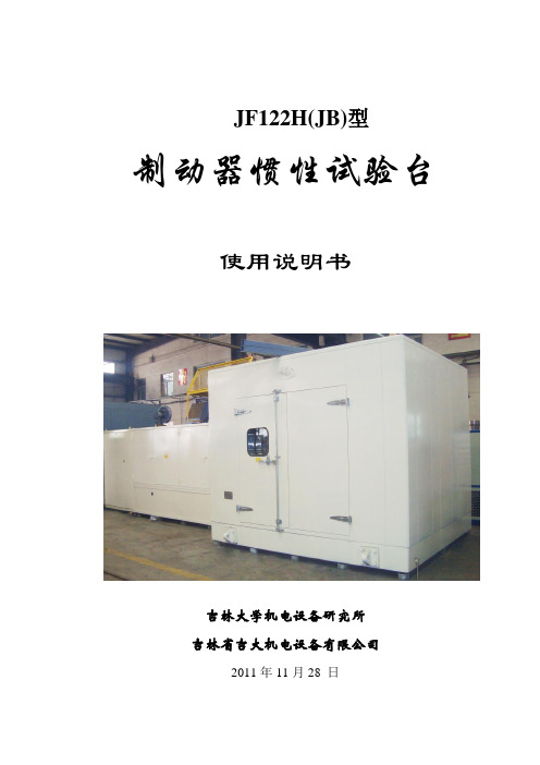
JF122H(JB)型制动器惯性试验台使用说明书吉林大学机电设备研究所吉林省吉大机电设备有限公司2011年11月28 日目录1. JF122H制动器试验台的用途及特点........ ............ . (3)2. JF122H制动器试验台的主要技术参数.............. . (4)3. JF122H制动器试验台的结构及工作原理............ . (7)4. JF122H制动器试验台的安装与调试................ .. (10)5. JF122H制动器试验台的标定及试验准备............ .. (14)6. JF122H制动器试验台的试验台的维护保养........ .. (19)7. JF122H制动器试验台的常见故障及处理方法.... .. (21)8. JF122H制动器试验台的易损外购件明细表. ............... (22)9附图1.试验机结构图2.被试制动器联结件图3.液压原理图及零件表4.气动原理图及零件表5.电气原理及接线图※本试验台的计算机,绝对不允许运行与此设备无关的软件;以免感染病毒, 影响设备的正常运行。
否则,引起一切后果自负。
1. JF122H型制动器惯性试验台用途及特点1.1用途JF122H型制动器试验台,其试验原理是根据制动副摩擦力矩与压力成正比的特性而确定的;其试验原理是目前全世界摩擦材料和汽车制造商所公认的。
JF122H型制动器试验台应用于生产质量控制和摩擦材料的开发;测试摩擦材料的摩擦系数及制动器摩擦衬片与压力,速度,温度的相关特性及耐磨损性能等;还可用于制动器的噪声测试。
适用于载重量小于3.0吨的盘式制动器及摩擦衬片及鼓式制动器及摩擦衬片。
1.2特点JF122H型制动器试验台是制动器及摩擦衬片的摩擦性能惯性试验设备。
在惯性飞轮的设置形式上,参照了德国申克公司的等比法兰固定式( 5.0kg.m2, 2.5 kg.m2, 1.25 kg.m2)和美国LINK公司的等分锥轴固定式(80.0 kg.m2, 40 kg.m2×3,20.0 kg.m2 , 10 kg.m2×2)) 设计。
高处作业电动吊篮安全装置的调试说明

高处作业电动吊篮安全装置的调试说明吊篮一般须配备制动器、行程限位、安全锁等,并必须经检验合格才能安装。
制动器主制动器1、该制动器应能使吊篮平台在100mm范围内停住,采用常闭式制动器。
2、主制动器选用闸刀式或盘式,并整体安装在提升机构上或提升电机上,制动器的各部分位置匀应便于检修和调整,并有防水保护。
辅助制动器1、辅助制动器一般应刚性安装在提升机构的机架或底座上,可用常闭式制动也可用手动机械制动,该制动器主要是使用在提升机构采用手摇驱动情况下,能使吊篮平台在100mm范围内停住,其安装位置要便于操作、检修和调整,并有防水保护。
卷扬式提升机构的卷筒若装在屋面小车上(动力装置位于屋面),也必须配备制动器,并需符合主制动器与辅助制动器的要求。
行程限位吊篮必须装上下限位开关,以防止吊篮平台上升或下降到端点超出行程的范围。
行程限位装置的安装方式须是以吊篮平台自身直接去触动。
安全锁1、吊篮上必须装有安全锁,并在吊篮平台悬挂处增设一根与提升机构上使用的相同型号的安全钢丝绳。
每根安全钢丝绳上必须有不能自动复位的安全锁。
2、安全锁应能使吊篮平台在下滑速度大于25m/min时动作,并在不超过100mm的距离内停住。
3、安全锁的动作要灵敏,工作要可靠,并需经严格的检验和试验,不合格的产品不准装配和出厂,安全锁必须在有效期内使用,超期必须由专业厂检测合格后方可使用。
安全装置的调试:1.检查悬挂装置各部位是否稳固,加强绳是否拉紧,配重是否符合比例要求,紧固件是否有松动。
2.检查电源线连接点,观察指示灯。
3.按启动按钮,检查平台是否处于水平,检查限位开关,碰撞上限位开关,平台停止。
4.检查提升器与平台的连接处。
5.检查安全钢丝绳与安全锁连接是否可靠,动作是否正常。
6.提升器:(1)使用前检查电机电磁制动装置是否正常;(2)将一载荷提升到距地面1m处,然后马上停止上升,检查吸铁制动器和电器装置;(3)操作运转时不得有异常响声、冒烟和怪味现象;(4)不能有任何异物进入箱体内;(5)在非不得已情况外,切勿拆卸提升器和任意更动机构内任何零部件;(6)检查传动机构的润滑是否良好,不允许有水或腐蚀性液体渗入机内;7.安全锁:防倾斜式安全锁,检查吊篮平台倾斜8度是否能自行锁牢。
AltraMotion SIME 制动器说明书

A l t r a M o t i o nSIME Brakes North AmericaMain characteristics :• Standard AISE N.11• DC series or shunt coils available, or coils for use with rectifier AC power• Steel base with laminated steel armatures • Self-lubricant bushings at main hinge points • Brake Shoe auto-aligning device• Aluminium brake shoes with organic linings Options :• Limit switch release control • Automatic wear compensator • Limit switch wear control•Manual release lever with or without stopDRUM BRAKESBraking torque 50 - 9000 lb.-ft.Discs Ø6" to 30"Stromag supplies SIME Brakes solutions for various industrial applica-tions to ensure highest performance and safety in motion :• Steel works: cranes, hoists and winches• Lift Bridges, dams, doors and moveable floors • Offshore tower cranes• Mining and cement applications, material handling conveyors • Nuclear cranesWe are at your disposal for any information or technical support:COMPLETE BRAKING SOLUTIONSMain characteristics :• Standard AISE N.11• Scale for torque adjustment• Automatic lining wear compensation • Brake shoe auto-aligning device • Brake lever synchronisation • Self-lubricated bushings• Galvanized steel spindles and hinges Options :• High temperature - Low temperature • Opening switch - Lining wear indicators • Steel works - Special voltages•Manual release lever with or without stopAs a complement to its drum brakes, Stromag proposes two types of drum couplings to offer a complete braking system:• PB drums & PB-C drum couplings • SP drums & SP-C drum couplings Main characteristics :• Standard DIN 15435• Flanged hub fitted with rubber bushes • Uniform distribution of loads, even in case of misalignement• Reduction of resonance effects at critical velocitySAB RANGEDRUMS & COUPLINGSBraking torque 55 - 8800 lb.-ft.Drums Ø6" to 30"Series PB-C & SP-CDrums Ø160 to 710 mmClaude AuffretWichita ClutchChristian KleinLaurent Vinogradoff Global Product Manager IP BrakesHeavy Duty Clutches & Brakes ******************************Global Technical Business Development Manager Stromag Product Specialist Brake Solutions************************** +1-800-964-3262 (toll free)******************************************************+33 608 712 315+1-940-723-3400+49 173 399 1584+33 248 807 3152P-8787-SG-A4 | BRC10166-01-A 7/19Main characteristics :• Types: TDXB-I and TDXB-II • TS or VS thrustors• Automatic lining wear compensation • Self-centering / • Opening sensor • Low maintencance Teflon bushes • Manual release lever• TS thrustors equipped with Viton seals •Symmetrical designOptions :• Sensors: Closing / Thrustor limit stroke • SIDHT: high temperature Steel Works •Custom colorBraking torque 660 - 21240 N.mDiscs Ø355 to 995 mm 3 types of discs couplingsDiscs Ø175 to 995 mmDISCS & COUPLINGSAs a complement to its disc brakes, Stromagproposes three types of disc couplings to offer a complete braking system solution:• GCS coupling is a Double Engagement Gear Coupling. • Stromag Periflex ® Shaft Coupling is a Highly-Flexible rubber / fabric tyre coupling.• SVK-SDK Coupling (picture above) is a High-ly Flexible coupling equipped with a cam ring and a lastomeric element.Main characteristics :• Spring application - Hydraulic release • Opening proving switch • Lining wear indicators• SHS: caliper mounted on a support • SHC: SH with Hydraulic Power pack •Association with disc thicknesses: 12.7 15 - 20 - 30 or 42 mmOptions :• Progressive braking system • Offshore protection• Lining temperature sensor•High temperature, iron and steel conditionsDISC BRAKESSH RANGEBraking torque 230- 458000 N.mDiscs Ø300 to 3000 mm 3 P-8787-SG-A4 | BRC10166-01-A 7/19SAB THRUSTOR DRUM BRAKESSAB Thrustor Drum Brakes are associated with different thrustors and springs for a large range of braking forces.Protected against adverse environmental effects in their respective applications, they have precision tuned safety functions.They permit easy adjustment of the braking torque with an accurate scale control following thedemands of the AISE No. 11.P-8787-SG-A4 | BRC10166-01-A 7/19100020003000400050006000700080009000S A B –6”S A B –8”S A B –10”S A B –12”S A B –13”S A B –15”S A B –16”S A B –19”S A B –23”S A B –30”SAB Thrustor Drum Brakes offer many technical advantages and options:• an automatic system of lining wear compensation • a manual release lever (option HRL)• a torque scale for easy adjustment• full lining wear indicators (option LWI)•an opening proving switch (option BRLS)•special paint or protection level (otions SPA & SPR)TS thrustors offer also a large range of options to meet requirements of every applications.HRL SPA SPECIAL PAINT SPR PROTECTION LEVEL C4TORQUE SCALE (standard)BRLS OPENING SWITCHoption COMPENSATION SYSTEM(standard)Descent Valve5 P-8787-SG-A4 | BRC10166-01-A 7/19TDXB THRUSTOR DISC BRAKESTDXB-I and TDXB-II Thrustor Disc Brakes areequipped with different thrustors and springs for a large range of braking forces.These symmetrical brakes are designed for easy installation and maintenance. Their robust construction and simple operation bring high reliability.100020003000400050006000Ø795Ø705Ø625Ø550Ø495Ø445Ø395Ø355Ø315Disc diameter (mm)TDXB-IBraking Torque (N.m)(3 types of spring)TDXB-IIBraking Torque (N.m)(3 types of spring)0500010000150002000025000Ø995Ø795Ø705Ø625Ø550Ø495Ø445Disc diameter (mm)6P-8787-SG-A4 | BRC10166-01-A 7/19TDXB-I and TDXB-II Thrustor Disc Brakes offer in standard multiple technical advantages:• an automatic system of lining wear compensation • a manual release lever• lining full wear indicators • a proximity switch for opening monitoring •a self-centering system•low maintenance Teflon bushesThey are proposed with TS thrustors; VS thrustors are optional. A large range of options allow to meet requirements of every applications.CLAMPING FORCE SETTINGMANUAL RELEASE LEVERSPRING WITH TORQUE SCALECENTERING SYSTEM PROXIMITY SWITCHESCOMPENSATION SYSTEM The manual release lever enables to:• open manually the brake by cancelling the braking force• lock the brake in open positionIt is mounted on the release rod, actuated and locked in position on the roller.Actuation on the torque setting nut enables to modify the spring compression to the requested torque value.This system balances the lining pads gap on each side of the discduring brake operation.Opening switchOptions: Closing and Stroke switches.This system adjusts the opening gap tocompensate the lining wear.Thus, it ensures a constant braking force throughout the life of the lining pads.7 P-8787-SG-A4 | BRC10166-01-A 7/19EMERGENCY HYDRAULIC BRAKESHYDRAULIC POWER PACKS - CSHCSH HPP , associated with calipers type SH or SHD, are designed in different configurations to meet the installation requirements, they enable:• Soft braking for lifting and lowering the load: adjustable and progressive application of the braking force• Full braking for boom and hoisting movements• Manual Overload Protection System for offshore cranesSH5SH9A SH15SH18B SH25SH32HPP• It is designed according to the CRT16 60.C.016 EDFGEARBOXDRUMEMERGENCY STAND-BY BRAKE ENCODER 1Speed signals9 P-8787-SG-A4 | BRC10166-01-A 7/19SOLUTION FOR EVERY APPLICATIONWhatever your requirement for safety, performance and reliability is, Stromag offers standard or fully customised braking systems solutions. Here are two examples of Stromag braking systems:OUTSTANDING SHIP LIFTStromag was chosen to supply accurate braking systems for the ship lifts of the Silin, Shatuo and Goupitan hydroelectric stations on Wujiang river in China.For each project, a huge braking system, designed to secure hoisting of the ship reservoirs (weight up to 3300 tons), to a maximum height of 79 meters, includes:• 200 to 240 hydraulic emergency brakes type SH32 (braking force: 334 kN),• 8 to 20 hydraulic service brakes type SHD5,•2 to 5 custom hydraulic power packs with electrical control and monitoring unit.HEAVY LIFT OFFSHORE CRANESModular Stromag SHD1 braking systems equip, for several leading global OEM, large mass cranes installed on offshore construction vessels which provide heavy lifting capability to support surface or sub-sea asset installation.These braking systems offer an economical braking solutions: they are factory-tested and designed to be mounted directly on the rear of 400kW motors and above.With years of extensive offshore application experience, Stromag can provide braking systems that meet various certifications including LR, ABS, and DNV-GL.P-8787-SG-A4 | BRC10166-01-A 7/19CONTROL & MONITORING SYSTEMSStromag can supply a complete braking solution for smooth, controlled and regulated braking, under all load conditions, for specific applications.Port crane braking systems require a proportional application of the brake torque. Therefore Stromag developed and supplied to various harbour crane OEM and End-User a unique system consisting of:• 2 thrustor brakes type SAB mounted on the rotation shaft of the drivers cabin of the port crane,• 1 potentiometric control foot-pedal, in addition to the ON/OFF control of the brakes, • 1 converter unit which converts the voltage variation of the potentiometric foot-pedal into a frequency variation: the braking force is applied smoothly and progressively to cancel the inertia.For a proportional braking controlled by the customer PLC, the foot-pedal can be replaced by the CRD® module. The required rate of deceleration is set on the CRD®module. In this way, the equipment deceleration is regulated by the control of the brakes torque, through the converter unit, accordingly to that rate. At the same time, speed can be monitored by the SIDEOS One module.Automatic control11P-8787-SG-A4 | BRC10166-01-A 7/19P-8787-SG-A4 | BRC10166-01-A 7/19T he Brands of Altra Motion C ouplings Ameridrives Bibby Turbofl ex www.bibbyturbo Guardian Couplings HucoLamifl ex Couplings mi Stromag TB Wood ’s Linear Systems Thomson Warner LinearGeared Cam Limit Switches StromagEngineered Bearing Assemblies Kilian Electric Clutches & Brakes Matrix Stromag Warner Electric Deltran Belted Drives TB Wood’sHeavy Duty Clutches & Brakes Twifl ex www.twi Stromag Svendborg Brakes Wichita ClutchGearing & Specialty Components Bauer Gear Motor Boston Gear Delevan Delroyd Worm Gear Nuttall GearEngine Braking Systems Jacobs Vehicle Systems Precision Motors & Automation Kollmorgen Miniature Motors Portescap Overrunning Clutches Formsprag Clutch Marland Clutch StieberNeither the accuracy nor completeness of the information contained in this publication is guaranteed by the company and may be subject to change in its sole discretion. The operating and performance characteristics of these products may vary depending on the application, installation, operating conditions and environmental factors. The company’s terms and conditions of sale can be viewed at /terms-and-conditions/sales-terms-and-conditions. These terms and conditions apply to any person who may buy, acquire or use a product referred to herein, including any person who buys from a licensed distributor of these branded products.©2019 by Stromag LLC. All rights reserved. All trademarks in this publication are the sole and exclusive property of Stromag LLC or one of its af liated companies.Stromag FacilitiesEurope GermanyHansastraße 12059425 Unna - Germany +49 (0) 23 03 102 0Clutches & Brakes, Couplings, Geared Cam Limit Switches, Discs, Wind BrakesDessauer Str. 1006844 Dessau-Roßlau - Germany +49 (0) 340 2190 0Electromagnetic Clutches & Brakes FranceAvenue de l’Europe18150 La Guerche sur L’Aubois - France +33 (0)2 48 80 72 72Disc Brakes & Drum Brakes Great BritainAmpthill RoadBedford, MK42 9RD - UK +44 (0)1234 324347Electromagnetic Clutches & Brakes, Industrial Caliper BrakesNorth America USA31 Industrial Park RoadNew Hartford, CT 06057 - USA 860-238-4783Electromagnetic Clutches & Brakes 300 Indiana Highway 212Michigan City, IN 46360 – USA 219-874-5248Couplings2800 Fisher Rd.Wichita Falls, TX 76302 - USA 940-723-3400Geared Cam Limit Switches, Industrial Caliper & Drum Brakes South AmericaBrasilAvenida João Paulo Ablas, 2970Jardim da Glória, Cotia - SP , 06711-250 - Brasil +55 (11) 4615-6300Flexible Couplings, Bearing Isolators, and Coupling GuardsAsia Pacifi c ChinaT40B -5, No. 1765 Chuan Qiao Road Pudong 201206, Shanghai - China Tel +86 21-60580600Clutches & Brakes, Electromagnetic Clutches & Brakes, Couplings, Industrial Caliper & Drum Brakes, Discs, Geared Cam Limit Switches, Wind Brakes IndiaGat No.: 448/14, Shinde Vasti, Nighoje Tal Khed, Pune- 410 501+91 2135 622100Clutches & Brakes, Electromagnetic Clutches & Brakes, Couplings, Industrial Caliper & Drum Brakes, Discs, Geared Cam Limit Switches, Wind Brakes。
西伯瑞制动器说明书 盘式 USBIII
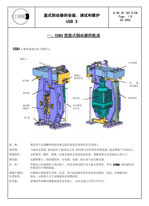
盘式制动器的安装、调试和维护USB 3B 06 20 185 E-CNPage 1/6 05.2002一、USB3型盘式制动器的组成USB3主要组成部分如下图所示:底 板: 通过四个安装螺栓将制动器安装在底部支架或者其它结构上。
制动臂: 与制动瓦连接,制动盘位于制动瓦之间。
制动臂与拉杆和杠杆板连接,通过弹簧产生制动力。
弹簧组件: 由弹簧管、螺杆、弹簧、活塞支板和力矩刻度标组成。
调整弹簧可改变制动力的大小。
推动器: 克服弹簧力,制动器松闸。
有电液、电磁、液压或气动式推动器。
拉 杆:将制动力传递到两个制动臂上。
拉杆是制动器中受力最大的部件。
所有SIBRE 制动器的拉杆都采用不锈钢制成。
摩擦片磨损: 对摩擦片磨损进行补偿。
但是,每个制动循环的补偿量是有限的。
因此,应根据实际 补偿装置 情况,由维修人员手动调整来补偿磨损量。
杠杆板: 弹簧组件和推动器都连接在杠杆板上,以此实现小行程大作用力。
杠杆板制动臂制动靴 摩擦片底 板手动释放弹 簧 调节螺母弹簧组件摩擦片 磨损补偿推动器手动释放 加长管插图 1二、从制动盘的一侧进行安装注意:运行调试之前,应拆卸掉吊环!1.拆除端盖A,调节制动瓦之间的距离至比制动盘厚度大2 mm。
2.将制动器置于底座上,滑入制动盘,拆除吊环 。
3.安装推动器,并连接安装电气、液力 或气动系统。
4.拧紧拉杆调节螺母至摩擦片靠紧制动盘 制动器自动对中。
5.调整补偿行程,见第4页。
6.利用推动器,使制动器开合数次。
7.仔细检查制动器相对于制动盘是否 对中,必要时应进行调整。
8. 制动器处于合闸位置并对中后,等力矩拧紧四个底脚螺栓。
采用8.8级或更高级螺栓, 在螺帽下装入硬质垫片 (DIN125 200HV 或 300HV )。
9.制动器允许对中误差值为:max.±0.3 mm(1')。
插图 2拉杆调节螺母端盖 A拉 杆拉杆调节螺母插图 3三、制动器调试方法1. 推动器断电(制动器合闸)。
INTORQ BFK470 弹簧加压式电磁制动器 使用说明书
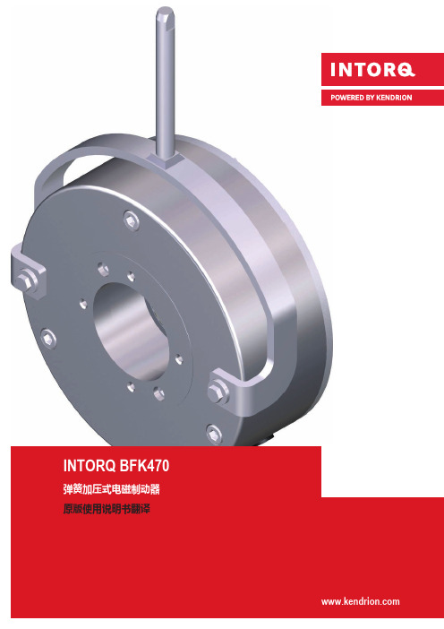
INTORQ BFK470弹簧加压式电磁制动器原版使用说明书翻译文件档案材料代号版本说明33001440 1.02012/01TD09第一版33001440 1.12012/03TD09补充技术数据33001440 1.22012/10TD09对章节“安装制动器”进行补充更新了“采用缩写”补充参数,额定数据和反应时间33001440 2.02013/05TD09更改了防护等级补充电机端盖属性的注意事项定义轴的特性,补充章节“机械安装”,章节“检查制动器”(维修及保养)补充章节“检查制动器”(维修及保养)33001440 3.02013/05TD09更新有关“分离时间”的文本33001440 3.12014/03SC全新建构,有关制动密封的说明33001440 4.02015/01SC统一电路图33001440 5.02016/07SC补充机座号为06,08,10,12的设备型号33001440 6.02017/03SC防腐蚀等级,表格变更330014407.02020/10SC 修改章节“Kendrion INTORQ弹簧加压制动器的应用领域”更新铭牌和包装贴签330014408.02021/02SC更名为Kendrion INTORQ. 更新第4.7章法律法规责任¾文件中所含的各种信息、数据和说明,只是排印时的最新内容。
因此不能将本文件中所含的各种规定、插图和说明作为标准,而对现供产品提出权利要求。
¾对由于以下原因产生的受损情况及/或工作故障,我们恕不承担责任:–使用不恰当–对本产品擅自进行改造–使用本产品失当,或对本产品处理不当–操作错误–不注意遵守技术资料中的指引质量保证提示有关质保条件的信息请参阅Kendrion INTORQ GmbH。
的销售及供应条款。
¾当发现本产品存在缺陷或错误时,应立即通知Kendrion INTORQ公司。
¾否则,将导致所有保修责任和保修要求无效。
汽车碟式刹车分泵调整回位工具使用说明
汽车碟式刹车分泵调整回位工具使用说明一、工具介绍汽车碟式刹车分泵调整回位工具是一种专门用于调整汽车碟式刹车分泵回位的工具。
它由一个手柄和一个可调节的螺丝钉组成。
手柄用于握持,螺丝钉用于调整刹车分泵的回位力度。
二、使用步骤1. 准备工作:首先,确保车辆停在平坦且安全的位置,切断点火开关,拉紧手刹,确保车辆不会滑动。
同时,准备好需要使用的汽车碟式刹车分泵调整回位工具。
2. 定位工具:根据车辆的具体型号和刹车系统的位置,找到刹车分泵的位置。
通常刹车分泵位于发动机舱内,靠近驾驶员侧。
确保可以方便地触及到刹车分泵。
3. 插入工具:将汽车碟式刹车分泵调整回位工具的螺丝钉插入刹车分泵的调整孔中。
要注意,螺丝钉需要与孔内的凹槽相吻合,以确保插入正确。
4. 调整回位力度:握住工具的手柄,顺时针或逆时针旋转螺丝钉,使刹车分泵的回位力度适合实际需要。
要根据实际情况进行调整,避免回位力度过大或过小,以确保刹车分泵的正常工作。
5. 测试刹车:在完成调整后,可以进行简单的刹车测试。
要确保刹车踏板的回位灵敏度和刹车效果符合要求。
如果发现异常情况,应立即停止操作,并检查是否有其他问题存在。
三、注意事项1. 在调整刹车分泵回位力度时,要谨慎操作,避免过度调整或不当操作造成损坏。
2. 在使用工具时,要注意保持手柄的稳定握持,以避免工具脱落或滑动造成伤害。
3. 如果不确定如何正确使用该工具或调整刹车分泵回位力度,建议寻求专业技术人员的帮助或咨询。
结论:汽车碟式刹车分泵调整回位工具是一种简单而实用的工具,它可以帮助我们调整刹车分泵的回位力度,确保刹车系统的正常工作。
在使用工具时,要注意安全操作,并遵循正确的步骤进行调整。
如有任何不确定或需要帮助,建议咨询专业技术人员。
通过正确使用该工具,我们可以更好地维护和保养汽车的刹车系统,确保行驶安全。
地铁列车紧急制动器使用说明书

地铁列车紧急制动器使用说明书一、前言地铁列车紧急制动器是一项重要的安全设备,在紧急情况下起到保障乘客安全的作用。
为了正确使用这一装置,本说明书将详细介绍紧急制动器的使用方法和操作要点。
二、紧急制动器的作用紧急制动器是地铁列车上的一种安全措施,它能够在紧急情况下快速制动列车,以确保乘客和车辆的安全。
紧急制动器的使用可以有效减少事故风险,保护乘客的生命和财产安全。
三、紧急制动器的使用方法1. 寻找制动器位置首先,在紧急情况下,要迅速找到紧急制动器的位置。
紧急制动器通常位于列车的司机室和乘客车厢的出口,有明显的标识。
2. 拉动制动器手柄当发生紧急情况时,紧急制动器的手柄需要被牢牢地拉动。
手柄一般位于司机室的控制台或乘客车厢的墙壁上。
用力拉动手柄直到其完全固定为止。
3. 确认制动效果在拉动紧急制动器手柄后,要观察列车的制动效果。
列车应迅速减速并停下来。
如果列车没有明显减速或停下来的迹象,应重新检查制动器手柄的牢固程度,并重新执行拉动动作。
4. 通知乘客和相关人员在拉动紧急制动器之后,需要立即通知乘客和列车工作人员。
可以通过列车内的广播系统或手动通知方式向乘客传达相关信息,确保他们采取适当的安全措施。
四、紧急制动器使用的注意事项1. 紧急制动器只能在紧急情况下使用,不得滥用或误用。
违反规定使用紧急制动器可能导致不必要的危险和影响列车正常运行。
2. 使用紧急制动器时要保持冷静,并且力量要适度。
过度用力可能会损坏制动器设备,减弱制动效果。
3. 在使用紧急制动器后,应及时向相关工作人员报告,以便他们能够快速采取适当措施处理紧急情况。
4. 不得任意损坏、更改或拆卸紧急制动器设备。
如果发现紧急制动器存在异常,应及时汇报相关人员进行维修和更换。
五、总结紧急制动器是地铁列车上保障乘客安全的重要设备,正确使用紧急制动器可以在紧急情况下快速制动列车,并保障乘客的安全。
使用紧急制动器时,要明确手柄的位置,用力拉动并观察制动效果。
电力液压块式制动器说明及调整标准
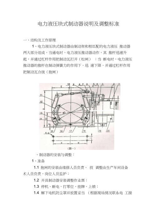
电力液压块式制动器说明及调整标准一、结构及工作原理1、电力液压块式制动器由制动架和相匹配的电力液压推动器两大部分组成,当通电时,电力液压推动器动作,其推杆迅速升起,并通过杠杆作用把制动瓦打开(松闸);当断电时,电力液压推动器的推杆在制动弹簧力的作用下,迅速下降,并通过杠杆作用把制动瓦合拢(抱闸)、制动器的安装与调整:1、准备1.1 抱闸的安装由维修人员负责,技调整由生产车间设备术人员负责,岗位人员监护;1.2 开具制动器安装调整作业票;1.3 停机、断电、打零位、挂牌、上锁;1.4 解下电机防尘罩并放置妥当(根据现场情况联系电工接拆电)2、安装2.1 安装前的检查:2.1.1 检查制动器在运输或储存过程中是否有损坏或缺件。
2.1.2 检查制动器表面是否清洁,若有油污或其他赃物,应彻底清除干净。
2.2 安装:2.2.1 根据制动器在主机的安装位置,确定出制动器的维修、调整空间较大或较方便的一侧。
如果瓦块随位调整装置13 和退距均等装置16 不在维修空间一侧时,可将其卸下装在同侧2.2.2 纵装:首先旋转弹簧拉杆6,使制动弹簧力达到最小值,然后转动拉杆10 撑开两制动臂,再将制动器套装在制动轮上。
2.2.3 横装:当制动轮已安装在电机或其他机件之间时,首先卸下螺栓14 背面的螺母,使其与退距均等装置16 脱离,然后打出销轴15 ,将制动臂11 向上掀起,从侧面装到制动轮上,安装好以后再将以上卸掉的零件重新装上。
2.2.4 安装后,应对制动器的各个性能进行检验。
3、制动器调整:3.1 推动器工作行程的调整:首先将弹簧力释放到最小值,然后旋转拉杆10 ,使制动器处于闭合状态,继续旋转,这时推动器推杆慢慢升起,当升起高度H 达到规定尺寸(一般10-15mm )时,即完成调整。
随着闸皮的磨损,H 值逐渐减小,当减到最小值H min (一般5mm )时,需及时按以上方法重新调整,否则失去制动作用。
3.2 瓦块随位的调整:在制动器处于抱闸状态时,旋转瓦块随位调整装置13 中的螺栓,使其顶端与制动瓦筋板轻轻接触,并锁紧螺母。
- 1、下载文档前请自行甄别文档内容的完整性,平台不提供额外的编辑、内容补充、找答案等附加服务。
- 2、"仅部分预览"的文档,不可在线预览部分如存在完整性等问题,可反馈申请退款(可完整预览的文档不适用该条件!)。
- 3、如文档侵犯您的权益,请联系客服反馈,我们会尽快为您处理(人工客服工作时间:9:00-18:30)。
制动器调整装置使用说明书
1、调试前的准备
(1)关断电梯主电源,拆除曳引机抱闸接线端子所有外接线缆;
(2)按信号名将本装置线缆分别连接至控制柜79、00、接地排及曳引机抱闸接线端子;
(3)接通电梯主电源,确认79、00向本装置提供DC125V电压。
2、差值模式
(1)将STATUS开关拨至“STATUS1”位置,并将清零开关向“CLR”位置拨动一次以进入本模
式;
(2)将BS开关拨至“LEFT”位置,打开左抱闸,数码管显示为左抱闸打开时间;
(3)将BS开关拨至“RIGHT”位置,打开右抱闸,数码管显示为右抱闸打开时间;
(4)将BS开关拨至中间位置,数码管显示为左侧减去右侧的差值时间;
(5)完成上述操作后将清零开关拨向“CLR”位置,则装置恢复到准备状态;
注意
(1)本说明中抱闸打开时间指抱闸得电至微动开关动作之间的历时;
(2)本装置所显示的时间为有符号十进制,单位为毫秒;
(3)差值模式下,如果数码管显示左右两侧抱闸打开的差值时间在70ms以内,说明抱
闸触点动作已满足同步性要求。
(4)差值模式下,每次动作后应停顿一段时间,以便抱闸内的电磁力完全释放,该等待
时间的确认方法为同一侧相邻两次测试值相差不超过2毫秒。
(例:第一次使用该
装置打开左侧抱闸,打开时间显示为280ms,等待数秒以后,再次使用该装置打开
左侧抱闸,打开时间应显示为280±2ms。
如果显示的打开时间超出280±2ms范围,则应等待更长时间。
)
3、间隙调节模式
(1)将STATUS开关拨至“STATUS2”位置,并将清零开关向“CLR”位置拨动一次以进入本模
式;
(2)将BS开关拨至“LEFT”位置,全压打开左抱闸,持续120秒后自动切断电源输出;
(3)将BS开关拨至“RIGHT”位置,全压打开右抱闸,持续120秒后自动切断电源输出。
4、故障代码列表
5、其他注意事项
(1)本说明中抱闸左右方向按曳引机相关说明;
(2)本说明未尽内容按照各梯种安装、维护说明书。