Ev2+PDG-SD型操作说明书
爱莫尔电源PDG23G0045TFFL产品说明书

Eaton PDG23G0045TFFLEaton Power Defense molded case circuit breaker, Globally Rated, Frame 2, Three Pole, 45A, 35kA/480V, T-M (Fxd-Fxd) TU, Standard Terminals Load Only (PDG2X3T100)Eaton Power Defense molded case circuit breakerPDG23G0045TFFL 78667991149588.9 mm 152.4 mm 104.6 mm 1.82 kg Eaton Selling Policy 25-000, one (1) year from the date of installation of theProduct or eighteen (18) months from thedate of shipment of the Product,whichever occurs first.RoHS Compliant CCC MarkedCSAIEC 60947-2UL 489Product NameCatalog Number UPCProduct Length/Depth Product Height Product Width Product Weight WarrantyCompliancesCertifications35 kAIC at 480 Vac260045 AThree-pole600 VPD2 Global30 kAIC Icu/ 22.5 kAIC Ics/ 63 kAIC Icm @440V (IEC)18 kAIC @600V (UL/CSA)35 kAIC @480V (UL)10 kAIC Icu @250 Vdc65 kAIC @240V (UL)10 kAIC Icu @125 Vdc55 kAIC Icu/ 55 kAIC Ics/ 121 kAIC Icm @240V (IEC)20 kAIC Icu/ 15/13 kAIC Ics/ 42 kAIC Icm @525V South Africa (IEC)25 kAIC Icu/ 20 kAIC Ics/ 52.5 kAIC Icm @480V Brazil (IEC) 36 kAIC Icu/ 36 kAIC Ics/ 75.6 kAIC Icm @380-415V (IEC)8 kAIC Icu/ 4 kAIC Ics/ 16.8 kAIC Icm @690V (IEC) ThermomagneticClass AComplete breakerStandard Terminals Load Only600 Vac Eaton Power Defense PDG23G0045TFFL 3D drawingConsulting application guide - molded case circuit breakersPower Defense molded case circuit breaker selection posterPower Defense brochurePower Defense technical selling bookletPower Defense molded case circuit breakers - Frame 2 product aidMolded case circuit breakers catalogPower Defense Declaration concerning California’s Proposition 65PDG2 CB reportPDG4 CCC certificationPDG4 CB reportEU Declaration of Conformity - Power Defense molded case circuit breakersPower Defense Frame 2 terminal kit - PDG2X3(2)(4)TA225RF instructions - IL012245EN H01Power Defense Frame 2 handle mech direct rotary handle instructions - IL012134ENPower Defense Frame 2 handle mech variable depth rotary handle instructions - IL012136ENPower Defense Frame 2 shunt trip UVR instructions - IL012130EN Power Defense Frame 2 clamp terminal (steel), 20A, 3 pole instructions - IL012246EN H03Power Defense Frame 2 tunnel terminal (aluminum), 150A, 3 pole instructions - IL012238EN H03Power Defense Frame 2 global terminal shield, 3 pole - IL012330EN Power Defense Frame 2 locking devices and handle block instructions - IL012149ENPower Defense Frame 2 multi wire connector kit -PDG2X3(2)(4)TA2253W instructions - IL012243EN H01Power Defense Frame 2 box terminal (steel), 100A, 3 pole instructions - IL012234EN H03Power Defense Frame 2 box terminal (aluminum), 225A, 3 poleInterrupt ratingFrameRated operation voltage (Ue) at AC - max Amperage RatingNumber of polesVoltage rating - maxCircuit breaker typeInterrupt rating rangeSwitch off techniqueClassCircuit breaker frame typeTerminalsVoltage rating 3D CAD drawing package Application notes BrochuresCatalogsCertification reports Installation instructionsT-M (Fxd-Fxd) TU instructions - IL012235EN H03Power Defense Frame 2 tunnel terminal (aluminum), 100A, 3 pole instructions - IL012237EN H03Power Defense Frame 2 terminal kit - PDG2X3(2)(4)TA150RF instructions - IL012244EN H01Power Defense Frame 2 tunnel terminal (aluminum), 50A, 3 pole instructions - IL012236EN H03Power Defense Frame 1 IEC and Frame 2 Rotary Mechanism with NFPA Handle Attachment Instructions (IL012260EN).pdfPower Defense Frame 2 tunnel terminal kits - PDG2X1TA225K instructions- IL012239EN H01Power Defense Frame 2/3/4/5/6 voltage neutral sensor module wiring instructions – IL012316ENPower Defense Frame 1-2-3-4 IP door barrier assembly instructions -IL012278ENPower Defense Frame 2 screw terminal_end cap kit, 225A, 3 pole instructions - IL012258EN H01Power Defense Frame 2 Direct Rotary Handle Assy With Interlock Version Instructions (IL012138EN).pdfPower Defense Frame 2 multi wire connector kit -PDG2X3(2)(4)TA2256W instructions - IL012242EN H01Power Defense Frame 2 PDG2 and PDC(E)9 breaker instructions -IL012106ENPower Defense Frame 2 TMTU Aux, Alarm, ST and UVR Animated Instructions.rhPower Defense Frame 2 withTMTU, Shunt Trip_UVR Animated Instructions.rhPower Defense Frame 2 Bell Alarm with PXR Animated Instructions.pdf.rh Power Defense Frame 2 Handle Mech Variable Depth Rotary Handle Animated Instructions.rhPower Defense Frame 2 Locking Devices and Handle Block Animated Instructions.pdf.rhPower Defense Frame 3 Variable Depth Rotary Handle Mechanism Installation How-To VideoPower Defense Frame 2 Direct Rotary Handle Mechanism Installation How-To VideoPower Defense Frame 2 Aux, Alarm, Shunt Trip, and UVR How-To Video Power Defense Frame 2 Variable Depth Rotary Handle Mechanism Installation How-To VideoPower Defense molded case circuit breakersTrip TypeInstallation videosMultimediaEaton Corporation plc Eaton House30 Pembroke Road Dublin 4, Ireland © 2023 Eaton. All Rights Reserved. Eaton is a registered trademark.All other trademarks areproperty of their respectiveowners./socialmediaPower Defense Frame 5 Trip Unit How-To Video Power Defense Frame 6 Trip Unit How-To Video Eaton Power Defense for superior arc flash safety Power Defense Breakers Eaton Specification Sheet - PDG23G0045TFFL Power Defense time current curve Frame 2 - PD2Molded case and low-voltage power circuit breaker health Making a better machineSingle and double break MCCB performance revisited Intelligent circuit protection yields space savings Safer by design: arc energy reduction techniques Molded case and low-voltage breaker healthSpecifications and datasheetsTime/current curvesWhite papers。
电子气栅驱动器EPCE 2系列说明书

Electric cylinder units EPCE2d I nternet: /catalogue/...Subject to change – 2023/04Electric cylinder units EPCEKey featuresAt a glancePlug and work with the Simplified Motion SeriesThe simplicity of pneumatics is now combined for the first time with the advantages of electric automation thanks to the Simplified Motion Series.These integrated drives are the perfect solution for all users who are looking for an electric alternative for very simple movement and positioning tasks between two mechanical end positions, but don't want the commissioning process for traditional electric drive systems that can often be quite complex. There is no need for any software since operation is simply based on the "plug and work" principle. Digital I/O (DIO) and IO-Link are always automatically included – a product with two types of control as standard.IntegratedEasyStandardisedConnectedThe integrated electronics in the drive are at the heart of the Simplified Motion Series.For commissioning, simply set all rel-evant parameters directly on the drive:• Speed and force• Reference end position and cushioning• Manual operationElectrical connection via M12 plug design• Power (4-pin): power supply for the motor• Logic (8-pin): control signal, sensor signal and power for the integrated electronicsUse of extended functions possible via IO-Link:• Remote configuration of motion parameters• Copy and backup function for transferring parameters• Read function for extended p rocess parameters• Freely definable intermediate position• Firmware updateThe functions of the Simplified Motion Series Basic profile for movement between two end positions: Extended motion profile for simplified press-fitting and clamping functions: v v• • Proximity switches are required in order to implement any intermediate positions.• With the intermediate position that can be freely configured via IO-Link, movements can be stopped at a freely defined point between the end positions, without the need for proximity switches or external stops32023/04 – Subject to change d I nternet: /catalogue/...Electric cylinder units EPCEKey featuresAt a glance• Without external servo drive: all the necessary electronic components are combined in the integrated drive • Two control options integrated as standard: digital I/O and IO-Link• Complete solution for simple movements between mechanical end positions• Simplified commissioning: all parameters can be manually set directly on the drive • No special expertise required for commissioning• Minimal zero stroke and extremely compact design make this product the perfect choice for applications where space is at a premium• Innovative interpretation of toothed belt technology for maximum dynamic response and minimal positioning times • Ideal for fast movement in sorting, distribution and testing applicationsThe products in the Simplified Motion Series Electric cylinder unit EPCE Electric cylinder unit EPCSElectric cylinder unit with parallelmotor mounting EPCSMini slide unit EGSS-BS-KFMini slide unit with parallel motor mounting EGSS-BS-KFSpindle axis unit ELGS-BS-KFSpindle axis unit with parallel motor mounting ELGS-BS-KFToothed belt axis unit ELGS-TB-KF Toothed belt axis unit ELGE Rotary drive unit ERMSOther variants with 3 or 4 piston rods available.Electric cylinder units EPCEPeripherals overviewCover variantsStandard Multimount, front Multimount, rear Multimount, both endsFor the variants with multimount cover (EPCE-TB-...-MF / -MB / -MD), lateral female threads with centring diameter and through-holes are also available. Mounting optionsWith standard cover variantAt the side via profile mounting On the end face via threadWith multimount coverOn the end face via thread At the side/underneath via thread Via through-holesCable outlet directionStandard[B] Rear[L] Left[R] RightControl elements[1] Pushbutton actuators for parameterisation and control4d I nternet: /catalogue/...Subject to change – 2023/0452023/04 – Subject to change d I nternet: /catalogue/...Electric cylinder units EPCEPeripherals overviewRightLeftTopRearFrontElectric cylinder units EPCEType codes6d I nternet: /catalogue/...Subject to change – 2023/0472023/04 – Subject to change d I nternet: /catalogue/...Electric cylinder units EPCEDatasheet-N- Size 45, 60-T-Stroke length 5 … 80 mm1)Adjustable in increments of 10%2)Unchangeable parameterElectric cylinder units EPCEDatasheet1) At max. feed force8d I nternet: /catalogue/...Subject to change – 2023/0492023/04 – Subject to change d I nternet: /catalogue/...Electric cylinder units EPCEDatasheet1)With cover variant EPCE-...-MF10d I nternet: /catalogue/...Subject to change – 2023/04Electric cylinder units EPCEDatasheetMaterials Sectional viewPin allocationPower supplyLogic interfacePlugPlug1324Maximum permissible loads on the piston rodIf there are two or more forces and torques simultaneously acting on the piston rod, the following equations must be satisfied:F 1/M 1 = dynamic value F 2/M 2 = maximum valueff vv =|FF yy 1|FF yy2+|FF zz1|FF zz2+|MM yy1|MM yy2+|MM zz1|MM zz2≤1 |MMMMMMMM | ≤ MMMMMMMM mmmmmmmm mmmm|FFFF FFFF | ≤ FFFFFFFF mmmmmmmm mmmm Maximum permissible lateral forces Fy max and Fz max on the piston rod as a function of projection ll [mm]F [N ]20406080100120110100EPCE-TB-45EPCE-TB-45-M...EPCE-TB-60EPCE-TB-60-M...Piston rod deflection f as a function of projection Al [mm]f [m m ]204060801001200.250.50.7511.251.51.7522.252.5EPCE-TB-45EPCE-TB-60DatasheetSizing example Application data:• Payload: 8 kg• Mounting position: horizontal • Stroke: 60 mm• Max. permissible positioning time: 0.5 s (one direction)Step 1: Selecting the smallest possible size from the table a page 12Step 2: Selecting the max. speed level v for payload mStep 3: Reading off the min. positioning time t for stroke lv m [k g ]10v t [s ]1.6l = 10 mm l = 20 mm l = 30 mm l = 40 mm l = 50 mm l = 60 mm l = 80 mma Max. speed level for payload: level 8a Min. positioning time for 60 mm at level 8: 0.3 sResultThe application can be implemented using EPCE-TB-60-60. A minimum positioning time (one direction) of 0.3 s is achieved. Longer positioning times can be selected at any time using a lower speed level.Mass m as a function of speed level v Horizontal Vertical EPCE-45EPCE-45v m [k g ]123456789100.511.522.533.544.55v m [k g ]123456789100.250.50.7511.251.51.7522.252.5EPCE-60EPCE-60v m [k g ]12345678910012345678910v m [k g ]123456789100.511.522.533.544.55H- -NoteThe lines represent the maximum values. The lower speed levels can be set at any time.DatasheetPositioning time t as a function of speed level v and stroke l EPCE-45EPCE-60v t [s ]1234567891000.20.40.60.811.21.4v t [s ]123456789100.20.40.60.811.21.41.6l = 10 mm l = 20 mm l = 30 mm l = 40mm l = 50 mml = 10 mm l = 20 mm l = 30 mm l = 40 mm l = 50 mm l = 60 mm l = 80 mmSpeed v as a function of speed level vv v [m /s ]1234567891000.10.20.30.40.50.60.7EPCE-TB-45EPCE-TB-60Feed force F as a function of force level F1F1F [N ]12345678910020406080100120140160EPCE-TB-45EPCE-TB-60H--NoteSpanner flat ß2 can be aligned either way.Datasheet-NoteH-For size 60, the through-holes cannot be used with the following combinations:• Through-hole at the front: not in combination with stroke 5 or 10 mm and motor mounting variant "Standard" (at front)• Through-hole at the rear: not in combination with motor mounting variant "Rear"Datasheet[1]At least one piston rod must be selected.[2]For size 45 with stroke 5 mm or 10 mm and cover variant -MF or -MD, not in combination with cable outlet direction "Standard".[3]For size 45 and cover variant -MB or -MD, not in combination with cable outlet direction "Rear"H--NoteFor size 60, the through-holes cannot be used with the following combinations:• Through-hole at the front: not in combination with stroke 5 or 10 mm andmotor mounting variant "Standard" (at front)• Through-hole at the rear: not in combination with motor mounting variant"Rear"AccessoriesProfile mounting EAHF-L2-...-P-S• For mounting the cylinder on the side of the profile Material:Anodised wrought aluminium alloyRoHS-compliant212023/04 – Subject to change d I nternet: /catalogue/...Electric cylinder units EPCEAccessoriesProfile mounting EAHF-L2-...-P Material:Anodised wrought aluminium alloy RoHS-compliant• For mounting the cylinder on the side of the profile.The profile mounting can be attached to the mounting surface using the drilled hole in the centreElectric cylinder units EPCEAccessories1)Packaging unit22d I nternet: /catalogue/...Subject to change – 2023/04232023/04 – Subject to change d I nternet: /catalogue/...Electric cylinder units EPCEAccessoriesFesto - Your Partner in AutomationConnect with us/socialmedia 1Festo Inc.2Festo Pneumatic 3Festo Corporation 4Regional Service Center 5300 Explorer DriveMississauga, ON L4W 5G4CanadaAv. Ceylán 3,Col. Tequesquináhuac 54020 Tlalnepantla, Estado de México1377 Motor Parkway Suite 310Islandia, NY 117497777 Columbia Road Mason, OH 45040Festo Customer Interaction CenterTel:187****3786Fax:187****3786Email:*****************************Multinational Contact Center 01 800 337 8669***********************Festo Customer Interaction Center180****3786180****3786*****************************S u b j e c t t o c h a n g e。
IEV2系列智能阀门用户手册

IEV2系列智能电动阀门用户手册北京五洲创业科技有限公司目录一、产品概述二、功能介绍1、通信功能2、智能控制功能3、防卡死功能4、宽范围供电电压5、防锈防渗漏阀体设计三、性能参数1、阀门尺寸2、阀门外形尺寸表四、机械尺寸五、型号说明IEV2智能电动阀门安装调试手册一、安装指南1、阀门安装2、电源线连接3、通信线连接二、阀门指令1、指令说明2、寄存器说明3、IEV2系列智能电动阀门的操作指令表4、阀门设置流程一、产品概述IEV2系列智能电动阀门,为您提供其它电动阀门不具有且最实用的四大功能:通信功能:提供提供RS-485接口,支持Modbus协议,可方便地与具有RS-485、Modbus通信接口的PLC、DCS、计算机等上位机及传输设备对接。
智能控制功能:可通过RS-485接口编程,编程后可在无人值守、无上位机的情况下自动运行。
防卡死功能:流体中杂质较多时,可大幅度降低维修次数。
宽范围输入电压:DC 9~35V的宽范围输入电压,可有效抵御电压波动和线路压降造成的影响。
二、功能介绍1、通信功能IEV2系列智能电动阀门,提供RS-485接口,支持Modbus协议(ASCII模式)。
通信方式:半双工。
通信速率:1200、2400、4800、9600b/s。
保护电流:50mA。
2、智能控制功能IEV2系列智能电动阀有三种工作模式,即:实时模式、星期模式、节假日模式。
实时模式在实时模式下,上位机可实时对IEV系列智能电动阀进行操作,在实时模式下IEV2系列智能电动阀可执行的控制命令有:1)开阀、关阀、阀门开度调整。
2)设置工作模式。
3)设置工作模式数据。
4)设置通信速率。
5)上报阀门开度。
6)上报阀门工作状态。
7)与上位机校对时间。
8)上报身份识别码。
星期模式星期模式必须通过上位机预先编程方可实现,编程完成后可在无上位机的情况下自动运行。
其运行方式是:将一天最多分成8个时段,每个时段的阀门开度不同,星期一至星期五按同一规律运行。
变形模量Ev2的检测应用

整理课件
16
应力—沉降量曲线方程的系数是将测试值按最小二 乘法计算得到的。用于计算系数的方程式为:
n
n
n
a0.na1.ia2.i2sii1来自i1i1n
n
n
n
a a a s . . 2 . 3 .
0
i1
i
2
i
ii
i 1
i 1
i 1
i 1
n
n
n
n
a a a s . 2. 3 . 4 . 2
变形模量Ev2的检测应用
整理课件
1
Ev2的基本概念
变形模量Ev2测试试验是平板载荷试验的一 种,利用30 cm 的圆形承载板和加载装置 ,对测试点进行第一次加载和卸载,然后 进行第二次加载,通过计算测得的应力和 相对应的位移形成的应力-位移曲线,得出 相应的Ev2和Ev2 /Ev1值。 变形模量Ev2是反映荷载作用下土体抵抗变 形能力的刚度参数。
a1 a2 1max
式中
Evi —— 变形模量(MPa);
r —— 承载板半径(mm);
1 max —— 第一次加载最大应力(MPa); a1 —— 一次项系数(mm/ MPa); a2 —— 二次项系数(mm/ MPa2)。
整理课件
18
变形模量Ev2检测示例
• 本检测示例中Ev2测试仪测桥测量臂为杠杆式,杠杆比 hP:hM﹦2.0。
的增量逐级加载,达到最大荷载为0. 5 MPa 或沉 降量达到5 mm 时所对应的应力后,再进行卸载。 • ( 5) 按最大荷载的50%、25%、0 三级进行卸载。 • ( 6) 卸载后,再次以0. 08 MPa 的增量逐级加载到第 一次所加荷载的倒数第二级。
上海精派汽车充电器SDD使用说明书
上海精派汽车充电器SDD使用说明书1、电动车充电器说明书有一条看不懂,帮忙解释一下意思是先插电动车上的插头,然后再插220伏插头,这样充电器先自检,有个时间段,所以要停十几秒钟!2、智能二段式电动车充电器的使用方法一、确定交流电与充电器输入电压是否相符。
二、确定充电器输出电压与电池额定电压是否相符。
三、先插充电器与电池盒相连的插头,后插交流电源插头,充电完成后,先拔交流电源插头。
四、充电指示灯显示红色时表示正常充电,充电完成,充电指示灯由红色变为绿色。
五、充电器用于室内,应注意防潮湿,严禁摔碰,建设不要把充电器放在电动车的后备箱中,以防止震动、颠簸。
充电时严禁覆盖,应放在通风、散热的地方,否则会影响充电器的使用寿命及充电状态,损伤电池。
3、电动汽车常用的充电方法有哪些电动汽车充电操作步骤?电动汽车常用的充电方法有两种,一种是用家里的220伏或者说30伏进行交流变直流充电。
另一种是在高速服务站或者专门的充电站,用上千伏的直流电直接充电。
具体的操作步骤,以家用的充电为例。
从后备箱取出充电器后,将充电器的一端连接到车身的充电口上,另一端接入家用的220伏插头上,此时就可以看到指示灯点亮,说明连接正常,大概到10个小时之后,可完成充电。
望采纳谢谢4、汽车电瓶充电器怎么使用?充电需要20小时,比如12V60Ah充电方式:采用恒压限流方式进行充电,恒压14.V限流15A充电16小时,再以3A恒流充电4小时,共20小时。
电瓶充满电的可根据以下现象来判断:1)蓄电池内产生大量气泡,既出现“沸腾”现象;2)端电压上升至最大值且两小时内不再上升;3)电解液上升至最高位,且两小时内不再上升。
车载充电器是指常规通过汽车电瓶(轿车12V, 卡车24V)供电的车载充电器,大量使用在各种便携式、手持式设备的锂电池充电领域。
5、电动车正确充电方法?电动车的充电问题一直以来都是用户最关心的问题之一。
充电方式不正确有可能损伤电池和电机,甚至有可能造成安全隐患。
变形模量Ev2的检测应用
测量仪器
• 变形模量Ev2测试仪器应包括承载板、反力装置、 加载装置、荷载量测装置及沉降量测装置。
沉降测量装置:
• 沉降量测装置由测桥和测表组成。测桥的测量臂可采用杠 杆式(见图1)或垂直抽拉式(见图2)。测量臂应有足够 的刚度。
图1 杠杆式测量臂 1—触点 2—承载板 3—千斤顶 4—加长杆件 5—反力装置 6—沉降量测表
7—支撑架 8—杠杆支点 9—测量臂 10—支撑座
图2 垂直抽拉式测量臂 1—触点 2—承载板 3—千斤顶 4—加长杆件 5—反力装置
6—沉降量测表 7—支撑架 8—垂直支架 9—支撑座
试验方法
变形模量Ev2的检测应用
Ev2的基本概念
变形模量Ev2测试试验是平板载荷试验的 一种,利用30 cm 的圆形承载板和加载装 置,对测试点进行第一次加载和卸载,然 后进行第二次加载,通过计算测得的应力 和相对应的位移形成的应力-位移曲线,得 出相应的Ev2和Ev2 /Ev1值。 变形模量Ev2是反映荷载作用下土体抵抗 变形能力的刚度参数。
应力
沉降量S(mm )
变形模量Ev2的计算:
• 第一次加载和第二次加载所得到的应力—沉降量曲线,可 用下式表达:
s = a0 + a1·σ + a2·σ²
• 式中 σ——承载板下应力(MPa); s ——承载板中心沉降量(mm); a0——常数项(mm);
a1——一次项系数(mm/ MPa); a2——二次项系数(mm/ MPa2)。
1
a2 1max
E E v2 v1
结语
通过公式计算的Ev2值反映了路基的承 载力指标,路基压实质量越好,Ev2值 越大;反之Ev2值越小。变形模量Ev2指 标比地基系数K30更科学、更合理,目 前客运专线路基压实质量的控制已采用 了Ev2指标。
电磁阀ESV-S D系列使用说明书
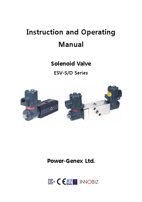
Instruction and OperatingManualSolenoid ValveESV-S/D SeriesPower-Genex Ltd.1. Introduction1.1General InformationThis instruction and operating manual contains important notices the user should observe for a personal safety as well as for prevention against damage to property. Notices concerning a personal safety are highlighted by a safety alert symbol ().1.2General Safety InstructionsThis product was delivered out from the factory without any safety problems after a strict quality management process. In order to maintain this status and ensure a safe operation of this product, please be sure to read all safety instructions carefully described in this manual and observe safety information and symbols without exception.1.3 Correct Usage① This product can be used only for purposes specified in these instructions. If they are notdefinitely stated in these instructions, the user is fully responsible for all changes and retrofits to this product.② This product is the electrostatic sensitive device that may be seriously damaged by voltagesundetectable to a human. These kinds of voltages occur as soon as a electronic component or an assembly is touched by a person who is not grounded against a static electricity.Damage to a electronic component as a result of overvoltage cannot usually be detected immediately. It may become apparent after a long period of operation. Therefore, please make sure to avoid electrostatic charge.1.4 Range and Responsibilities of Personnel① Qualified personnel should be trained, instructed or authorized in operating and maintainingproducts and systems according to the safety regulations for electrical circuits, high voltages and hazardous atmosphere.② For explosion proof products, they should be trained, instructed or authorized in carrying outwork on electrical circuits for hazardous systems.③ They should be trained or instructed in maintenance and use of proper safety equipmentaccording to the safety instructions.④ They should have a good experience to identify risks and avoid potential hazards whenworking with these products and systems.1.5 Transport and StorageMake sure that damages during delivery are prevented through proper packaging.Products and replacement parts should be returned in their original packaging. If the original packaging is no longer available, please ensure that they should be packaged to provide sufficient protection against transport.2. SpecificationsSingle CoilDual CoilESV-SESV-SSESV-DESV-DSOperating Air pressure 1.5 ~ 10 bar Supply Air Pressure (Max.) 15 bar Operating Voltage : CurrentAC 220V : 17mA AC 110V : 55mA DC 24V : 138mAVoltage Tolerance ±10%Explosion proof class Exd IIC T6 (KC-certified)Operating Ambient Temp.-20 ~ +60℃Flow Capacity(Cv) 0.9Mounting Configuration NAMUR or screw interfacePneumatic Connections PT 1/4 or NPT 1/4 Electrical Connections G 1/2, NPT 1/2 or M20Coil Insulation GradeClass F or H Duty Cycle 100%Material (body)Aluminum 316SS Aluminum 316SS Weight0.9Kg1.9Kg1.4Kg2.5Kg3. Part Numbering System (order code)Model No.ESV - x xX XCoil(s)Single coilS Dual coilsDMaterialAluminum . 316SS SOperating VoltageAC 220 A220 AC 110 A110 DC 24D24Connections (Pneumatic -Electrical)Rc 1/4 - G1/2 P NPT 1/4 - NPT 1/2N4. Principle of Operation1) If power is on a magnetic force is created around coils.2) The armature core (10) is moved to and blocks the armature vent body (20). 3) A supply air pushes a spool through the orifice body (3) and vents out from Port 4. 4) If a voltage is not supplied, a magnetic force around coils disappears.5) A supply air from the orifice body (3) is blocked by a spring between the armature seat (18) and the armature core (10).6) A supply air pushes the spool from the bottom through an air line at the center, and air remaining in the orifice body (3) vents out from the vent body (20). 7) Eventually, a supply air vents out from Port 2 when power is off.5. Manual SwitchThe ESV solenoid valve can be operated by this switch manually while air is supplied. - Ininitial setting “0” : the ESV solenoid valve works with a power voltage. - Manual operation “1” : Port 4 is open regardless of a power voltage.When power is off and the manual switch is positioned to “0”, Port 2 becomes open. When the manual switch is postioned to “1”, Port 4 becomes open.“0”“1”Note that the manual switch is not active when power is off.<Power On / Activated><Power Off / Normal>6. InstallationAs the ESV solenoid valve is designed for NAMUR mounting pattern, it can be mounted directly onto the pneumatic actuator without an additional piping. Also, as it has Rc 1/4 or NPT 1/4threads inside of the connections as standard, the screw interface is available.<Single coil type><Dual coils type>7. Electrical ConnectionsThe ESV solenoid valve head can be rotated by 90° to the right or to the left for an optimal mounting as shown below.① Supply the rated voltage and current stated on this manual. Otherwise, it may cause a serious damage or malfunctions.② Observe all explosion proof regulations required in the area.. ③Earth internally and externally before using.8. Spare PartsNo. Description No.Description1 Valve Body 15 Orifice Body Bolt2 Valve Body Cover 16 Valve Body Cover Bolt3 Orifice Body 17 Armature Seat Ring4 Coil Box Body 18 Armature Seat Bolt5 Coil Box Cover 19 Armature Seat Tube6 Terminal Box Cover 20 Armature Vent Body7 Terminal Box 21 Solenoid Coil Bobbin8 Valve Spool 22 Solenoid Coil9 Orifice 23 Solenoid Coil Cover10 Armature Core 25 Terminal Box Bolt11 Stop Pin 26 Ground Bolt12 Stop Pin Spring 27 Air Vent13 Auto-Manual Switch14 Auto-Manual Switch Stop Pin9. Dimensions 9.1 ESV-S9.2 ESV-DPower-Genex Ltd. 99, Eunbong-ro, Namdong-gu, Incheon 405-849 Korea Tel : +82-32-812-6644Fax : +82-32-812-6645Website : E-mail : ********************Subject to change without prior notice。
变形模量Ev2的检测应用

测量仪器
• 变形模量Ev2测试仪器应包括承载板、反力装置、 加载装置、荷载量测装置及沉降量测装置。
沉降测量装置:
• 沉降量测装置由测桥和测表组成。测桥的测量臂可采用杠 杆式(见图1)或垂直抽拉式(见图2)。测量臂应有足够 的刚度。
资料整理与计算
承载板中心沉降量s计算公式:
S
SM
hp hM
式中
• S ——承载板中心沉降量(mm); • S M ——沉降量测表读数(mm);
• hP/hM——杠杆比(在1:1至2:1范围内选择)。
• 根据试验结果绘制应力—沉降量曲线(见图6.0.2),应 力—沉降量曲线上应用箭头标明受力方向。
应力
沉降量S(mm)
变形模量Ev2的计算:
• 第一次加载和第二次加载所得到的应力—沉降量曲线,可 用下式表达:
s = a0 + a1·σ + a2·σ²
• 式中 σ——承载板下应力(MPa); s ——承载板中心沉降量(mm); a0——常数项(mm);
a1——一次项系数(mm/ MPa); a2——二次项系数(mm/ MPa2)。
Evi 1.5r 1
a1 a21max
式中
Evi —— 变形模量(MPa); r —— 承载板半径(mm);
1max —— 第一次加载最大应力(MPa);
a1 —— 一次项系数(mm/ MPa); a2 —— 二次项系数(mm/ MPa2)。
变形模量Ev2检测示例
• 本检测示例中Ev2测试仪测桥测量臂为杠杆式,杠杆比 hP:hM﹦2.0。
应力—沉降量曲线方程的系数是将测试值按最小二 乘法计算得到的。用于计算系数的方程式为:
- 1、下载文档前请自行甄别文档内容的完整性,平台不提供额外的编辑、内容补充、找答案等附加服务。
- 2、"仅部分预览"的文档,不可在线预览部分如存在完整性等问题,可反馈申请退款(可完整预览的文档不适用该条件!)。
- 3、如文档侵犯您的权益,请联系客服反馈,我们会尽快为您处理(人工客服工作时间:9:00-18:30)。
HMP PDG-SD型Ev2静态变形模量测试仪(平板载荷试验仪)操作使用维护手册德国HMP马格德堡试验仪器制造有限责任公司本产品依据下列标准开发:德国工业标准DIN 18 134:2001-09地基、试验过程和试验仪器平板载荷试验目录 (1)概况使用说明…………………………………………2.标志说明 (2)安全说明 (2)法律说明 (2)平板载荷试验仪技术参数 (3)基本构造 (4)平板载荷试验仪的组成部分 (4)测试测试准备 (6)承载装置的安装 (6)三点支撑架的安装 (6)仪器的连接 (6)测试过程 (7)测试开始 (7)测试结束 (8)测试值读取/打印测试数据 (9)AP 1300小型打印机 (9)读取/打印测试数据 (12)传输测试数据到PC (13)删除测试数据 (13)时钟/日期时间/日期调整 (14)设备维护电子测定仪……………………………………..15.电池充电 (15)标定 (15)服务热线 (15)附录1平板载荷试验仪的组件 (16)行业标准中对于Ev2测试的操作要点 (17)仪器的使用说明以下关于HMP PDG-SD型Ev2静态变形模量测试仪(平板载荷试验仪)的使用能帮助用户更简单、更迅速地了解和使用本产品。
在使用PDG-SD型Ev2静态变形模量测试仪(平板载荷试验仪)前,请确认已详细阅读本使用说明。
标志说明在本公司出品的PDG-SD型Ev2静态变形模量测试仪(平板载荷试验仪)使用说明书中,采用以下警告的提示标志:本标志为使用提示标志,提醒用户注意使用说明中对使用仪器时的要求。
安全说明法律证明Ev2静态变形模量测试仪(平板载荷试验仪)符合德国工商职业总会事故安全保护条例及其他有关的安全标准(VBG/UVV)。
Ev2静态变形模量测试仪(平板载荷试验仪)的仪器安装和使用符合德国工业标准《DIN 18 134 平板载荷试验》的相关规定。
Ev2静态变形模量测试仪(平板载荷试验仪)符合欧盟合格证书中一致性规程规定的基本安全要求。
技术参数加载装置1X液压泵1X压力缸(最大压力100KN,冲程150mm)1X高压软管(长度2m)6X可插拔式压力缸接长杆(1X40mm,1X90mm,1X120mm,1X160mm,2X60mm)1X磁性球接头上压板承载板1X带手柄和盒式水准器的承载板直径:300mm厚度:25mm位移测试装置1X三点支撑架(带有可伸缩、可旋转杠杆臂,底座可调节) 尺寸:2320X570X420mm(长X宽X高)重量:12.5Kg压力测试电子式50KN力传感器,包括压力部件和连接装置位移测试数显电子测量表,量程25mm,精度0.01mm,保护等级IP 42自动数据采集、分析、处理装置测试头用于采集力和位移测试数据,并准确无误地数字化传输到电子测定仪电子测定仪采集力和位移测试数据,并自动分析处理,可存储200组数据。
电子测定仪包含:-可通过舒适的用户界面用电子测定仪进行测试数据的采集、存储和分析处理。
-液晶显示屏,尺寸60X30mm-电池,工作时间12小时,可使用电源或车用充电器充电。
小型打印机,可现场打印测试数据和应力-位移曲线。
铝制仪器箱尺寸:460X340X210mm重量:8Kg基本构造Ev2静态变形模量测试仪(平板载荷试验仪)组成部分承载装置1磁性球接头上压板2可插拔式压力缸接长杆3压力缸4压力部件5压力盒6测量筒7带盒式水准器的承载板8液压泵图示2位移测试装置1测量臂2支撑横梁3测量基准架4测试头5数显电子测量表6盒式水平器图示3数显电子测量表1数显电子测量表2数显电子测量表连接线图示4 测试箱 1 电子测定仪 2 电子压力表3 数显电子测量表4 测试头5 压力部件6 打印机 图示5 电子测定仪1 LCD 显示屏2 功能键“Power ”∙电源(红色);“Select ” 选择(黄色);“Enter ” 确认(绿色) 3 打印机接口 4 测试电缆312图示5承载装置的安装测试点按照德国工业标准DIN 18 134中的要求准备。
将承载板放置在测试点上。
⇨测量筒的开口起导向作用,用于连接测量臂。
将压力盒放在承载板的轴径上,压力部件放在压力盒上。
压力缸放在压力部件上。
将磁性球接头上压板靠近加载机动车。
⇨用可插拔式压力缸接长杆调整高度。
三点支撑架的安装(见附件1)将支撑横梁(2)安装在测量基准梁(3)上,并调整高度。
取出测量臂(1)将其连接到测量基准梁上(3)上,并用两只螺栓将其固定。
测量臂的另一端按照指示标记连接到测量筒,并借助盒式水准器(6)将整个三点支撑架调成水平。
将数显电子测量表(5)安装在测量基准梁(3)上的测量表接口处度固定。
仪器的连接测试头的定位将测试头(4)安装在支撑横梁(2)上(采用磁性固定方式)。
压力盒的连接将压力盒的连接线插入测试头(4)上标有“Force”的插口中。
数显电子测量表(位移测量表)的连接先将数显电子测量表连线与数显电子测量表接好。
再将连线另一端接到测试头(4)上标有“Distance”的插口中。
电子测定仪的连接用测试头(4)的连线将电子测定仪与测试头(4)连接。
PDG-SD 型Ev2静态变形模量测试仪(平板载荷试验仪)测试过程的理论依据为德国工业标准DIN 18 134。
测试开始按∙键打开电子测定仪。
⇨ 主菜单显示在屏幕上,如左图。
“HMP PDG-SD XXXX ”:厂家、型号、设备编号 “Measuring ”: 测试菜单 “Memory ”: 存储菜单 “Accu#.#V ”: 工作电压⇨ 闪烁的光标▌提示其所对应的菜单目前处于激活状态下。
当电子测定仪工作电压在7.2V-7.9V 范围内时,可以正常使用。
当电池工作电压低于7.2V 时,“Accu charge ”(充电)提示将显示在测定仪显示屏上(详细情况请参见说明书第15页的说明)。
按 键确认进入“Measuring ”(测试)菜单。
⇨ 显示屏上出现测试菜单,如左图: n :当前测试的序列编号 #.####MN/m 2: 应力 #.##mm : 位移这些值由测试仪器所承受的测试载荷决定。
⇨ 当存储空间占满后,测试无法继续进行。
此时显示屏将显示提示,如左图。
按 键可以返回主菜单。
如需继续进行测试,可以将已存储的测试数据转移(例如:传输数据到PC 保存或用打印机打印出来),然后删除所有数据,就能提供新的存储空间。
测试值1预加载、卸载后,按 键将显示值清零。
⇨ 屏幕上显示0.0000MN/m 表示力的测试值,0.000mm 表示位移测试值。
这些值作为第一级测试值将被存储。
通过消除可能出现的零点误差,测试可以开始。
数显电子测量表上的显示值不受零调节的影响。
请参见德国工业标准DIN 18 134中关于测试级数的设定值的要求来进行测试。
测试的进行通过液压泵加载到设定值。
⇨ 应力和位移的测试值会显示在显示屏上。
当前测试的序列编号(n)和当前测试级数的编号(m)也会在显示屏上显示出来。
在达到规定的荷载持续持续时间后,用 采集测试值。
⇨ 按下 Key 键后,测试值将不再变化,固定在显示屏上。
⇨ “Store ?”(是否存储?)的提示将出现在显示屏的上方。
用☜键可以在“Store ?”(是否存储?)和“Delete ?”(删除)模式间转换。
按 键可以对当前(固定)的测试值进行“Store?”(存储)或“Delete ?”(删除)的操作确认。
⇨ 当前的测试值在显示屏上有显示。
测试过程中其他设定值的测试按照以上的相同步骤进行即可。
测试结束当所有要求的测试都完成后,测试过程便可结束。
在最后的测试值存储完毕后,按☜键退出测试。
⇨ 显示屏上显示菜单,如左图。
按☜键可以选择返回最后的测试值,继续进行测试。
按 键确认,结束测试过程。
结果显示当确认退出测试后,测试程序将终止。
⇨ Ev1值、Ev2值和Ev2/Ev1比值将显示在显示屏上。
⇨ “Print ?”(是否打印?)的提示显示在显示屏上。
按☜键可以在“Prinr ?”(打印)和“Back ?”(返回)模式间转换。
按 键确认“Print ?”(打印)模式。
⇨ 打印机自动启动,打印机LED 指示灯亮。
⇨ 包含应力-位移曲线在内的当前测试序列的数据将由小型打印机打印出来。
⇨ 显示屏幕显示主菜单。
按 键确认“Back ?”模式。
⇨ 显示屏显示主菜单。
读取/打印测试数据通过“Memory”(存储)菜单中的“Read/Print”(读取/打印)模式,存储器中的测试序列和数据可以显示在显示屏上,也可以打印出来。
AP 1300小型打印机HMP PDG-SD型静态变形模量测试仪配备有一个AP 1300小型打印机。
Power supply打印机可以单独使用充电电池作为电源,打印机内置有1.8A镍/多发氢电池作为电源,可方便地在各工作地点间移动使用。
安全性电池可以采用仪器所提供的充电器充电。
充电器可连接100-240V/50-60HZ的电源,或用专用转接线连接12-24V的汽车电池来进行充电。
仪器中所提供的专用转接线放置在手提箱中、电子测定仪下方位置。
AP 1300小型打印机出厂前已连接到位并且电池已经充电。
电池充电将充电器连接到打印机的“电源”接口。
将充电器连接到电源。
所提供的充电器通过LED 灯的不同颜色来区别两种不同的操作提示状态: 红灯(闪烁)-提示处于与电池正确连接的测试阶段(大致为10秒); -提示电池未能正确连接正极负; -提示电池损坏或型号错误; -提示在按下放电键后的放电过程。
红灯(长亮)-提示电池正在充电的过程。
绿灯(长亮)-提示电池已充电完毕。
打印机充电状态查询打印机充电状态可按以下方法查询: 按∙键打开电子测定仪的电源。
连续按☜键三次。
⇨ “Srate of charge ”(充电状态)菜单显示出来。
按 键确认“State of charge ”(充电状态)菜单。
⇨ 稍等就会在显示屏上显示当前的打印机电压。
打印机工作电压不能低于6.3V 。
按☜键或 键均可退出“State of charge ”(充电状态)菜单。
打印机面板功能1 送纸 单行送纸:-按下送纸键,然后松开。
多行送纸-按下送纸键不放,直到达到需要的纸条的长度。
2 LED 指示灯 显示准备打印信号LED 灯灭-打印机处于省电模式。
LED 灯(长亮) -打印机已激活。
LED 绿灯(闪烁) -打印机充电。
LED 红灯(闪烁) -电池电压太低。
3 纸仓开关AP 1300小型打印机具有自动打开或关闭功能。
不需要人工进行打开或关闭。
安装纸卷向前方推纸仓开关,直到打印机盖打开(1)。
将新的纸卷拉出约数厘米的纸头,将纸卷放入纸仓,使纸头从下方穿出。
关闭打印机盖。
按下送纸键观察纸卷是否正确送出。
用打印机的切断器可以快速撕下伸出的打印纸。