ROCO火车模型 Z21中文用户指南-v0.1
pyrosim说明书翻译(精品)

pyrosim说明书翻译(精品)pyrosim说明书翻译(精品)6.4.1 停止和再启动一个重要的MISC 参数叫RESTART。
建立一个CHID.STOP 的文件在目录下。
重新开始, RESTART=.TRUE.需要添加到MISC行中。
第二章:PyroSim基础PyroSim界面pyrosim为您建立火灾模型提供了四个编辑器:3D模式,2D模式,导航模式和记录模式。
这些都可以显示您现在的模型。
当添加了、移除了、或在一个模式中选择了一个物体,其它的模式也同时反映出这些变化。
下面简要介绍这几种模式。
导航视图:在这个视图下列出了模型中许多重要的记录。
它可以使您将您的模型中几何体组成一个组,例如组成房间或者沙发。
在这个模式下,定位和修改档案比较快捷。
3D视图:这个视图中以3D形式显示了您的火灾模型。
您可以以不同的视角查看您的模型。
您也可以控制模型的外观细节,如平滑阴影、纹理和物体轮廓线,也可以改变几何特征。
2D视图:在这个视图中您可以快速的画出几何体,例如墙和家具。
您可以从三个视角查看您的模型,也可以执行许多有用的几何操作。
档案视图:这个模式给出了为本次模拟产生的FDS输入文件的预览。
它提供了加入不经过pyrosim处理而直接输入FDS的自己的代码的方式。
导航视图导航视图是在Pyrosim主窗口左部的树状视图。
下图是使用这个视图的一个例子。
当你右键点击这个视图中的一个项目时,将显示Pyrosim可以在这个项目上执行的功能。
重新排列物体时,点选一个物体,然后拖转至新的位置。
在导航视图中使用菜单3D视图运用3D视图可以迅速得到模型的视觉外观。
导航选项包括标准CAD控制模式,Smokeview型的控制,游戏型的控制查看模型。
3D轨道导航点击激活3D轨道导航。
这个模式的控制方式与许多CAD程序的控制模式相似。
后,左键点击模型并移动鼠标,模型将会随着您点选的点选转。
旋转3D模型:点击点选(或按住ALT键)并竖向移动鼠标。
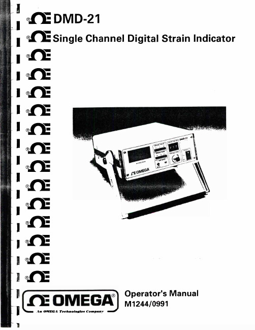
Omega DMD-21单通道数字裂断指示器操作手册说明书
FOR WAR RANTY RETURNS, please have the FOR NON-WARRANTY REPAIRS OR CALIBRATIC
following information available BEFORE contacting consult OMEGA for current repair/calibration charg
A Precision Two-State
Zero Adjustment is provided ensuring ease of zero setting together with ease of re-setting for subsequent tests. An analog
output is provided on the rear panci for connection to a
to be maybe
enecasoiluyntearcecdomimondat,ulsde,
but gage factors by setting the
outside this range
gage factor to 2.00 and
calculating the strain (see Section 4).
by such brench.
Every precaution for accuracy has been taken in the preparation of this manual, however, OMEC
ENGINEERING, INC. neither assumes responsibility for any omissions or errors that may appear nor assunliabilii for any damages that result from the use of the products in accordance with the information contain in the manuill.
北欧轨道 NTC59021 产品使用指南说明书

USER'S MANUALCAUTIONRead all precautions and instruc-tions in this manual before using this equipment. Keep this manual for future reference.Serial Number DecalQUESTIONS?As a manufacturer, we are com-mitted to providing complete customer satisfaction. If you have questions, or if there are missing parts, we will guarantee satisfaction through direct assis-tance from our factory.TO AVOID DELAYS, PLEASE CALL DIRECT TO OUR TOLL-FREE CUSTOMER HOT LINE.The trained technicians on our customer hot line will provide immediate assistance, free of charge to you.CUSTOMER HOT LINE:1-888-825-2588Mon.–Fri., 6 a.m.–6 p.m. MSTModel No. NTC59021Serial No.Visit our website at new products, prizes,fitness tips, and much more!Patent PendingNordicTrack is a registered trademark of ICON Health & Fitness, Inc.Congratulations for selecting the new NordicTrack®SL700exercise cycle. Cycling is one of the most effective exercises for increasing cardiovascular fit-ness, building endurance, and toning the entire body. The NordicTrack®SL700 offers an impressive array of features designed to let you enjoy this healthful exercise in the comfort and privacy of your home. For your benefit, read this manual carefully before you use the exercise cycle.If you have questions after reading this manual, call our Customer Service Department toll-free at 1-888-825-2588, Monday through Friday, 6 a.m. until 6 p.m. Mountain Time (excluding holidays). To help us assist you, mention the product model number and serial number when calling. The model number is NTC59021. The serial number can be found on a decal attached to the exer-cise cycle (see the front cover of this manual for the location of the decal).Before reading further, please familiarize yourself with the parts that are labeled in the drawing below.FEATURES OF THE CONSOLEThe advanced console offers a selection of features designed to make your workouts more enjoyable and effective. When the manual mode of the console is selected, the resistance of the exercise cycle can be changed with a touch of a button. As you exercise, the console will provide continuous exercise feedback. You can even measure your heart rate using the hand-grip pulse sensor. Note: For information about an optional chest pulse sensor, see page 19.The console also offers six resistance and pace pro-grams. Each program automatically changes the resis-tance of the exercise cycle and prompts you to increase or decrease your pace as it guides you through an effective workout.In addition, the console features two heart rate pro-grams that automatically change the resistance of the exercise cycle and prompt you to vary your pace to keep your heart rate near a target heart rate as you exercise.The console also features new interactive technology. Having technology is like having a personal trainer in your home. Using the included audio cable, you can connect the exercise cycle to your home stereo, portable stereo, or computer and play special CD programs (CD’s are available sep-arately). CD programs automatically control the resistance of the exercise cycle and prompt you to vary your pace as a personal trainer coaches you through every step of your workout. High-energy music provides added motivation. Each CD features two pro-grams designed by certified personal trainers.In addition, you can connect the exercise cycle to your VCR and TV and play video programs (video-cassettes are available separately).Video programs offer the same benefits as CD programs, and add the excitement of working out with a class and an instructor.With the exercise cycle connected to your computer, you can also go to our Web site at and access programs directly from the internet. Explore for details.To purchase CD’s and videocassettes, call toll-free 1-800-735-0768.HOW TO CONNECT YOUR CD PLAYER, VCR,OR COMPUTERTo use CD’s , the exercise cycle must be connected to your portable CD player, portable stereo,home stereo, or computer with CD player. See pages 15 and 16 for connecting instructions. To use videocassettes , the exercise cycle must be connected to your VCR. See page 17 for connecting instructions.To use programs directly from our Web site , the exercise cycle must be connected to your home computer. See page 16 for connecting instruc-tions.HOW TO CONNECT YOUR PORTABLE CD PLAYER Note: If your CD player has separate LINE OUT and PHONES jacks, see instruction A below. If your CD player has only one jack, see instruction B.A.Plug one end of the audio cable into the jack beneath the console. Plug the other end of the cable into the LINE OUT jack on your CD player.Plug your headphones into the PHONES jack.B.Plug one end of the audio cable into the jack beneath the console. Plug the other end of the cable into a 1/8” Y-adapter (available at electronics stores). Plug the Y-adapter into the PHONES jack on your CD player. Plug your headphones into the other side of the Y-adapter.HOW TO CONNECT YOUR PORTABLE STEREO Note: If your stereo has an RCA-type AUDIO OUT jack, see instruction A below. If your stereo has a 1/8” LINE OUT jack, see instruction B. If yourstereo has only a PHONES jack, see instruction C.A.Plug one end of the audio cable into the jackbeneath the console. Plug the other end of the cable into the adapter. Plug the adapter into an AUDIO OUT jack on your stereo.B.Plug one end of the audio cable into the jack beneath the console. Plug the other end of the cable into the LINE OUT jack on your stereo. Do not use the adapter.C.Plug one end of the audio cable into the jack beneath the console. Plug the other end of the cable into a 1/8” Y-adapter (available at electronics stores). Plug the Y-adapter into the PHONES jack on your stereo. Plug your headphones into the other side of the Y-adapter.HOW TO CONNECT YOUR HOME STEREONote: If your stereo has an unused LINE OUT jack, see instruction A below. If the LINE OUT jack is being used, see instruction B.A.Plug one end of the audio cable into the jackbeneath the console. Plug the other end of thecable into the adapter. Plug the adapter into theLINE OUT jack on your stereo.B.Plug one end of the audio cable into the jackbeneath the console. Plug the other end of thecable into the adapter. Plug the adapter into anRCA Y-adapter (available at electronics stores).Next, remove the wire that is currently plugged into the LINE OUT jack on your stereo and plug thewire into the unused side of the Y-adapter. Plug the Y-adapter into the LINE OUT jack on your stereo. HOW TO CONNECT YOUR COMPUTERNote: If your computer has a 1/8” LINE OUT jack, see instruction A. If your computer has only a PHONES jack, see instruction B.A.Plug one end of the audio cable into the jackbeneath the console. Plug the other end of thecable into the LINE OUT jack on your computer. B.Plug one end of the audio cable into the jackbeneath the console. Plug the other end of thecable into a 1/8” Y-adapter (available at electronics stores). Plug the Y-adapter into the PHONES jack on your computer. Plug your headphones or speak-ers into the other side of the Y-adapter.HOW TO USE PROGRAMS DIRECTLY FROM OUR WEB SITEOur Web site at allows you to play audio and video programs directly from the internet. To use programs from our Web site, the exer-cise cycle must be connected to your home computer.See HOW TO CONNECT YOUR COMPUTER on page 16. In addition, you must have an internet con-nection and an internet service provider. A list of spe-cific system requirements will be found on our Web site.Follow the steps below to use a program from our Web site.Go to your computer and start an internet connection.Start your Web browser, if necessary, and go to our Web site at .Follow the desired links on our Web site to select a program.Read and follow the on-line instructions for using a program.Follow the on-line instructions to start the program.When you start the program, an on-screen count-down will begin.Return to the exercise cycle and begin pedaling.When the on-screen countdown ends, the pro-gram will begin. The program will function in almost the same way as a resistance and pace program (see step 3 on page 12). However, an electronic “chirping” sound will alert you when the resistance setting and/or the pace setting is about to change.Monitor your progress with the two displays.See step 4 on page 10.Measure your heart rate if desired.hands-free 98765431 1 Frame2 1 Upright3 1 Handlebar4 1 Console5 1 Handlebar Cover6 2 Pulse Sensor7 1 Seat Bracket8 1Seat Post9 1 Seat10 1 Seat Knob 11 1 Seat Carriage 12 2 Seat Bushing 13 1 Front Stabilizer Cover 14 1 Rear Stabilizer Cover 15 1Front Stabilizer 16 1 Rear Stabilizer 17 2 Wheel 18 1 Right Pedal Strap 19 4 Leveling Foot 20 1 Seat Post Knob 21 1 Right Pedal 22 1 Left Pedal 23 1 Right Crank Arm 24 1 Left Crank Arm 25 1 Left Pedal Strap 26 1 Left Side Shield 27 1 Right Side Shield 28 1 Snap Ring 29 1 Pulley 30 1 Magnet31 1 Crank Assembly 32 1 Thrust Washer 33 2 Crank Bearing34 1 Flywheel/Generator 35 1 “C” Magnet36 1 Resistance Cable 37 1 Spring38 1 Resistance Motor39 1 Idler Arm40 1 Control Board 41 1 Control Bracket 42 1 Upper Wire Harness 43 1 Lower Wire Harness 44 1 Adjustment Bracket 45 1 Clamp46 1 Reed Switch/Wire 47 1 Drive Belt48 1 Flywheel Axle 49 1 Shoulder Screw 50 2 Flange Screw 514Stand-off 52 1 M10 Nylon Locknut 53 2 Bolt Set 54 12 M8 x 40mm Button Screw 55 18 M8 Split Washer 56 8 M4 x 38mm Screw 57 12 M4 x 16mm Screw 58 3 5/16” x 12mm Button Screw 59 4 M8 x 25mm Patch Screw 60 4 M5 x 12mm Screw 61 2Handgrip 62 1 M10 Washer 63 7 M8 Nylon Locknut 64 3 M6 Nut 65 13 M4 x 25mm Screw 66 1 Eyebolt 67 1 Idler Bolt 68 1 M10 x 22mm Tapered Bolt 692M5 Nut 701M6 x 38mm Bolt 714M5 Washer 724M6 Nylon Locknut 734M6 x 18mm Bolt # 1 Allen Wrench # 1 User’s ManualNote: “#” indicates a non-illustrated part. Specifications are subject to change without notice. See the back coverof this manual for information about ordering replacement parts.Key No.Qty.DescriptionKey No.Qty.DescriptionPART LIST—Model No. NTC59021R0503AEXPLODED DRAWING—Model No. NTC59021R0503APart No. 195806 R0503A Printed in China ©2003 ICON Health & Fitness, Inc.。
罗托克中文说明书

在电池报警图标显示时,应立即更换电池。(参见第 61页)
执行器大约10分钟检查一次电池状态。更换电池后,电池报警图标将继续显示10分钟,直到下一次检测到电池的状态为良好,图标才会消失。
设定方式 - 口令18
新口令18
检查方式18
程序路径分支-19
分支点(Cr)
7.8执行器的显示19
设定 / 检查方式
返回阀位指示19
8设定-
初级设定功能20
初级设定功能目录21
9设定-
二级设定功能30
二级设定功能目录30
10维护和故障排除61
帮助显示63
IrDA诊断和组态68
11重量和尺寸70
二进制、十六进制、十进制71
及挡圈的安全。
3.加工驱动轴套,使其适合于阀
杆,允许提升式阀杆的螺纹有间隙,并确保阳螺纹不受损坏。
重新组装
1.清除驱动轴套上的铁屑,确保螺纹及轴承挡圈的清洁和润滑。
2.将轴承装入驱动轴套,确保其与轴台吻合。
3.将轴承挡圈固定在驱动上,并用平头螺钉上紧。
4.将驱动轴套重新安装在执行器底座铸件上,并确保驱动轴套上的槽与空心输出轴上的键吻合。
如果执行器符合特殊的危险气体区域认证,则无需对其进行检查和维修。无论在任何情况下,都不应对执行器进行任何改造,因为这将使已经获得的认证失效。
在危险区域内,禁止用导电、导热体接触执行器,除非进行经特殊允许的工作,否则应切断电源,将执行器卸下并移到非危险区域进行维修或保养。
只有经过培训的、有经验的、能够胜任的人员才可被允许安装、维护和修理这些执行器,并应按照手册中的介绍来进行工作。用户和设备操作人员应根据1974年版的健康与安全条例以及与他们工作有关的规定条款来熟悉他们的职责。
PIKO火车模型中文数码控制说明书

目录快速上手1. 按照第8页“连接与操作”章节所描述的方法,将电源适配器和控制器Digi 1连接好。
2. 火车头在出厂时已经分配了硬件地址。
这个硬件地址和火车头在PIKO Digi 遥控器上使用的传输通道一起印刷在火车头底部的标签上。
3. 将火车头放在轨道,并记住它的硬件地址和传输通道(可以在火车头底部的标签上查到)。
然后根据指定的传输通道(A、B、C、D之一),在遥控器上按下相应的键就可以开动火车头了。
接着你就可以通过“+”、“-”按钮来控制火车头的速度。
如果在火车头行驶时,你按下了“<-”或“->”键,那么它会紧急刹车,然后变换方向行驶。
我们建议你多练习几次以掌握控制火车头速度的技巧。
4. 如果你想在轨道上放置另一个(与先前火车头的硬件地址不同的)火车头,那么按照以下步骤做。
(1)让第一个火车头停下,然后把第二个放到铁轨上。
(2)在遥控器上按下第二个火车头传输通道号后,你就可以控制它了。
(3)如果你想让两个火车头都跑起来,那么只要按照步骤3所说的,通过选择对应的传输通道先选定一个火车头,调整它的行驶速度和方向,然后再选定另一个,调整它的行驶速度和方向就行了。
以上就是数字控制的全部内容。
多练习几次你就能掌握它了。
5.如果在同时操纵两个火车头时发生紧急情况,比如两个火车头快要撞到一起了,那就赶快按“Stop”按钮让它们停下来。
拿走一个火车头,再按下“Stop”按钮,然后可以重新选定留在铁轨上的火车头,对它进行控制(参照步骤3)。
如果你第二次按“Stop”按钮前没有拿走一个火车头,那么它们会以相同的速度和方向再次运行起来,结果就是撞到一起。
6.建议用下面的方法操作多个火车头:(1)想要让火车头紧急制动,那么先根据传输通道(A到D之一)选定它,然后按“<-”或“->”按钮,它就能停下来。
你可以多练习几次。
(2)Engine drivers on the full-size railways aren't let loose on the passengers in the first five minutes either. It simply takes practice!这也只要多练习几次就行了。
TOYOTA ZELAS C (OM21052C) 车辆说明书

目录11驾驶前调节和操作门锁、后视镜和转向柱等装置2驾驶时驾驶、停车和安全驾驶信息3车内装置空调和音响系统,以及其他用于营造驾驶舒适感的车内装置4保养和维护车辆的清洁和保护、自行保养以及保养信息5出现故障时车辆需要拖曳、轮胎漏气或发生事故时的应对措施6车辆规格详细的车辆信息索引列举本手册所含信息(以字母为序)目录索引21-1.钥匙信息钥匙 (26)1-2.打开、关闭和锁止车门智能进入和起动系统 (30)无线遥控 (47)侧门 (51)背门 (55)1-3.可调节部件(座椅、后视镜、方向盘)前排座椅 (61)后排座椅 (67)头枕 (69)座椅安全带 (71)方向盘 (76)防眩目内后视镜 (77)外后视镜 (78)1-4.打开和关闭车窗和天窗电动车窗 (80)天窗 (84)1-5.加注燃油打开燃油箱盖 (88)1-6.防盗系统发动机停机系统 (92)1-7.安全信息正确驾姿 (96)SRS 空气囊 (98)儿童保护装置 (110)安装儿童保护装置 (120)2-1.驾驶规范驾驶车辆 (138)发动机(点火)开关(不带智能进入和起动系统的车辆) (153)发动机(点火)开关(带智能进入和起动系统的车辆) (157)自动变速器 (166)手动变速器 (173)转向信号灯控制杆 (175)驻车制动器 (176)喇叭 (177)2-2.仪表盘仪表 (178)指示灯和警告灯 (182)2-3.操作车灯和风挡玻璃刮水器大灯开关 (186)雾灯开关 (190)风挡玻璃刮水器和喷洗器 (191)后车窗刮水器和喷洗器 (194)1驾驶前2驾驶时12345632-4.使用其他驾驶系统巡航控制 (196)驾驶辅助系统 (200)2-5.驾驶信息货物和行李 (205)冬季驾驶要领 (208)挂车拖曳................ 2133-1.使用空调系统和除雾器空调系统................ 216后车窗除雾器............ 2233-2.使用音响系统音响系统类型 (224)使用收音机 (226)使用 CD 播放机 (229)播放 MP3 和 WMA 光盘 (238)调试音响系统 (246)使用方向盘音响开关 (248)3-3.使用车内照明灯车内照明灯列表.......... 251•个人用灯/车内照明灯主开关.. (252)•个人用灯/车内照明灯 (253)•车内照明灯............. 2543-4.使用储物装置储物装置列表............ 256•手套箱................. 257•储物箱................. 258•辅助储物箱............. 259•杯座................... 259•瓶座................... 2603-5.其他车内装置遮阳板 (261)梳妆镜 (262)时钟 (263)电源插座 (264)座椅加热器 (265)遮阳帘 (267)辅助把手 (269)地板垫 (270)行李厢装置.............. 2724-1.保养和维护清洁和保护车辆外饰...... 276清洁和保护车辆内饰 (280)4-2.保养保养须知 (283)定期保养................ 2873车内装置4保养和维护目录索引44-3.自行保养自行保养注意事项 (297)发动机盖 (301)定位卧式千斤顶 (303)发动机舱 (305)轮胎 (320)轮胎气压 (323)车轮 (325)空调滤清器 (327)无线遥控/电子钥匙电池 (330)检查和更换保险丝 (334)灯泡 (344)5-1.重要信息危险告警灯 (356)如果车辆需要拖曳 (357)如果认为车辆异常 (365)燃油泵关闭系统 (366)5-2.紧急情况下应采取的措施如果警告灯点亮或警告蜂鸣器鸣响 (367)如果轮胎漏气 (377)如果发动机无法起动 (387)如果换档杆不能换出 P位置(自动变速器) (390)如果钥匙丢失 (391)如果电子钥匙不能正常工作 (392)如果车辆蓄电池电量耗尽 (396)如果车辆过热 (400)如果发生陷车 (403)如果要在紧急情况下停车 (405)6-1.规格保养数据(燃油、机油油位等) (408)燃油信息 (425)6-2.定制定制功能 (426)5出现故障时6车辆规格1234565缩略语列表 (430)字母索引 (431)发生紧急情况时……..... 434索引参考信息主用户手册请注意,本手册适用于所有车型,并对包括选装件在内的所有设备进行了说明。
Opus 21紧凑型CD播放器用户手册说明书
Opus 21 Compact Disc Player Owner's Manualr e s o l u t i o nFrom all of us at Resolution Audio, thank you for choosing the Opus 21 CD player. We went to great lengths to design and produce a compact disc player that offers musical pleasure and superior performance.UnpackingAfter unpacking your Opus 21 CD player, inspect it for any shipping damage and contact us immediatelyif any is found. Do not plug the power supply into any outlet if you find any shipping damage.Please keep all packing materials for future transport of your player. Shipping the Opus 21 in anythingother than its original crate may result in damage that is not covered by warranty. If you requirea replacement crate or packing materials, please contact Resolution Audio.Should you need to repack the player, be certain to place the power centre on the bottom, the playerin the middle, and the accessory box on top, with foam sheets beneath each piece.The accessory box contains the following items:AC power cordRemote control(2) AAA batteriesOpusLink interconnect cableTo install the batteries in the remote control, open the cover on the back of the remote. Insert the batteries in the orientation shown in the compartment, and replace the cover.InstallationLocate the Opus 21 CD player and Power Centre on your shelf.While the cd player can be stacked directly above or below the power centre, we recommend that separate shelves be used for optimum performance. Alternatively, the components may be placed side-by-side on a single shelf.Turn off any associated components prior to connecting the Opus 21.This minimizes the chance of momentary electrical surges disturbing your system.Connect the OpusLink interconnect to both the CD player and Power Centre.Note that the cable can only be installed in one direction. Be sure to secure the connectors by hand-tightening the integral screws.With the power switch in the OFF position, attach the power cord and connect it to your outlet.The OFF position is selected when the O symbol on the switch is depressed.Connect the analog outputs of the Opus 21 to your preamplifier or amplifier.This Opus 21 is designed to connect to any preamplifier or amplifier directly using RCA or XLR interconnects. The DIN output is for connection to certain European preamplifiers only.Turn on the main power switch.The ON position is selected when the | symbol on the switch is depressed. The Opus 21 will take a few seconds to initialize and read the disc if present. The Opus 21 initially sets the volume to a low level (50).Turn on the rest of your system.It is a good habit to turn the amplifier on last, and off first, to prevent surges and transients from reachingyour loudspeakers. While the Opus 21 does produce an audible "thump" when turned off, it will not causeharm to your speakers even at high volume levels.Insert a disc and press PLAY, or select the external input via the remote.Adjust the volume. If you are using a preamplifier, we recommend setting the level at or near maximum (99). The volume setting can also be used to match the level of the Opus 21 to other source components, inorder to minimize the difference when switching sources.The Opus 21 is designed to remain powered continuously. In standby mode, the display is turned off andthe output is muted, but all of the circuitry remains powered. This keeps the player sounding its best.If you do not intend to use the player for an extended period of time, the power may be removed via thepower switch in the rear. When power is reapplied, the Opus 21 will warm up and sound its best in about 1 hour. Using the digital inputThe Opus 21 provides an external digital input, which allows it to be used as an outboard d/a converter.If you are using a DVD player, we strongly recommend connecting the digital output to the Opus 21. Thisallows you to play movies and high-resolution DVD music through the Opus 21's superior circuitry. Be sureto configure your DVD player for PCM output only, as the Opus 21 will not decode AC-3 or DTS multichannel audio streams.Safety PrecautionsThe lightning flash with an arrowhead symbol, withinan equilateral triangle, is inteneded to alert the user tothe presence of uninsulated "dangerous voltage"within the product's enclosure that may be of sufficientmagnitude to constitute a risk of electric shock topersons.The exclamation point within an equilateral triangleis intended to alert the user to the presence of importantoperating and maintenance (servicing) instructions inthe literature accompanying the product.Check that the operating voltage of your unitis identical to that of your local power supply.Replace fuses only with identically ratedfuses.To reduce risk of electrical shock, keep theunit dry and grounded. Do not operate theunit near water.If the unit causes RF interference with anotherproduct, move one unit or both until theinterference is eliminated. If the interferencecannot be sufficiently reduced, ceaseoperation and consult Resolution Audio.Clean the chassis, faceplate, and controls with a softcloth lightly moistened with mild detergent solution. Donot use any type of abrasive pad, scouring powder, orsolvent such as alcohol or benzine.Do not discard the original box and packing materials.When shipping the unit to another location or for repairwork, repack in original material.Do not attempt to service this product. All servicingshould be referred to qualified service personnel.Do not install the unit in a location near heat sourcessuch as radiators or heat ducts, or in a place subjectto mechanical vibration or shock.WarrantyResolution Audio warrants all products against faulty workmanship or defective materials for a period ofthree (3) years from date of shipment, with the exception of transport mechanisms. Transport mechanismsare covered for one (1) year. If a defect occurs within this period, Resolution Audio will repair, replace, or issue a credit for the product at our discretion. Prior to return, authorization is required. All merchandise must be returned in the original packing material with all accessories. If a product is recalled and it is not returned within 90 days, the warranty is void. This warranty is not transferrable. Resolution Audio assumes noresponsibility for defects resulting from misuse, neglect, improper installation, unauthorized repair, alteration,inadequate packing, or accident. No other obligations expressed or implied shall be assumed by Resolution Audio.Warranty RegistrationSAVE YOUR SALES SLIP AND REGISTER AT You must be able to show evidence of purchase date to obtain warranty parts and serviceModel: Opus 21 CD PlayerSerial Number:Model: Opus 21 Power Centre Serial Number:Purchase Date: Purchased From:Warranty registration of your unit ensures that you will be contacted immediately if there should be a safety inspection, modification, or other product recall under applicable laws or regulations or otherwise. If you did not purchase directly from Resolution Audio, please visit to register your player.Front Panel and Controls1STOP / DRAWERPressing this button once in play mode will stop playback. In stop mode, this button opens and closes the cd drawer.2PLAY / PAUSEPressing this button initiates playback.In play mode, this button will toggle between play and pause.3TRACK BACKWARDPressing this button successively backs up one track with each press. Holding this button will rapidly back through tracks.5DISPLAYIndicates status, track, and time. Volume level is displayed in the two rightmost digits.6INFRARED REMOTE CONTROL SENSORMaintain a clear path to ensure reliable remote control operation.7STANDBYThis button toggles the player between normal operation and standby. In standby mode,the display is turned off and the output is muted. Volume control settings are retained.8VOLUME DOWNPressing this button momentarily reduces the volume level by one step.Holding this button will rapidly reduce the volume setting.4TRACK FORWARDPressing this button successively advances one track with each press.Holding this button will rapidly advance through tracks.9VOLUME UPPressing this button momentarily increases the volume level by one step.Holding this button will rapidly raise the volume setting.Rear Panel and Connections1Balanced Analog Output, variable - XLR connector 5.5Vrms maximum, 100 Ohm impedanceConnect to preamplifier or directly to amplifier2Single-ended Analog Output, variable - RCA connector 2.5Vrms maximum, 100 Ohm impedanceConnect to preamplifier or directly to amplifier3Single-ended Analog Output, fixed - DIN connector 2.5Vrms maximum, 100 Ohm impedanceConnect to specially equipped European preamplifier4OpusLink connection - DB25 maleConnect only to Opus 21 Power Centre using supplied cable5S/PDIF Digital Input - RCA coaxial 75 Ohms 32 - 96 kHz / 16 - 24 bitConnect to DVD player or other digital source6Main Power SwitchWhen off, power is completely disconnected from the player7Fuse - Replace only with time-lag fuse, IEC 60127 Type 3 Rating: 100-120 VAC use 1.6 A200-240 VAC use 800 mA8Mains powerConnect to mains using IEC power cord9Voltage Indication - Be certain the Opus 21 has been configured for your local line voltage. Attempting to operate the Opus 21 at any other voltage may cause damage not covered by warranty.10OpusLink connection - DB25 femaleConnect only to Opus 21 Compact Disc Player using supplied cableRemote ControlThe Opus 21 remote control contains buttons for all of the controls on the front panels, plus the following:DisplayMuteRepeatScanInputPressing and holding these buttons will perform a fast forward or backward scan during playback. The program will be audible at a reduced level in play mode, and silent in pause mode.Pressing this button once enters disc repeat mode. A second press enters track repeat mode. A third press, or ejecting the disc, exitssymbols:Disc repeat Pressing this button selects the external digital input. The displaywill indicate the lock status. To return to the cd mode, either press this button again or press play with a disc loaded.Pressing this button engages the muting function without affecting the transport or volume setting. A second press restores theoutput to its current volume setting. When mute is on, the volume level indication flashes.This button controls the intensity of the display. Uponpower-up, the display begins in its brightest state. Subsequent presses of this button cycle through four levels: Bright, Medium, Dim, and OffIn the Off mode, pressing any key will "wake-up" the display momentarily at medium intensity. If the disc is playing, pressing play on the remote will wake the display without affecting playback.0, 1, .. 9These buttons are used to directly access a cd track. For example,to go directly to track 25, press 2 followed by 5. For track 2, either press 0 followed by 2, or press 2 and wait a moment.Track repeatSetup ModeThe Opus 21 offers customization features accessible in the SETUP mode. For example, if the Opus 21will always be used with a pre-amplifier, the initial volume setting can be set to 99. To access this mode,place the Opus 21 in standby (via remote control or front panel) and then press the REPEAT button onthe remote. Successive presses of the PLAY button will display the setup options as well as displaying the firmware revisions present in each product. The custom settings selected in setup will be remembered when power is disconnected. To exit setup mode, press the REPEAT button. The Opus 21 will re-enter standby mode.SpecificationsDimensions 24 x 25 x 7.5 cm / 9.5 x 9.8 x 3" W x D x H (each component)Weight 12.3 kgs / 27 lbs. shippingPower requirements Preconfigured at factory100-120 / 200-240 VAC, 50-60 HzPower consumption 35 Watts maximumInput (1) Digital S/DPIF input, coaxial via RCA, 75 Ohm, 96 kHz / 24-bitOutputs (1 pair) Analog balanced via XLR, variable(1 pair) Analog single-ended via RCA, variable(1) Analog single-ended via DIN, fixedOutput voltage 5.0 Vrms balanced, 2.5 Vrms single-endedOutput impedance 100 OhmsAnalog attenuation 0.5 dB steps from -30 dB to full scale1.0 dB steps from -69 dB to -31dBResolution Audio · +1 (415) 553-4100 Ph · +1 (415) 840-0098 Fax · 。
Izon Science 限量版产品操作指南说明书

E X O IDIzon Science Limited provides this document to its customers with a product purchase to use in theproduct operation. This document is copyright protected and any reproduction of the whole or any part of this document is strictly prohibited, except with the written authorisation of Izon Science Limited.The contents of this document are subject to change without notice. All technical information in thisdocument is for reference purposes only. System configurations and specifications in this documentsupersede all previous information received by the purchaser.Izon Science Limited makes no representations that this document is complete, accurate or error-free and assumes no responsibility and will not be liable for any errors, omissions, damage or lossthat might result from any use of this document, even if the information in the document is followedproperly.Izon products are designed and manufactured under a quality system certified to ISO 13485:2016.This document is not part of any sales contract between Izon Science Limited and a purchaser.This document shall in no way govern or modify any Terms and Conditions of Sale, which Terms andConditions of Sale shall govern all conflicting information between the two documents.FCC Declaration of ConformanceThis device complies with part 15 of the FCC Rules. Operation is subject to the following two conditions:(1) This device may not cause harmful interference(2) This device must not accept any interference received, including interference that may causeundesired operation. Changes or modification not expressly approved by the party responsible forcompliance could void the user’s authority to operate the equipment.Izon Science Limited Telephone: +64 3 357 4270PO Box 9292 Email:****************Addington Website: Christchurch 8024New Zealand2TABLE OF CONTENTS1 Definitions and Writing Conventions (4)2 Safety and Hazards (6)2.1 Safe Use Requirements and Specifications (6)2.2 Hazards (6)2.3 Intended Use (7)3 Assembly and Setup Instructions (8)3.1 System Components (8)3.2 Assembling and Installing the Exoid (9)3.3 Instrument Power and General Operation (9)3.4 General Operating Procedures (9)3.5 Computer Setup (10)4 Operations Instructions (12)4.1 Required Materials (12)4.2 Exoid Lighting (13)4.3 Fluid Cell (14)4.4 Exoid Control Suite Software (15)5 Troubleshooting (18)6 Further Support (20)Exoid User Manual3DEFINITIONS AND WRITING CONVENTIONS1 /Make sure to follow the precautionary statements presented in this guide. Safety and other special notifications will appear in boxes and include the symbols detailed in Table 1.Table 1: Safety and Hazard Symbols4Table 2: Terminology used in this manualExoid User Manual52.2 HazardsThe Exoid is a laboratory product, however if any biohazardous samples are present then adhere to current Good Laboratory Practices (cGLPs) and comply with any local guidelines specific to your laboratory and location.Fire or Electrical HazardThe Exoid poses no uncommon electrical or fire hazard to operators if installed and operated properly without physical modification and connected to a power source of correct specification.SAFETY AND HAZARDS2.1 Safe Use Requirements and SpecificationsMake sure to adhere to the safe use requirements as specified in Table 3. If the equipment is used in a manner not specified, protection provided by the equipment may be impaired.Table 3: Safe use requirements and specification of the Exoid2 / 6Chemical HazardsThe Exoid system contains no potentially hazardous chemical materials.Mechanical HazardsThe Exoid stretcher unit contains automatically moving parts. Keep fingers and loose clothing clear while automatic processes are in operation.TransportTo protect the Exoid during transport or storage, decontamination procedures must first be performed. To protect the instrument from damage, always use the packaging materials supplied when transporting the Exoid. Use appropriate heavy lifting techniques to avoid injury. If appropriate packing materials cannot be obtained then contact your local Izon Science office.DisposalThe Exoid system contains electrical materials; it should be disposed of as unsorted waste and must be collected separately, according to the European Union Directive: Waste Electrical and Electronic Equipment. The user is fully responsible for ensuring that the obsolete Equipment and/or Consumables are recycled or disposed of in accordance with this and/or any other relevant laws and regulations in the countries where the instrument is being recycled or disposed of. Contact your local Izon Science representative for more information.2.3 Intended UseThe Exoid is used to measure size, concentration and zeta potential of nanoparticles. The instrumentis intended for use in research laboratories by professional personnel. The Exoid is not intended for diagnostic purposes and should not be used to make treatment decisions.For verification of the entire system, it is recommended that cGLPs are followed to ensure reliable analyses.Exoid User Manual7ASSEMBLY AND SETUP INSTRUCTIONS 3 /3.1 System ComponentsThe following components are provided in the box:Figure 1: The Exoid and components with an Exoid. 83.2 Assembling and Installing the Exoid1. Unpack the Exoid and box contents.We recommend that you save the box and packaging materials in case the instrument needs to be returned for servicing.If you decide to dispose of the packaging, first check that all components are present so as not to inadvertently throw anything away.2. Place the Exoid onto a stable and level laboratory bench.3. Ensure that the buttons near the top of the Exoid are facing the user.4. Connect the power lead to the 24 V power supply.5. Ensure the Exoid is switched off, and if the power socket at the wall has a switch, ensure the switchis turned off. Plug the power lead into a wall socket and connect the cable from the 24 V power supply to the rear of the instrument.6. Connect the USB cable to the instrument and the computer.7. Turn the instrument on first using the power switch at the wall socket (if applicable) and then theExoid power switch.3.3 Instrument Power and General OperationMake sure the power supply box is positioned away from fluids.To prevent heat buildup do not cover the power supply box.Position the unit so it can be quickly and easily disconnected from the mains power.Check the local supply meets the AC input requirement given in the specification.The Exoid is to only be used with power supplies and leads provided by Izon. Failure to use thecorrect power supply may result in invalid operation.Make sure the power supply is placed away from and to the rear of the instrument to avoid cominginto contact with any spills or fluid.Exoid User Manual93.4 General Operating ProceduresFor indoor use only and to be used within the rated conditions specified.Take care not to spill fluids on electrical parts during operation.The Exoid must be installed into Earth Grounded Protected Outlets ONLY. T o minimise the influenceof external noise from the environment, position equipment away from electrical switching gear andinterfering equipment.3.5 Computer SetupDevices connected to the Exoid should be compliant with a relevant safety standard such as IEC60950-1 for IT equipment or IEC 61010-1 for laboratory equipment and should provide double orreinforced insulation from hazardous voltage sources. Always use USB cables supplied by Izon toconnect the Exoid to the computer.Minimum Computer SpecificationsFor the Exoid and ECS to work effectively, the minimum PC requirements must be in place. These are as follows:16 GB RAMi7 processor256 GB SSDDedicated graphics processor (GPU) with at least 1 GB graphics memoryWindows 10 Pro10Windows Home is not suitable for the installation of the ECS. Ensure that the computer is installed with Windows Pro.An onboard graphics card is not suitable for the operation of the Exoid. Ensure that the connected computer has a dedicated GPU with at least 1 GB of memory and that the computer will use this GPU while the ECS is running. Visit /why-does-the-ecs-lag for instructions on how to do this.To operate the Exoid, there are two software suites that must be installed:Exoid Control Suite (ECS): used to control the Exoid and gather data.Izon Data Suite (IDS): required to analyse the data collected in the ECS.Both software packages for non 21 CFR Part 11 installations can be downloaded from: /how-can-i-get-the-latest-exoid-control-suite-software-release4 /OPERATING INSTRUCTIONSThe Exoid is a Tunable Resistive Pulse Sensing (TRPS) instrument, and requires an understanding ofthe principles of TRPS to be able to effectively operate the instrument and interpret the data outputs.Information on the principles of TRPS can be found in the Fundamentals of Tunable Resistive PulseSensing Theory Manual at and via free online courses at 4.1 Required MaterialsThe following materials beyond the Exoid and the control computer are required to complete ameasurement. Some of these are provided in the TRPS Training Kit that can be requested with theinstrument, as indicated by an asterisk (*).Calibrated micropipettes: 1 µL to 1 mLPipette tipsLint-free tissues for dryingPowder-free disposable glovesNanopore*15 mL tubes*1.5 mL tubes*10 mL luer lock syringes*Freshly prepared reagentsDiluted calibration particlesProcessed and diluted sample4.2 Exoid LightingThe ring of LED lights located below the buttons provides visual indications on the state of the Exoid, as described in Table 4.Table 4: Description of Exoid state as indicated by the halo lightingFigure 3: The upper fluid cell has four dots (left) used to lock the cell in position. When the cell is locked in place onlyone dot on each side will be visible (right).4.3 Fluid CellThe fluid cell is comprised of an upper and lower component (upper fluid cell and lower fluid cell) that are positioned above and below the nanopore respectively, as well as a shielding cap that reduces external noise which may interfere with measurements. The upper and lower fluid cells each containan electrode, and provide a containment for the electrolyte solution required to measure your sample. Figure 2provides a visual guide for normal operation of the system.Figure 2: A cross section of the Exoid fluid cell, showing the upper and lower fluid cells, the nanopore, the lower electrode paste, and the electrolyte holding areas for normal operation. The pressure application device (PAD) is used to tap or plunge when stabilising the system; it is shown in (1) with the plunging side in use.There are two pogo pins positioned on the lower fluid cell which fit into sockets on the underside of the upper fluid cell when twisted into place correctly. To assist with this, the upper fluid cell has two position indicators on each side which, when installed correctly, will be partially obscured by the lower fluid cell so that only one indicator on each side is visible (Figure 3).1. PAD is used to applypressure here.2. Upper fluid cell, insertliquid here.3. Nanopore.4. Lower fluid cell channel,insert liquid here.5. Lower fluid cell paste.23454.4 Exoid Control Suite SoftwareIf using a laptop to operate the Exoid, ensure that the laptop charging cable is plugged in and providing power at all times during operation of the instrument.Once the instrument is connected to the computer and switched on, open the Exoid Control Suite (ECS). A welcome splash screen followed by the home screen will be displayed, showing a render of the instrument with the word “CONNECTED” beneath it. There are several internal mechanics of the Exoid which need to have completed their start-up process before this will occur. A successful connectionof all components will also be indicated by activation of the Exoid lighting. If either the lights are redor “DISCONNECTED” is displayed, please refer to the troubleshooting guide in Section 5. Notifications about system updates appear on the bell icon.Figure 4: The Exoid Control Suite (ECS) home screen display when an instrument has been successfully connected. Nanopore LoadingA correctly loaded nanopore has all four arms fitted securely onto the “teeth” of the stretcher unit at the load position, with its serial number facing upwards.Investigation DetailsThis must be selected and populated for the other two options to become available.Nanopore SetupThis section guides the user through all the appropriate procedures required to prepare the nanopore for sample analysis.Start AnalysisThis section guides the user through all the appropriate procedures required for sample analysis. Within this section the user has the option to select if they wish to measure size and concentration or size and zeta potential. To enter this section, nanopore setup is recommended but it is not required.Controlling the ExoidThe Exoid has three components that require interaction to achieve a successful sample measurement; the APS which controls pressure, the VCA which controls voltage, and the Delta which controls stretch. All three of these components can be controlled from within the ECS by clicking on the displayed parameter in the device summary panel, entering the desired value and selecting the check-mark orpressing Enter.Figure 5: The device summary panel displaying current system parameters.Figure 6: The stretch control buttons near the top of the Exoid.Decrease StretchNo Function Increase StretchAdditionally, the Delta can be controlled via the stretch control buttons near the top of the Exoid above the halo. The Exoid has built-in limit switches to prevent the stretcher being moved to a position that will damage the winding mechanism, these are located at ~41 and ~51 mm. The user will not be able to stretch beyond these values.Guide to Real-Time DataWhen using the ECS to operate the instrument, the signal trace, particle size plot and the particle size distribution histogram provide a real-time visualisation of particles being measured by the system.Signal trace plot: displays the baseline current as well as individual blockades when a particle transverses the nanopore.Particle size plot: displays each significant blockade as a dot, plotted on a relative particle size scale in nanoamperes (nA). Also visualised on the particle size plot is the particle rate, displayed as a line. These plots can be enlarged by selecting Full Size in the top right of the signal trace plot, similarly this can be reversed by selecting Reduced Size. Enlarging the plot will cause the particle size distribution histogram to be visible, which displays a live population histogram of all the blockades detected during a particular phase.Signal trace plot(line) and particleFigure 7: The ECS signal trace plot in a “Full Size” state with the particle size distribution histogram visible.TROUBLESHOOTING5 /Short circuitsElectrolyte can infiltrate metal connection points inside or around the fluid cell, causing significantnoise fluctuations. Troubleshoot this by pipetting out the liquid in the upper fluid cell and observing the current. If the current does not change from pre-liquid removal or it is a non-zero (± 3 nA) value thenthere is liquid somewhere causing a short circuit. Remove the upper fluid cell, then wash and dry it,making sure all the metal parts of the fluid cell are dry. Remove any residual liquid from the lower fluid cell area and re-setup the nanopore.Always ensure that you do not pipette more than 35 µL into the upper fluid cell, or more than 75 µL into the lower fluid cell, or the fluid may leak between connection points and cause the noise to graduallyincrease.Instrument ConnectionIf some time has passed and instrument connection is still not complete, proceed to /why-are-none-of-the-exoid-modules-connected to resolve the issue.APS LeakingIf the APS is frequently leaking, or struggling to hold pressure, check the o-ring for damage and replace(3 mm x 1 mm, silicone) if any damage is observed. If there is still a leak check the connector tubing fordamage or loosening, also check the bottom of the upper fluid cell for damage to the seal.External/Environmental Noise50/60 kHz noise from nearby laboratory equipment and ungrounded power supplies can interferewith the instrument signal. To reduce influence from external noise, do not operate in close proximity to large appliances with high power draw, and ensure the fluid cell cap and shielding lid are used.Using the Reference CellIf the user suspects there is an issue with their fluid cell that is not nanopore related, i.e. non-zerocurrent with 0 mV applied, non-zero current with voltage applied but no electrolyte in the system,then the 10 MΩ reference cell can be used to diagnose this. It should be noted that it is often difficultto diagnose the difference between a nanopore issue, a setup issue, or a fluid cell issue. Contact Izonsupport for advice if unsure.Remove the fluid cell from the Exoid and replace the lower fluid cell with the reference cell. At 0 mV the current should be 0 ± 3 nA, at 1000 mV the current should be 100 ± 3 nA, and at -1000 mV the current should be -100 ± 3 nA. Contact Izon support if this is not the case.Power CyclingFollow these instructions carefully when the need to power cycle the instrument arises.1. Turn off the switch on the Exoid. The off position is where the full ”O” symbol is pressed down asindicated in Figure 8.2. Unplug the USB and power cables from the Exoid.3. Wait 5 full seconds.4. Plug the USB and power cables back in to the appropriate sockets.5. Turn on the Exoid’s power switch.Figure 8: Switches and sockets on the Exoid.Power SocketPower Switch USB SocketFURTHER SUPPORT6 /Device CleaningWhen cleaning the exterior of the instrument do not use solvent-based cleaners or UV light as thiscan affect the integrity of the powder coating; instead use warm soapy water. The fluid cell mustbe removed before cleaning can take place. First remove the fluid cell cap and upper fluid cell. Thenremove the lower fluid cell by pulling directly up on the “arms” firmly until it releases from the fluid cell mount.DO NOT GET ANY SUBSTANCE INSIDE THE PIN HOLES IN THE FLUID CELL MOUNT. This will causemajor functional issues and should be remedied immediately by blow drying extremely well withcompressed air.The components of the fluid cell which have now been removed (the fluid cell cap, the upper fluid cell, and the lower fluid cell) can be cleaned carefully with 70% Ethanol. DO NOT use isopropyl alcoholon any part of the fluid cell as this will cause damage. Make sure to dry everything thoroughly, withcompressed air if available, before re-assembling the fluid cell. Any liquid that remains on the pinsunderneath the lower fluid cells will cause major issues when the pins are pushed back into the lower fitting. DO NOT soak any part of the fluid cell.Repair and ServicingThere are no user-serviceable parts. Return equipment to Izon for service.Figure 9: Compliance label attached to the Exoid with CE and UKCA marking.Additional support material is available at If you have any questions that are not answered on the support portal, or your instrument requires repairs/ maintenance please contact our support staff via the online support portal by raising a support ticket. When reporting Exoid issues to Izon support, please provide the serial number of the Exoid (Figure 10).Figure 10:The serial number can be found either on the back of the Exoid or, as pictured: inside the back leg of the Exoid.CONTACT USExoid User Manual21Rev G。
- 1、下载文档前请自行甄别文档内容的完整性,平台不提供额外的编辑、内容补充、找答案等附加服务。
- 2、"仅部分预览"的文档,不可在线预览部分如存在完整性等问题,可反馈申请退款(可完整预览的文档不适用该条件!)。
- 3、如文档侵犯您的权益,请联系客服反馈,我们会尽快为您处理(人工客服工作时间:9:00-18:30)。
中文
第2页
连接到WiFi
第29页
1
法律声明 2
法律声明
在使用Z21数码系统前请注意以下事项: 在混合使用除Roco或者Fleischmann之外的第三方组件时,如发生故障质保将失效。 擅自拆解Z21数码控制中心及路由器,质保将失效。 当电源切断后方可拔出所有电缆。 在接入系统前请仔细确认没有任何轨道短路发生。破损的电缆会损坏数码部件。 如有需要,请联系经销商。 不要连接模拟变压器或其他系统连接到Z21控制电路或以并联连接其他的电路 到Z21控制中心。这可能会导致Z21控制中心损坏! 不要使用以往型号的Roco放大器。(例如货号 10761 和10764)
Z21数码控制中心的出现令铁路模型控制前所未有的如此简便和令人兴奋。机车,道岔和Roco/Feisch-mann 的组件可以轻松和方便地用您的智能手机和平板电脑进行控制-如此带来最大的行驶乐趣! Z21数码系统由三个部分组成:
Z21数码控制中心是先进的带多协议的控制中心,完美集成到您的模型沙盘中,通过智能手机,平板电脑或 multiMAUS轻松方便地控制机车。
我们保留更改和设计的权利。
版本说明 所有权利,修改,错误和交付选项保留。 规格和插图,且无义务。保留所有变化。 编辑: Modelleisenbahn München GmbH / Triebstr. 14 / 80993 慕尼黑 / 德国
感谢您选购Roco / Fleischmann Z21数码控制中心
Z21移动应用程序是一个通用的,基于Android和基于iOS的智能手机及平板电脑控制软件。通过这个应 用程序,你可以控制所有基于DCC或摩托罗拉数码芯片的机车,以及所有的机车功能键和数码部件。
Z21的虚拟驾驶室应用是真实地再现了实际机车司机的视角。成为虚拟的机车司机 - 使用平板电脑从虚拟 的司机视角操控您最喜爱的机车。
接下来的篇幅将给您介绍如何去连接和操控Z21数码系统 。此外,本手册还包含了很多实用的数码操控小贴 士,您还将知道哪些Roco和Fleischmann的组件可以加入到Z21数码系统。
让我们开始吧 !
前言 3
中文目录 4Fra bibliotek目录Contents
Z21 控Z制21中D心igi接tal口Ce.n.t.re..C.o.n.n.e.c.t.io.n.s....................................................................................................................................................... .... 5 35 1. 打开1.包Un装pa,ck连, C接on,ne开ct始an使d用Go.................................................................................................................................................................... 6 36 1.1 连1接.1您Ho的wZt2o1C数on码n控ec制t Y中ou心r Z21..D.ig..it.a.l .S.y.st.e.m......................................................................................................................... .. 6 36 1.2 使1用.2WHLoAwN路to由St器art.Y.o.u.r.W..L.A.N..R.o.u.t.e.r ............................................................................................................................................... 8 38 1.3 安1装.3ZH2o1w移t动o I应ns用tal程l th序e Z2.1..M.o.b..il.e.A.p.p........................................................................................................................................ ... 8 38 2. Z212控. Z制21中D心igita.l .C.e.n.tr.e.:.S.t.a.te.-.o.f.-t.h.e.-.A.rt..M.o.d.e.l.R.a.i.lw..a.y.C.o.n.t.r.o.l.................................................................................. 9 39 2.1 连2接.1额Co外nn的ec控tio制n器of Add.it.io.n..a.l C..o.n.tr.o.l.D.e.v.i.c.e.s....................................................................................................................... 10 40 2.2 Ro2c.2o和CoFmlepiasticbhilmitaynwn的ith组R件oc的o a兼nd容F性leisc.h.m..a.n.n.C.o.m..p.o.n.e.n.t.s..................................................................................... 11 40 2.3 Z221.3控P制ow中er心Su的p电ply源fo输r t入he.Z.2.1..D.ig..it.a.l C..e.n.tr.e............................................................................................................................. 12 41 2.4 操2控.4数Op码er火at车ion o.f.D.i.g.i.ta.l.L.o.c.o.m..o.t.iv.e.s.......................................................................................................................................... 12 42 2.5 升2级.5模Up拟gr火ad车ing .o.f .A.n.a.lo..g.u.e.L.o.c.o.m..o.t.iv.e.s................................................................................................................................... 13 43 2.6 重2置.6ZR2e1s控ett制in中g t心he .Z.2.1.D..ig.i.ta.l.C.e.n.t.r.e............................................................................................................................................... 13 43 2.7 升2级.7ZU2p1d控at制e o中f Z心21 D..ig.i.ta.l.C.e.n..tr.e........................................................................................................................................................ 13 43 2.8 编2程.8及Pro读g取ram参m数in.g.a.n.d..R.e.a.d.-.O.u.t.T.r.a.ck......................................................................................................................................... 14 44 2.9 编2程.9轨Fe和ed主ba轨ck的at反Pr馈og功ra能mmin.g..a.n.d.M..a.in..T.ra.c.k...................................................................................................................... 15 45 3. 使用3.增Dr压ivi器ng w.i.th..a.B.o.o.s.t.e.r......................................................................................................................................................................... 16 46 4. 数码4.操Lo控op中s i的n D回ig路ital .O.p.e.r.a.ti.o.n.............................................................................................................................................................. 18 48 5. Z215.移Z2动1 M应o用bi程le 序Ap:p:迈Fir出st第Ste一p步s ...................................................................................................................................................... .... 20 50 5.1 控5制.1 Co.n.t.r.o.ls........................................................................................................................................................................................................... 21 51 5.2 设5置.2 Setti.n.g.s........................................................................................................................................................................................................... 22 52 5.3 火5车.3库Loco.m..o.t.iv.e.L.i.b.r.a.ry........................................................................................................................................................................... ..... 23 53 5.4 火5车.4编Pro程g设ram置m.in..g.L.o.c.o..S.e.tt.in.g..s..................................................................................................................................................... .... 24 54 5.5 火5车.5功Ac能ce键ss to.L.o.c.o..F.u.n.c.ti.o.n.s................................................................................................................................................................ 25 55 5.6 分5配.6功As能sig键nme.n.t..o.f .D.ig..it.a.l .Fu.n..c.ti.o.n.s............................................................................................................................................... 26 56 5.7 设5置.7和Se操tti控ng道an岔d H.a.n..d.li.n.g.o.f.M..a.g.n.e.t.ic..It.e.m.s.......................................................................................................................... .. 27 57 6. 虚拟6.驾Vie驶w室fro操m控the.D..ri.v.e.r .S.ta.n.d........................................................................................................................................................... .... 28 58