慧翰模块规格书FLC-BTMDC732-I2UE2 Specification_0.1
广州爱浦电子科技有限公司 DC DC 模块电源 FN2-XXXXH6 系列产品说明书

产品典型特性◆定电压输入,隔离非稳压输出,输出功率2W ◆转换效率高达86%◆小型SIP 封装◆无需外加元件◆隔离电压6000VDC◆工作环境温度:-40℃~+85℃◆塑料外壳,满足UL94-V0要求测试条件:如无特殊指定,所有参数测试均在标称输入电压、纯阻性额定负载及25℃室温环境下测得。
应用领域广泛应用于仪器仪表、通信、纯数字电路、一般低频模拟电路、继电器驱动电路、数据交换电路等领域产品选型列表产品型号输入电压范围(VDC)输出电压/电流(Vo/Io )输入电流(mA)标称电压最大容性负载纹波&噪声Max 效率(%)@输出满载,输入标称电压标称值范围电压(VDC)电流(mA )MAX./Min.满载typ.空载typ.uF mVp-p Min.Typ.FN2-05S05H654.5-5.554004742210001507981FN2-05S09H69222470254701508183FN2-05S12H612167519504701507577FN2-05S15H615133519504701507577FN2-05S24H62483506504701507779FN2-12S05H61210.8-13.254002001110001508082FN2-12S09H69222192134701508486FN2-12S12H6121671891310001508688FN2-12S15H6151331931710001508486FN2-24S05H62421.6-26.45400102810001507981FN2-24S12H6121679656801508486FN2-24S15H615133105154701508082FN2-24S24H6248398116801508385FN2-05D05H65 4.5-5.5±5±200481286801507476FN2-05D12H6±12±83425316801507981FN2-05D15H6±15±67519802201507678FN2-12D05H61210.8-13.2±5±200202126801508183FN2-12D09H6±9±110214354701507678FN2-12D12H6±12±83208352201507678FN2-12D15H6±15±671901410001508486FN2-24D05H62421.6±5±200111154701507577-26.4FN2-24D12H6±12±83104152201507880FN2-24D15H6±15±679810100015084861、“*”为开发中型号;2、为了确保该模块能够高效可靠的工作,使用时,其输出最小负载不能小于额定负载的10%。
横河PLC-FA-M3概述
FA-M3 主单元
顺控 CPU 模块
光纤 FA-总线 2 模块
电源 模块
顺控 CPU (最多3个槽位)) 辅助单元 1
系统配置
上级通信
- 通过以太网与工作站或个人电脑连接
工作站或个人电脑
以太网 FA-M3
- 通过个人电脑链接模块与图形显示控制面板连接
工作站或个人电脑
FA-M3
调制解调器模块
公共电话线
外形尺寸٠FA-M3 符合的标准......................................................................................................39
Yokogawa Electric Corporation
GS 34M6A01-01C © 版权所有 2006 年 1 月
通用技术规格٠电源规格........................................................................................ 5 性能规格 ................................................................................................................. 6 FA-M3 Value /FA-M3 Value II 的顺控 CPU 模块性能规格 ...........................9, 10 梯形图顺序基本指令/ ...........................................................................................11 梯形图顺序应用指令.............................................................................................12
Modicon TM3AI4模块数据手册说明书

i s c l ai m e r : T h i s d o c u m e n t a t i o n i s n o t i n t e n d e d a s a s u b s t i t u t e f o r a n d i s n o t t o b e u s e d f o r d e t e r m i n i n g s u i t a b i l i t y o r r e l i a b i l i t y o f t h e s e p r o d u c t s f o r s p e c i f i c u s e r a p p l i c a t i o n sMainRange of productModicon TM3Product or component typeAnalog input module Range compatibility Modicon M241Modicon M251Modicon M221Analogue input number 4Analogue input typeCurrent, analogue input range: 4...20 mACurrent, analogue input range: 0...20 mAVoltage, analogue input range: 0...10 VVoltage, analogue input range: - 10...10 V ComplementaryAnalogue input resolution11 bits + sign 12 bits Permissible continuous overload13 V voltage 40 mA current Input impedance<= 50 Ohm current >= 1 MOhm voltage LSB value 2.44 mV, analogue input: 0...10 V voltage4.88 mV, analogue input: - 10...10 V voltage4.88 µA, analogue input: 0...20 mA current3.91 µA, analogue input:4...20 mA currentConversion time 1 ms + 1 ms per channel + 1 controller cycle timeSampling duration <= 1 msAbsolute accuracy error +/- 0.1 % of full scale at 25 °C+/- 1 % of full scaleTemperature drift +/- 0.006 %FS/°CRepeat accuracy +/-0.5 %FSNon-linearity +/- 0.01 %FSCross talk <= 1 LSB[Us] rated supply voltage 24 V DCSupply voltage limits20.4...28.8 VSurge withstand 1 kV for power supply with common mode protection conforming to EN/IEC 61000-4-50.5 kV for power supply with differential mode protection conforming to EN/IEC 61000-4-51 kV for input with common mode protection conforming to EN/IEC 61000-4-5 Mounting support Top hat type TH35-15 rail conforming to IEC 60715Top hat type TH35-7.5 rail conforming to IEC 60715Plate or panel with fixing kitHeight90 mmDepth70 mmWidth23.6 mmProduct weight0.11 kgEnvironmentStandards EN/IEC 61010-2-201EN/IEC 61131-2Resistance to electrostatic discharge 4 kV on contact conforming to EN/IEC 61000-4-28 kV in air conforming to EN/IEC 61000-4-2Resistance to electromagnetic fields10 V/m at 80 MHz...1 GHz conforming to EN/IEC 61000-4-33 V/m at 1.4 GHz...2 GHz conforming to EN/IEC 61000-4-31 V/m at2 GHz...3 GHz conforming to EN/IEC 61000-4-3Resistance to magnetic fields30 A/m at 50...60 Hz conforming to EN/IEC 61000-4-8Resistance to fast transients 1 kV I/O conforming to EN/IEC 61000-4-4Resistance to conducted disturbances, induced by radio frequency fields 10 V at 0.15...80 MHz conforming to EN/IEC 61000-4-63 V at spot frequency (2, 3, 4, 6.2, 8.2, 12.6, 16.5, 18.8, 22, 25 MHz) conforming to Marine specification (LR, ABS, DNV, GL)Electromagnetic emission Radiated emissions, test level: 40 dBμV/m QP class A (10 m at 30...230 MHz) conforming to EN/IEC55011Radiated emissions, test level: 47 dBμV/m QP class A (10 m at 230 MHz...1 GHz) conforming to EN/IEC 55011Immunity to microbreaks10 msAmbient air temperature for operation-10...55 °C (horizontal installation)-10...35 °C (vertical installation)Ambient air temperature for storage-25...70 °CRelative humidity10...95 % without condensation in operation10...95 % without condensation in storageIP degree of protection IP20Pollution degree2Operating altitude0...2000 mStorage altitude0...3000 mVibration resistance 3.5 mm at 5...8.4 Hz with DIN rail mounting support3 gn at 8.4...150 Hz with DIN rail mounting supportShock resistance15 gn during 11 msOffer SustainabilitySustainable offer status Green Premium productRoHS (date code: YYWW)Compliant - since 1415 - Schneider Electric declaration of conformitySchneider Electric declaration of conformityREACh Reference not containing SVHC above the thresholdReference not containing SVHC above the threshold(*)8.5 mm/0.33 in when the clamp is pulled out.Incorrect Mounting(1)Install a mounting strip Mounting Hole LayoutWiring Diagram (Current / Voltage)(*)Type T fuse (1)Current/Voltage analog output device。
无线转2路4-20mA模块
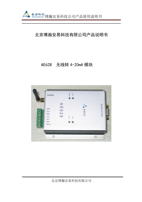
北京博瀚安易科技有限公司产品说明书AE628 无线转4-20mA模块北京博瀚安易科技有限公司一、概述无线转4-20mA模块,主要与本公司生产的无线温度变送器,无线压力变送器,无线流量计及无线密度仪,4-20mA转无线模块等无线发射端产品相配套的,将发射端的无线信号接收后,进行变送、转换、传输、运算,转换成需要的4-20mA信号。
与我司发射端的产品一起完成信号的传输工作。
二、功能特点●将我司的无线压力、温度、流量、液(物)位、密度等无线产品发射的无线数据接收,并转换成4-20mA输出;●无线输入●AO1、GND,AO2、GND为两路4-20mA输出;●通过RS232接口可以设定各种参数;RS232通道协议为MODBUS协议●RS232和4-20mA同步输出接收数据●体积小●性价比高●技术咨询QQ:583367295三、技术参数●供电电压:24VDC±10%●输入:无线信号●无线频率:433MHZ●无线增益:10dbm●无线距离:300米/500米(视距)●输出:两路4-20mA输出,RS232/RS485●负载能力:400欧●有线协议:MODBUS协议●型号:AE628●环境温度:-40℃~+85℃●环境湿度:5%~95%,无结露●振动:≤10g,f≤55Hz,振幅≤0.5mm●接地 :在电磁干扰大的地区,应将变送器和电缆屏蔽层良好接地四、安装及接线结构1、版面示意图2、接口说明2.1电源接口PGND :大地,可以不接。
VCC:24V+GND:24V-2.2 RS232/RS485接口RS232 接口/RS485接口2.3传感器接口AO1,GND :第1路接入。
AO1,为4-20mA的电流输入口。
GND为电流回路输出口。
AO2,GND :第2路接入。
AO2,为4-20mA的电流输入口。
GND为电流回路输出口。
2.3 运行指示2.3.1 Link1、Link2备用。
2.3.2 Power灯为电源指示灯,系统上电后,系统正常运行亮灯。
蓝牙天线设计资料

1. 简介
该文档是上海慧翰信息技术有限公司推出的蓝牙模块的硬件设计经验总结,适用于本公司的各个型号模块的硬件设计参考,敬请按型号区分要点。
如有何问题,请直接与本公司的工程师联系,您将会得到更详细的说明。
2. 天线设计
2.1 PIFA天线设计
该天线设计适用于FLC-BTMDC705及FLC-BTMDC732模块的设计。
2.1.1 尺寸要求
该天线是经过调频特性的理论计算得出的尺寸大小,并经过实际设计验证的经验值,跟板材及环境都有关系。
按如下规格设计最远距离(无遮挡)可达20米。
图 1
2.1.2 布线要求
首先,建议将天线按尺寸设计成元件封装,方便摆放及后续项目设计,并可以防止拖动造成尺寸大小变化,而来回修改。
其次,该天线是与地线连接的,天线有效部分的周围及其下层(即
背面)不应用有元器、布线,更不应该铺铜,否则影响信号发射和接收,甚至无法正常工作。
第
三,该天线的接地点要求大面积接地,并多打过孔。
第四,该天线要求设计在PCB板的板边,尽量朝前面板,并要求周围避开铁质结构件。
2.1.3 板材要求
板材请选用:FR4,介电常数为 4.2
2.2 外引天线设计
请断开PIFA天线的连接电路,并用10pF的电容连接外引天线。
外引天线的线材要求采用
50欧高频屏敝电缆,并在尾部去掉3CM长的屏敝层。
线头的中间信号线焊接在天线输出端,而
屏敝铁线也应该焊在就近地线位置,该天线尾部应放置于前面板靠前位置或者引至铁壳之外。
HG-RF04-F 双通道 MAX2771 射频模块产品说明书

HG-RF04-F双通道MAX2771射频模块产品说明书(支持任意卫星导航频点,参数可通过USB接口的虚拟串口配置)北京星源北斗导航技术有限责任公司2020 年 9 月11 日更多详细信息请致电星源北斗咨询!公司地址:北京市海淀区温泉镇显龙山路19号北辰香麓雅庭A座218室电话:136****9930传真:************QQ:5024141邮箱:***************1 产品概述表1 产品价格表图1 HG-RF04-F 射频模块GNSS 射频模块HG-RF04-F 主要用于接收任意两个GNSS 频点的卫星信号,支持中频数字信号输出,每个射频支持两个独立的射频输入(同时只能使用一个输入口),分别对应L1附近的频点和L2/L5/B3附近的频点,提供3.3V馈电,射频输入加入的阻抗匹配可接信号模拟器、多频天线。
HG-RF04-F的MAX2771芯片可以独立配置(基于MicroUSB虚拟串口,通信协议和HG-AF04兼容),可支持I路和Q路信号同时输出。
2 主要参数HG-RF04-F基本特性如下:1.射频芯片:MAX2771×2,可支持任意GNSS频点,比如L1/L2/L5, B1C/ B1I/B2a/B3I。
2.TCXO:16.369MHz。
3.射频接口:MMCX×2,提供3.3V天线馈电,其中HI口表示L1附近频点输入,LO口表示L2/L5/B3附近频点输入,每个射频HI口和LO口同时只能有一个接天线。
4.中频接口:⚫时钟输出:GPSCLK1,GPSCLK2可选的采样时钟:ADC_CLKIN1,ADC_CLKIN2⚫I支路数据:I1、I0⚫Q支路数据:Q1、Q05.供电方式:+5V供电6.体积:50mm×35mm。
3 接口关系图2 HG-RF04-F对外接口图4 尺寸图图3 HG-RF04-F尺寸图(默认单位为mm)5 装箱清单1.HG-RF04-F射频模块1块;2.配套文档:HG-RF04-F使用说明书;6 服务条款1、半个月内如产品硬件有质量问题可免费更换;2、提供3个月QQ技术支持;3、本产品允许客户把产品提供的配置参数用于最终产品中,但不允许将本产品提供的配置参数和原理图提供给任何第三方。
Modicon M238逻辑控制器的TM2ALM3LT模块数据表说明书

i s c l a i me r : T h i s d o c u m e n t a t i o n i s n o t i n t e n d e d a s a s u b s t i t u t ef o r a n d i s n o t t o b e u s e d f o r d e t e r m i n i ng s u i t a b i l i t y o r r e l i a b i l i t y o f th e s e p r o d u c t s f o r s p e ci f i c u s e r a p p l i c a t i o n sProduct datasheetCharacteristicsTM2ALM3LTanalog input/output module M238 - 2 inputs thermocouple/temp low level- 1 outputMainRange of productModicon M238 logic controller Product or component type Input/Output analog module Analogue input number 2Input levelLow levelAnalogue input typeTemperature probe - 100...500 °C 3-wire Pt probe differential Thermocouple 0...1200 °C thermocouple J differential Thermocouple 0...1300 °C thermocouple K differential Thermocouple 0...400 °C thermocouple T differential Analogue output number 1Analogue output type Current 4...20 mA Voltage 0...10 V Cross talk<= 2 LSBComplementaryRange compatibility Advantys OTB Twido Analogue input resolution 12 bits Analogue output resolution 12 bitsLSB value0.1 °C thermocouple0.15 °C temperature probe 2.5 mV voltage voltage 4.8 µA current current Input impedance >= 1 MOhm Load typeResistiveLoad impedance ohmic <= 300 Ohm current >= 2000 Ohm voltage Stabilisation time 20 msConversion time 20 ms + 1 controller cycle time Sampling duration<= 20 ms temperature probe <= 60 ms thermocoupleAcquisition period 60 ms per channel + 1 controller cycle time thermocouple 80 ms per channel + 1 controller cycle timeMeasurement error+/- 0.2 % of full scale - 100...500 °C 3-wire Pt probe 25 °C 0.2 % of full scale +/- 4 °C 0...1200 °C thermocouple J 25 °C 0.2 % of full scale +/- 4 °C 0...1300 °C thermocouple K 25 °C 0.2 % of full scale +/- 4 °C 0...400 °C thermocouple T 25 °C +/- 0.2 % of full scale 0...10 V 0...10 V 25 °C +/- 0.2 % of full scale 4...20 mA 4...20 mA 25 °C Temperature coefficient+/-0.006 %FS/°C - 100...500 °C 3-wire Pt probe +/-0.006 %FS/°C 0...1200 °C thermocouple J +/-0.006 %FS/°C 0...1300 °C thermocouple K +/-0.006 %FS/°C 0...400 °C thermocouple T +/-0.015 %FS/°C 0...10 V 0...10 V +/-0.015 %FS/°C 4...20 mA 4...20 mA Repeat accuracy +/-0.5 %FS input/output Non-linearity+/- 0.2 %FS temperature probe +/- 0.2 %FS thermocouple +/- 0.2 %FS current current +/- 0.2 %FS voltage voltage Output error +/- 1 %FS Output ripple <= 1 LSBTotal error+/-1 %FS temperature probe +/-1 %FS thermocouple +/-1 %FS current current +/-1 %FS voltage voltage Type of cableShielded cable Insulation between channel and internal logic Photocoupler SupplyExternal supply [Us] rated supply voltage 24 V DC Supply voltage limits 19.2...30 VElectrical connection 1 removable screw terminal block Current consumption 50 mA 24 V DC external 50 mA 5 V DC internal Product weight0.085 kgEnvironmentDielectric strength500 V between I/O channel500 V between the I/O and internal logic500 V between the I/O and the external supply circuit Width 23.5 mm Depth 70 mm Height90 mmOffer SustainabilitySustainable offer status Green Premium productRoHS (date code: YYWW)Compliant - since 1039 - Schneider Electric declaration of conformity Schneider Electric declaration of conformity REAChReference not containing SVHC above the threshold Reference not containing SVHC above the threshold Product environmental profileAvailableProduct environmental Product end of life instructionsAvailableProduct environmentalContractual warrantyWarranty period18 monthsDimensions DrawingsAnalog Mixed I/O Module (3-channel, Thermocouple/Temperature Probe/Voltage/Current)DimensionsNOTE: * 8.5 mm (0.33 in) when the clip-on lock is pulled out.DIN Rail MountingModule Mounting on a Panel Surface Mounting Hole LayoutWiring RequirementsCable Types and Wire Sizes for Removable Screw Terminal BlockAnalog Mixed I/O Module (3-channel, Thermocouple/Temperature Probe/Voltage/Current)Wiring Diagram Example2, 3 or 4 wires(1) 4 wires(2)Voltage/current preactuator (3)Thermocouple。
易科无线解决方案提供商 ETS1278R1825 V01 模块说明书
ETS1278R1825微功率模块说明书(18*25*2mm 射频前端)深圳易科软件有限公司Mb/VX:QQ:8246 8188https:// https://Email:Factory: 深圳市龙岗区坂田风门路52号金源科技园2栋305室版权声明:本产品为我司ODM产品,任何个人和公司都可以使用和宣传。
如有更好建议对本手册进行修改,请同时通知我们。
对应用产品有开发,设计需求和合作,请及时联络。
信任,合作,共赢!目录一、 模块介绍二、 产品特点三、 应用范围四、 尺寸与引脚定义五、 技术参数六、 模块应用注意事项七、 常见故障及排除方法八、 客户订制要求一、 模块介绍模块采用SX127x系列收发射频芯片,采用LORA扩频无线射频技术,数字处理技术,高抗干扰,高稳定性和高性价比。
用户只需通过模组提供的SPI数字接口,控制芯片内部寄存器,实现对SX127x 参数配置、无线数据收发等功能。
该模块具有尺寸小,灵敏度高,传输距离远,通讯速率高,延时小。
用户可以根据自己的要求来定制模块尺寸,输出功率,频率段等参数,或者直接将将模块布板到用户的PCB上,提升客户的产品水平和节省成本。
二、 产品特点微功率发射,最大输出20dbm,可通过设置控制发射功率。
工作频段:137MHZ-1020Mhz 等免申请频段,可根据用户的要求定制工作频段。
接收灵敏度最高达-148dBm@1200bps,在天线高度2米时,开阔地无干扰情况下可达3000米。
三、 应用范围无线排队设备,酒店电子门锁、生物识别门禁管理系统智能家居、家庭电器和灯光智能控制医疗和电子仪器仪表自动化控制智能教学设备、婴儿监护、医病房呼叫系统防盗报警,车辆防盗,智能卡,铁路机车远程检测水、电、煤气,暖气自动抄表收费系统或无功补偿及电网监测无线会议表决、打分系统,PDA终端、无线点菜系统LED屏无线传输文字,图片和无线控制,电子衡器、无线吊秤、车辆监测、老化设备检测,工业设备数据无线传输以及工业环境监测视频监控云台控制,门禁考勤读卡器气象/油井/水利设备信息采集以及自然环境检测资产管理和人员区域定位、物流供应链管理。
- 1、下载文档前请自行甄别文档内容的完整性,平台不提供额外的编辑、内容补充、找答案等附加服务。
- 2、"仅部分预览"的文档,不可在线预览部分如存在完整性等问题,可反馈申请退款(可完整预览的文档不适用该条件!)。
- 3、如文档侵犯您的权益,请联系客服反馈,我们会尽快为您处理(人工客服工作时间:9:00-18:30)。
FLC-BTMDC732-I2UE /E2SpecificationType:PreliminaryDocument Number: FLC-BTMDC732-I2UE/E2-001Version: 0.1Release Date: June 10, 2009Flaircomm Technologies Inc.Address: 4F Keyuan Building, No.5 Bibo Road, Zhangjiang Hi-Tech Zone, Shanghai, PRC, 201203Telephone:86-21-51088733Fax:86-21-62494858Release RecordVersion Number Release Date Comments0.1 June 10, 2009 PreliminaryTABLE OF CONTENTS1.ORDERING INFORMATION (5)2.INTRODUCTION (6)2.1B LOCK D IAGRAM (6)2.2F EATURES (7)3.GENERAL SPECIFICATION (8)4.DIMENSION AND PIN DEFINITION (10)4.1D IMENSION (10)4.2P IN D EFINITION (10)4.3E LECTRICAL C HARACTERISTICS (11)5.INTERFACE SPECIFICATION (12)5.1UART I NTERFACE (12)TABLE OF FIGURESFigure 1: FLC-BTMDC732-I2U Block Diagram (6)Figure 2: FLC-BTMDC7xx-I2UE Dimension and Pin definitions(Unit: mm) (10)Figure 3: Connect to Host CPU (12)TABLE OF TABLESTable 1: Ordering Information (5)Table 2: General Specification (8)Table 3: Pin Definition (10)Table 4: Absolute Maximum Rating (11)Table 5: Recommended Operating Conditions (11)1. Ordering InformationPart Name Has EEPROM ?FLC-BTMDC732-I2UE No FLC-BTMDC732-I2UE2 YesTable 1: Ordering Information2. IntroductionFLC-BTMDC732-I2UE (E2) is a fully integrated Bluetooth module. It is one of the BlueTone TM series products developed by Flaircomm. FLC-BTMDC732-I2U is based on Flaircomm’s BQB certified FLC-BTMDC732 module with specific interface design to meet automobile industrial customers’ needs.FLC-BTMDC732-I2UE(E2) complies with Bluetooth specification version 2.0. It integrates RF, Baseband controller, antenna, etc., a completed Bluetooth subsystem, in an ultra small package. FLC- BTMDC732-I2U supports HS/HF, A2DP, AVRCP, and OPP profiles. It provides an UART interface, three user programmable I/Os, stereo speaker outputs, microphone inputs and a USB port.FLC-BTMDC732-I2UE2 has a 64Kbits serial EEPROM,it can store the phonebook。
FLC-BTMDC732-I2UE(E2) can be programming through UART port. Please refer to FLC-BTMDC7xx modules programming guide for details.2.1 Block DiagramFigure 1: FLC-BTMDC732-I2UE/E2 Block Diagram2.2 Featuresz BlueTooth Statusz HS/HF, A2DP, AVRCP, and OPP Profilesz Make and Receive Callz Accept/Reject/End Callsz Call Waitingz Conference Callz Last Number Redialz Voice Dialz Store the phonebook (MDC732-I2UE2)z Caller IDz Call Progress Informationz Stereo audio play, stop, pause, forward, backward.3. General SpecificationTable 2: General SpecificationProduct BlueTone TM Series Bluetooth Module Model FLC-BTMDC732-I2UE/E2 Bluetooth SpecificationStandard Bluetooth 2.0, Class II Frequency Band 2.4~2.48GHz Modulation Method GFSK, 1Mbps, 0.5BT GaussianMaximum Data Rate Asynchronous: 723.2kbps/57.6kbps Synchronous: 433.9kbps/433.9kbpsHopping 1600hops/sec,1MHz channel spaceRF Input Impedance 50 ohmsBaseband Crystal OSC 16MHzInterface UART, PIO, Speaker, MicrophoneProfiles HS/HF, A2DP, AVRCP, and OPP Profiles etc.Operation Range 10 meters (33 feet)Sensitivity -80dBm@0.1%BER RF TX Power 0dBmConnectivity Point to Multi-PointAudio SpecificationAudio Codec 16bitsDAC SNR Typical 70dBAudio Encryption 128bitsDimensionDimension 35mmX25mmX3.7mmPowerSupply Voltage 3.3 ~ 5.5V DCWorking Current 152mA Typical Talking at DH5Working Current 221mA Typical @A2DPStandby Current 1 4.1mA Typical (None link)Standby Current 2 4.5mA Typical (HFP link)Operation EnvironmentTemperature -40ºC to +85ºCHumility 10%~90%Non-Condensing Certifications BQB4. Dimension and Pin Definition4.1 DimensionFigure 2: FLC-BTMDC7XX-I2UE/E2 Dimension and Pin definitions(Unit: mm)4.2 Pin DefinitionTable 3: Pin DefinitionPin Symbol I/O Description1 PIO10 I/O Programmable input/output line .Bi-directional with programmable strength internal pull-up/down2 L_Audio O Left channel Audio out3 R_Audio O Right channel Audio out4 AGND+ - Audio Ground5 MIC+ I Microphone input. Internal power Supply.6 MICGND - Microphone Ground7 VCC I Power Supply.3.3V ~ 5.5V.8 GND - Ground9 TXD O UART data output. CMOS output, tri-state, with weak internal pull-up.10 RXD I UART data input. CMOS input with weakinternal pull-down.11 INT# I/O Interruption IN/Out12 LED0(PIO0) I/O LED04.3 Electrical CharacteristicsTable 4: Absolute Maximum RatingRating Minimum Maximum Storage Temperature -40°C +150°C RXD,INT# Voltage -0.4V +3.7V VCC Voltage -0.4V +5.6V L _Audio/ R _Audio DCVoltage-3V +5VTable 5: Recommended Operating ConditionsOperating Condition Minimum Typical MaximumOperating Temperature Range -40°C -- +85°C5. InterfaceSpecification5.1 UART InterfaceFigure 3: Connect to Host CPU。