MS50SFA1C透传从模块规格书V4.1
伊顿 MTL5500 FSM 安全手册 模拟输入模块 A 型号 说明书

FUNCTIONAL SAFETY MANAGEMENTThese products are for use as elements within a Safety System conforming to the requirements of IEC61508:2010 and enable a Safety Integrity Level of up to SIL 2 to be achieved for the instrument loop in asimplex architecture.Eaton Electric Ltd, Luton is a certified Functional Safety Management company meeting the requirementsof IEC61508:2010 Part 1, Clause 6.* Subject to special conditions for detection of out-of-range signal currents. Refer to content of this manual for details.2SM4541A/AS, 5541A/AS, 4544A/AS, 5544A/AS rev 2 This manual supports the application of the products in functional-safety related loops. It must be usedin conjunction with other supporting documents to achieve correct installation, commissioning andoperation. Specifically, the data sheet, instruction manual and applicable certificates for the particularproduct should be consulted, all of which are available on the MTL web site.In the interest of further technical developments, Eaton reserve the right to make design changes.Contents1 Introduction31.1 Applicationandfunction 31.2 Variantdescription 31.3 Product build revisions coveredbythismanual 42 System configuration52.1 Associated system components 63 Selection of product and implications 64 Assessment of functional safety64.1 HardwareSafetyI ntegrity 64.2 Systematic Safety Integrity 74.3 SIL Capability 74.4 Example of use in a safety function 74.5 EMC 84.6 Environmental 85 Installation86 M aintenance97 Appendices97.1 Appendix A: Summary of applicablestandards 97.2 Appendix B: Proof T est Procedure,MTLx541A/AS, MTLx544A/AS Modules 10 - 12 Analogue Input Modules with passive inputfor 4-wire transmitters† These modules have an inherent fault tolerance of 0.3SM4541A/AS, 5541A/AS, 4544A/AS, 5544A/AS rev 21 INTRODUCTION1.1 Application and functionThe Analogue Input module types MTLx541A/MTLx541AS (single channel) and MTLx544A/MTLx544AS (dual channel) are intrinsic safety isolators that interface with process measurement transmitters located in a hazardous area of a process plant. They are also designed and assessed according to IEC 61508 for use in safety instrumented systems up to SIL 2.The MTLx541A provides an input for a separately-powered 4/20mA transmitter located in a hazardousarea, and repeats the transmitter current into a load in the safe area. The MTLx544A supports two identical channels for use with two separate transmitters. The MTLx541AS and MTLx544AS versions act as a current sink for the safe area connection rather than driving the current into the load.All the modules allow bi–directional transmission of HART communication signals superimposed on the4/20mA loop current, so that the transmitter can be interrogated either from the operator station or by a hand-held communicator (HHC).There are no configuration switches or operator controls to be set on the modules. These modules are members of the MTL4500 and MTL5500 range of products.1.2 Variant DescriptionFunctionally the MTL4500 and MTL5500 range of modules are the same but differ in the following way:- the MTL4500 modules are designed for backplane mounted applications- the MTL5500 modules are designed for DIN-rail mounting.In both models the hazardous area field-wiring connections (terminals 1,2, and optionally 4,5) are made through the removable blue connectors, but the safe area and power connections for the MTL454xA/MTL454xAS modules are made through the connector on the base, while the MTL554xA/MTL554xAS modules use the removable grey connectors on the top and side of the module.Note that the safe-area connection terminal numbers differ between the backplane and the DIN-rail mounting models.The analogue input models covered by this manual are:Note: To avoid repetition, further use of MTLx54xA and MTLx54xAS in this document can be understood to include both DIN-rail and backplane models. Individual model numbers will be used only where there is a need to distinguish between them.All the module types described in this manual have the same connectivity for the field signals, supporting 4-wire process transmitters or currents sourced in the hazardous area. The connection of the repeated current signals into the input measurement channels for the safety logic system follows the arrangement shown in the following diagram. When the input channels of the Safety Instrumented System (SIS) are providing power for the loop, the ‘S’ variants of the isolator modules are used to ‘sink’ the measuring current.In the other cases the isolator modules ‘source’ the measuring current that flows into a load resistor inside theinput card of the Safety Instrumented System.4SM4541A/AS, 5541A/AS, 4544A/AS, 5544A/AS rev 22+1-Pwr (Safe area current source)B A 2+1-Pwr A BMTL5541A, MTL5541AS 1112current source (Safe area current sink) Figure 1.1 – Input and output connections 1.3 Product build revisions covered by this manual The information provided in this manual is valid for the product build revisions listed in the following table: The product build revision is identified by the field ‘CC’ in the module Product Identification Number that appears at the bottom left-hand corner of the side label: The CC field immediately precedes the 7-digit Serial Number field, DDDDDDD. Example:5SM4541A/AS, 5541A/AS, 4544A/AS, 5544A/AS rev 22 System configurationAn MTLx54x module may be used in single-channel (1oo1) safety functions up to SIL 2. The worked example in this manual is for a SIL 2 application.The figure below shows the system configuration and specifies detailed interfaces to the safety-related and non safety-related system components. It does not aim to show all details of the internal module structure, but is intended to support understanding for the application.Figure 2 – System ConfigurationThe MTLx54xA/MTLx54xAS modules are designed to receive an active 4-20mA signal from separatelypowered process transmitters in the hazardous area and to repeat the current flowing in the field loop to the safe-area load. The shaded area indicates the safety-related system connection, while the power supply con-nections are not safety-related. The term ‘Logic Solver’ has been used to denote the safety system performing the monitoring function of the process loop variable.Note: When using the MTLx544A/MTLx544AS dual-channel modules, it is not appropriate for both channels to be used in the same loop, or the same safety function, as this creates concerns regarding common-cause failures. Consideration must also be given to the effect of common-cause failures when both loops of a dual-channel module are used for different safety functions.2.1 Associated System ComponentsThere are many parallels between the loop components that must be assessed for intrinsic safety as well asfunctional safety. In both situations the contribution of each part is considered in relation to the whole.The MTLx54xA/MTLx54xAS modules are components in the signal path between safety-related process trans-mitters and safety-related control systems. The transmitter or other field device must be suitable for the processand have been assessed and independently verified for use in functional safety applications.The field instrument and Analogue input card of the Logic Solver shall have a normal operating range of 4-20mAbut be capable of working over an extended range of 3 to 22mA for under- and over-range. The Logic Solver shallhave the ability to detect and annunciate input currents higher than the threshold of 21mA and lower than thethreshold of 3.6mA to determine out-of-range conditions.Note that the transmission of HART data is not considered as part of the safety function and is excluded fromthis analysis. However, for HART data communication to take place, the input impedance of the receiving equip-ment must be at least 240R.3 Selection of product and implicationsThe safe area output signal from the MTLx541A/AS and MTLx544A/AS modules is within the operating range of4-20mA under normal conditions. If the field wiring to the transmitter or connection between the isolator and logicsolver is open-circuit then the loop current will fall to less than 3.6mA and close to zero. If the field wiring connectionbetween the transmitter and isolator is short-circuited, the loop current will also fall to below 3.6mA.For module types MTLx541A and MTLx544A that source the 4-20mA signal in the safe area circuit, then the currentseen by the logic solver will fall to less than 3.6mA and close to zero if the connection between the isolator and logicsolver is shorted.For module types MTLx541AS and MTLx544AS that sink the 4-20mA signal in the safe area circuit, then the currentseen by the logic solver will rise to a value greater than 21mA if the connection between the isolator and logic solveris shorted.In both cases, the fault condition must be detected by the logic solver in Functional Safety applications. This shouldalso include the detection of power supply failures which cause the output of the isolator to fall to zero mA.4 Assessment of Functional Safety4.1 Hardware Safety IntegrityThe hardware assessment shows that MTLx541A/MTLx541AS and MTLx544A/MTLx544AS modules:• have a hardware fault tolerance (HFT) of 0• are classified as Type A devices (“non-complex” component with well-defined failure modes)• have no internal diagnostic elementsThe failure rates of these modules at an ambient temperature of 45°C are as follows:*(FITs means failures per 109 hours or failures per thousand million hours)• Reliability data for this analysis is taken from IEC TR 62380:2004 Reliability Data Handbook.• Failure mode distributions are taken principally from IEC 62061:2005 Safety of Machinery.• Stated failure rates for dual-channel modules apply to a single channel.It is assumed that the module is powered from a nominal 24V dc supply and operating at a maximum ambienttemperature of 45°C.6SM4541A/AS, 5541A/AS, 4544A/AS, 5544A/AS rev 24.2 Systematic Safety IntegrityThe MTLx54x modules have a systematic safety integrity measure of SC 2. This has been established using,as described in IEC 61508-2: 2010, section 7.4.2.2 c.compliance Route 1S4.3 SIL CapabilityConsidering both the hardware safety integrity and the systematic capability, this allows the modules to beused in safety functions up to SIL 2 in a simplex architecture (HFT=0), provided SFF ≥60% is the case for the,application. The hardware safety integrity assessment has been conducted according to compliance Route 1Has described in IEC 61508-2:2010, section 7.4.4. (See example below).Note:• Independent of hardware architecture and systematic capability considerations, the hardware probability offailure for the entire safety function needs to be calculated for the application to ensure the required PFH (for ahigh or continuous demand safety function) or PFD AVG (for a low demand safety function) for the SIL is met.4.4 Example of use in a safety functionIn this example, the application context is assumed to be:• the safety function is to repeat current within ±2%• the logic solver will diagnose currents above 21mA and below 3.6mA as faults and take appropriateactionThe failure modes shown above can then be defined as:The failure rates of the MTL4541A and MTL5541A for these categories are then (FITs):In this example, the safe failure fraction (SFF) is 84.4%.*ne is not used in the calculation of SFF. Defining the “output current correct within ±2%” failure mode asrepresents a conservative approach to the calculation of SFF. Interpreting this failure mode as su(safe,neundetected) may also be considered and yields an SFF value of 87.7%.Accordingly, the SFF of all module types described in this manual, when used in the same application,are as follows:SM4541A/AS, 5541A/AS, 4544A/AS, 5544A/AS rev 274.5 E M CThe MTL4500 and MTL5500 modules are designed for operation in normal industrial electromagnetic environ-ment but, to support good practice, modules should be mounted without being subjected to undue conductedor radiated interference, see Appendix A for applicable standards and levels.4.6 EnvironmentalThe MTL4500 and MTL5500 modules operate over the temperature range from -20°C to +60°C, and at up to95% non-condensing relative humidity.The modules are intended to be mounted in a normal industrial environment without excessive vibration, asspecified for the MTL4500 & MTL5500 product ranges. See Appendix A for applicable standards and levels.Continued reliable operation will be assured if the exposure to temperature and vibration are within the valuesgiven in the specification.5 InstallationThere are two particular aspects of safety that must be considered when installing the MTL4500 or MTL5500modules and these are:• Functional safety• Intrinsic safetyReference must be made to the relevant sections within the instruction manual for MTL4500 range (INM4500)or MTL5500 range (INM5500) which contain basic guides for the installation of the interface equipment tomeet the requirements of intrinsic safety. In many countries there are specific codes of practice, together withindustry guidelines, which must also be adhered to.Provided that these installation requirements are followed then there are no additional factors to meet theneeds of applying the products for functional safety use.To guard against the effects of dust and water the modules should be mounted in an enclosure providing atleast IP54 protection degree, or the location of mounting should provide equivalent protection such as inside anequipment cabinet.In applications using MTL4500 range, where the environment has a high humidity, the mounting backplanesshould be specified to include conformal coating.8SM4541A/AS, 5541A/AS, 4544A/AS, 5544A/AS rev 26 M aintenanceTo follow the guidelines pertaining to operation and maintenance of intrinsically safe equipment in a hazardousarea, yearly periodic audits of the installation are required by the various codes of practice. In addition, proof-testing of the loop operation to conform with functional safety requirements should be carried out at theintervals determined by safety case assessment.Proof testing must be carried out according to the application requirements, but it is recommended that this becarried out at least once every three years.Refer to Appendix B for the proof testing procedure of the MTLx541A/AS and MTLx544A/AS modules.Note that there may also be specific requirements laid down in the E/E/PE operational maintenance procedurefor the complete installation.If an MTLx541A/AS and MTLx544A/AS module is found to be faulty during commissioning or during the normallifetime of the product, then such failures should be reported to the local MTL office. When appropriate, a Cus-tomer Incident Report (CIR) will be notified by Eaton to enable the return of the unit to the factory for analysis.If the unit is within the warranty period then a replacement unit will be sent.Consideration should be given to the service lifetime for a device of this type, which is in the region of tenyears. Operating an MTLx541A/AS and MTLx544A/AS module for longer than this period could invalidate thefunctional safety analysis, meaning that the overall safety function no longer meets its target SIL. If high failurerates of the MTL modules are detected, indicating that they have entered the ‘end of life phase’ of their servicelife, then they should be replaced promptly.7 Appendices7.1 Appendix A: Summary of applicable standardsThis annex lists all standards referred to in the previous sections of this document:SM4541A/AS, 5541A/AS, 4544A/AS, 5544A/AS rev 2910SM4541A/AS, 5541A/AS, 4544A/AS, 5544A/AS rev 27.2 Appendix B: Proof T est Procedure, MTLx541A/AS, MTLx544A/AS ModulesConfirmation, through testing, that a safety function will operate as designed, is a necessary periodic activity to ensure that the probability of failure upon demand (PFDavg) is maintained.In some applications, the user may prefer to conduct a proof test on the overall safety instrumented function without dismantling or disconnecting the individual instrumentation components, in order to avoid disturbing the integrity of the installation.However, where it is deemed desirable to perform proof testing on the MTL modules individually, thefollowing procedure may be used. Proof tests of the other components of the loop must then be conducted in accordance with their manufacturers’ instructions, to maintain the integrity of the overall safety function. Alternative proof tests may be devised and applied, provided they give a similar level of test coverage that is appropriate to the safety function.The tests described here - see Figure 7.1 - compare the output current of the MTL isolator with the input current (A1) over the required range of operation, and measure the “error current” i.e. the difference between the two - as indicated on A2. The tests should be employed per channel, as appropriate.Figure 7.1 - Basic test arrangementAmmeter A2 must be capable of measuring currents of either polarity. If it is not an auto-ranging instrument, set it to a high range before switch on, and then adjust sensitivity to obtain the required reading.Proof T est ProcedureTest sequence:1. System - Normal operation test2. Input /Output characteristic functional safety test3. System - Normal operation test10k W10k W Modules types MTL4541A, MTL4544A,MTL5541A, MTL5544A Modules types MTL4541AS, MTL4544AS, MTL5541AS, MTL5544AS1 System - Normal operation testMake sure that the module to be tested is operating normally in the target system, without errors and in anenergised mode. If the module is in a faulty or de-energised loop, restore normal fault-free and energisedoperation before testing.2 Input/Output characteristic functional safety testObserve normal anti-static precautions when handling equipment during device testing. Remove the unit fromthe target system and connect it as shown in Figure 7.2. This figure shows the arrangement for the MTLx541A/AS single-channel modules; for equivalent connections for the MTLx544A/AS dual-channel modules, refer tothe relevant product data sheets. Note that it is acceptable to leave the unit in the target system but only afterensuring that the all the hazardous area input and safe area output terminals have been disconnected from thesystem and are available for test. Alternatively, for the backplane-mounted MTL4500 range modules, a separatebackplane can be used to provide access to the power and output connections.Note that the combination of the 24V power supply and variable resistor RV1 in the hazardous area connectioncan be provided by a suitable industrial current simulator, which is likely to be more readily available. Also,the 250R resistor does not need to be a precision type; any value in the range 200-300R is acceptable wouldsuffice, such as a standard value of 240R.Where a second power supply is introduced for testing the MTLx541AS or MTLx544AS module variants, notethat both power supplies must be floating and not share a common 0V connection.During testing, a 24V nominal system power supply in the range 20.0 to 35.0V should be connected betweenterminals 13 and 14 (+ve to terminal 14).Figure 7.2 - Connections for testing the MTL5541A/AS and MTL4541A/AS modulesSM4541A/AS, 5541A/AS, 4544A/AS, 5544A/AS rev 21112SM4541A/AS, 5541A/AS, 4544A/AS, 5544A/AS rev 2Channel 1Channel 2MeasurementsMake the following measurements. It is recommended to record the results in a table such as that shown on the next page. 1. Adjust resistor RV1 to vary the loop current (measured by Ammeter A1) through the range 4 to 20mA. (Tests 1 - 5 in table)2. The measured current imbalance (measured by Ammeter A2) over this range should not exceed ±50μA.3. Adjust RV1 to vary the current (A1) to 3.5mA and then 21.5mA (tests 6 & 7 in table).4. The measured current imbalance (A2) at these currents should not exceed ±200μA.5. Record the supply voltage Vs.If appropriate, repeat these measurements for Channel 2.3 System - Normal operation testDisconnect the test setup from the unit and reconnect the original system configuration. Make sure that the tested unit operates normally in the target system, as before, without errors and in energised mode.Date: ______/______/__________ Supply voltage Vs: ______________V dc Module type: _________________Serial No: ______________________________THIS PAGE IS LEFT INTENTIONALL Y BLANKSM4541A/AS, 5541A/AS, 4544A/AS, 5544A/AS rev 213THIS PAGE IS LEFT INTENTIONALL Y BLANK14SM4541A/AS, 5541A/AS, 4544A/AS, 5544A/AS rev 2THIS PAGE IS LEFT INTENTIONALL Y BLANKSM4541A/AS, 5541A/AS, 4544A/AS, 5544A/AS rev 215EUROPE (EMEA):+44 (0)1582 723633********************THE AMERICAS:+1 800 835 7075*********************ASIA-PACIFIC:+65 6 645 9888***********************The given data is only intended as a product description and should not be regarded as a legal warranty of properties or guarantee. In the interest of further technical developments, we reserve the right to make design changes.Eaton Electric Limited,Great Marlings, Butterfield, LutonBeds, LU2 8DL, UK.Tel: + 44 (0)1582 723633 Fax: + 44 (0)1582 422283 E-mail:********************© 2024 EatonAll Rights ReservedPublication No. SM4541A/AS, 5541A/AS, 4544A/AS,5544A/AS rev 2 160424 April 2024Connect with Eaton, MTL:AUSTRALIAEaton Electrical (Australia) Pty Ltd,10 Kent Road, Mascot, New South Wales, 2020, Australia Tel: +61 1300 308 374 Fax: +61 1300 308 463E-mail:*********************BeNeLuxMTL Instruments BVAmbacht 6, 5301 KW ZaltbommelThe NetherlandsTel: +31 (0)418 570290 Fax: +31 (0)418 541044E-mail:*********************CHINACooper Electric (Shanghai) Co. Ltd955 Shengli Road, Heqing Industrial ParkPudong New Area, Shanghai 201201Tel: +86 21 2899 3817 Fax: +86 21 2899 3992E-mail:****************FRANCEMTL Instruments sarl,7 rue des Rosiéristes, 69410 Champagne au Mont d’Or FranceTel: +33 (0)4 37 46 16 53 Fax: +33 (0)4 37 46 17 20E-mail:*******************GERMANYMTL Instruments GmbH,Heinrich-Hertz-Str. 12, 50170 Kerpen, GermanyTel: +49 (0)22 73 98 12 - 0 Fax: +49 (0)22 73 98 12 - 2 00E-mail:*******************INDIAMTL India,No.36, Nehru Street, Off Old Mahabalipuram Road Sholinganallur, Chennai - 600 119, IndiaTel: +91 (0) 44 24501660 /24501857 Fax: +91 (0) 44 24501463 E-mail:***********************ITAL YMTL Italia srl,Via San Bovio, 3, 20090 Segrate, Milano, ItalyTel: +39 02 959501 Fax: +39 02 95950759E-mail:******************JAPANCooper Crouse-Hinds Japan KK,MT Building 3F, 2-7-5 Shiba Daimon, Minato-ku,Tokyo, Japan 105-0012Tel: +81 (0)3 6430 3128 Fax: +81 (0)3 6430 3129E-mail:****************NORWA YNorex ASFekjan 7c, Postboks 147,N-1378 Nesbru, NorwayTel: +47 66 77 43 80 Fax: +47 66 84 55 33E-mail:*************RUSSIACooper Industries Russia LLCElektrozavodskaya Str 33Building 4Moscow 107076, RussiaTel: +7 (495) 981 3770 Fax: +7 (495) 981 3771E-mail:*******************SINGAPOREEaton Electric (Singapore) Pte Ltd100G Pasir Panjang RoadInterlocal Centre#07-08 Singapore 118523#02-09 to #02-12 (Warehouse and Workshop)Tel: +65 6 645 9888 ext 9864/9865Fax: +65 6 645 9811E-mail:***********************SOUTH KOREACooper Crouse-Hinds Korea7F. Parkland Building 237-11 Nonhyun-dong Gangnam-gu, Seoul 135-546, South Korea.Tel: +82 6380 4805 Fax: +82 6380 4839E-mail:*******************UNITED ARAB EMIRATESCooper Industries/Eaton CorporationOffice 205/206, 2nd Floor SJ Towers, off. Old Airport Road, Abu Dhabi, United Arab EmiratesTel: +971 2 44 66 840 Fax: +971 2 44 66 841E-mail:*****************UNITED KINGDOMEaton Electric Ltd,Great Marlings, Butterfield, LutonBeds LU2 8DLTel: +44 (0)1582 723633 Fax: +44 (0)1582 422283E-mail:********************AMERICASCooper Crouse-Hinds MTL Inc.3413 N. Sam Houston Parkway W.Suite 200, Houston TX 77086, USATel: +1 281-571-8065 Fax: +1 281-571-8069E-mail:*********************。
VC-01-Kit 规格书说明书
VC-01-Kit规格书V1.0.0VC- -Kit规格书版本V . .版权 ©文件履历表目录1.产品概述 (4)1.1.特性 (5)2.主要参数 (6)2.1.静电要求 (6)2.2.电气特性 (7)2.3.功耗 (7)3.外观尺寸 (8)4.指示灯及按键说明 (9).管脚定义 (10).原理图 (12).产品相关型号 (13)8.固件烧录方式说明 (13)9.产品包装信息 (14)10.联系我们 (14)免责申明和版权公告 (15)注意 (15)1.产品概述VC-01-Kit是针对VC-01模组设计的开发板,该底板与VC-02-Kit共用。
开发板上集成了CH340C串口转USB芯片,提供基础的调试接口及USB升级接口;唤醒灯及冷暖灯的设计,提供了状态指示及控制指示,且方便调试简单的控制功能。
VC-01是深圳市安信可科技有限公司开发的一款低成本纯离线语音识别模组。
该模组使用云知声推出的语音芯片US516P6,在语音识别技术上不断优化和创新算法,离线识别算法与芯片架构深度融合,为客户提供超低成本的离线语音识别方案,可广泛且快速应用于智能家居,各类智能小家电,86盒,玩具,灯具等需要语音操控的产品。
US516P6芯片采用32bit RSIC架构内核,并加入了专门针对信号处理和语音识别所需要的DSP指令集,支持浮点运算的FPU运算单元,以及FFT加速器。
VC-01支持150条本地指令离线识别,支持RTOS轻量级系统,具有丰富的外围接口,以及简单友好的客制化工具。
图1US516P6芯片架构图1.1.特性内核32bit RISC内核,运行频率240MHz支持DSP指令集以及FPU浮点运算单元FFT加速器:最大支持1024点复数FFT/IFFT运算,或者是2048点的实数FFT/IFFT 运算云知声定制化语音算法算子存储内置242KB高速SRAM内置2MB FLASH音频输入输出灵活配置支持 . / . / . V IO支持1路模拟Mic输入,SNR≥94db支持双声道DAC输出支持中英文语音指令供电和时钟支持5V电源输入内置5V转3.3V,3.3V转1.2V LDO为芯片供电RC 12MHz时钟源和PLL锁相环时钟源内置POR(Power on Reset),低电压检测和看门狗外设所有GPIO均可配置为外部中断输入和唤醒源1个全双工UART最高速率3Mbps。
北京捷麦通信器材有限公司 R4050 开关量模块用户手册说明书
2013年10月北京捷麦通信器材有限公司R4050开关量模块用户手册 DATA ACQUISITION MODULES *************目录1概述 (3)1.1 特点 (3)1.2 外观和安装 (3)1.3 技术指标 (4)1.4指示灯状态 (4)2 电路连接 (5)2.1 输入电路连接 (5)2.2 输出电路连接 (6)2.3 通信电路的连接 (7)2.4 模块的输出值 (7)3 通用指令和模块的基本设置 (7)3.1 指令的基本格式 (7)3.2 设置模块配置-%AANNTTCCFF (9)3.3读配置信息-$AA2 (10)3.4读版本信息-$AAF (10)3.5 读复位状态-$AA5 (11)3.6 读模块名-$AAM (11)3.7写模块名-~AAO(数据) (12)4 采集和输出指令 (13)4.1同步采样-#** (13)4.2读同步数据-$AA4 (14)4.3数字输出-#AABBDD (14)4.4设置数字输出-@AA(数据) (15)4.5读数字输出/输入状态-$AA6 (16)4.6读数字输入/输出状态-@AA (16)4.7 读锁存状态-$AALS (17)4.8 清除锁存状态-$AAC (18)4.9 读入计数值-#AAN (19)4.10 清计数器-$AACN (19)5 遥控和报警指令及应用 (20)5.1 模式 (20)5.2读模块模式-#AAM (22)5.3设置模块模式-#AAMAB (23)5.4 读遥控目的地址-#AAR (24)5.5写遥控目的地址-#AAR(数据) (24)5.6读重发间隔时间-#AAT (25)5.7设置重发间隔时间-#AATDD (25)6 看门狗的使用和指令 (26)6.1 ~** (26)6.2 ~AA0 (27)6.3 ~AA1 (27)6.4~AA2 (28)6.5 ~AA3EVV (28)6.6 ~AA4V (29)6.7 ~AA5V (30)————————————————————————————————————————————————附件1:ASCII码对照表 (31)————————————————————————————————————————————————1概述1.1 特点R4050模块是R4000系列采集模块中的开关量输入输出模块,具有7路电压开关量输入,8路晶体管集电极开路输出。
深圳云里物里科技股份有限公司蓝牙模块MS50SFA1说明书

股票代码:872374产品型号MODEL NO/DESCRIPTION产品名称蓝牙从模块产品型号MS50SFA1适用固件版本V2.4.x Version V1.0发布时间2020-05-26目录1. 产品概述 (3)2. 应用领域 (4)3. 模块尺寸图 (4)4. 电气参数 (5)5. 模块管脚图 (6)6. 引脚定义 (6)7. 模块使用操作说明 (8)8. 功耗参数 (17)9. PCB设计说明 (18)10. MCU参考代码 (19)11. 模块原理图 (22)12. 回流焊温度曲线图 (23)13. 支持设备 (23)14. 注意事项 (23)15. 包装信息 (24)16. 认证信息 (25)17. 质量保证 (25)附件:版本说明 (26)1.产品概述MS50SFA1串口从模块采用nRF52810 芯片,通过UART(串口)操作可以实现模块与手机(或其它主设备)之间数据传输。
本模块为从模块,有广播和连接状态,可通过命令设置和查看模块的广播名称,修改广播间隔和连接间隔等参数。
使用该模块用户可以快速把数据以蓝牙方式进行传输。
产品特点产品效果图MS50SFA(V1.x)PCB天线产品反面★ 远距离:10-60米(空旷环境);★ BLE协议栈深度优化,睡眠功耗1uA以下;★ 传输速率最快可达11kB/s;★ 支持供电电压检测;★ 支持串口指令配置;★ 支持 Android 4.3+,iOS7.0+;★ 无需 MFi;★ 通过BQB认证(证书编号QDID:138541);★ 带屏蔽罩。
(默认单位:mm 默认公差:±0.1)3.模块尺寸图2.应用领域该模块主要用于短距离的数据无线传输领域。
可以方便的和PC机的蓝牙设备相连,也可以与智能手机之间的数据互通。
避免繁琐的线缆连接,能直接替代串口线。
可广泛应用于智能家居、智能穿戴设备、消费电子、智慧医疗、安防设备、汽车设备、运动健身设备、仪器仪表、远程遥控等需要低功耗蓝牙系统的领域。
FLW-801C 产品使用说明书
文档类别:维护文档密级:保密FLW-801C版权与许可深圳市畅锐科技有限公司版权所有,翻印必究。
除非版权法允许,否则,在事先未经书面许可的情况下,严禁复制、改编或翻译本手册。
与此手册相关用户具有以下权力:A:打印本手册以获得其硬盘拷贝,用于个人、内部或公司用途,而不得用于销售、转售或分发目的;B:将本手册仅作为深圳市畅锐科技有限公司自助产品的维护使用。
文档声明本文所含信息如有更改,恕不另行通知。
本公司不对本书作任何担保。
本公司对于由本书所含错误及其供应、性能或使用所造成的意外性或随发性损失概不负责。
目录第一章功能环境指标 (4)第二章功能 (4)第三章拼接单元框图 (6)第四章系统构成原理 (7)第五章屏幕墙拼接组成框图(2X2) (8)第六章常见故障处理 (8)第七章功能指标 (9)第八章实物图及其端口定义 (10)第九章尺寸定义 (13)第十章软件烧录 (13)第十一章PC软件使用说明 (16)第十二章主界面 (18)第十三章遥控说明 (50)第十四章安全注意事项 (58)第一章功能环境指标输入1路CVBS 接口为BNC 座子, 支持PAL/NTSC 全制式1路VGA 支持VGA 信号1920×1080 60Hz 以下的大部分60Hz 分辨率 1路DVI支持DVI 信号3840×2160P30Hz 信号以下的分辨率 2路HDMI 支持HDMI 3840×2160p30Hz 信号以下的分辨率 1路DP 支持HDMI 3840×2160p30Hz 信号以下的分辨率 1路USB 程序升级1路RJ45RS232控制信号环入端口、红外接入转换接口(接口类型为RJ45) 输出背光 背光控制信号输出LVDS 支持单双路LVDS ,最高可支持WUXGA (1920×1080)屏幕。
2路RJ45RS232控制信号环出端口第二章功能• 全硬件构架,无CPU 和操作系统; • 多总线并行处理,处理功能强大; • 无病毒感染风险,安全性好;• 集成多路视频信号源种类:DVI 、HDMI 、DP 、复合视频、VGA ; • 内嵌3D 视频亮色分离电路单元;• 内嵌3D 逐行处理及帧频归一转化电路单元; • 内嵌3D 数字信号降噪单元;• 单元可支持驱动到4K@30HZ(3840X2160)的液晶屏幕; • 可全天24小时持续工作;工程系统软件 拼接控制系统,RS232接口控制(1路环入,2路环出)工作温度 -15℃-65℃ 工作湿度 5~95%RH 电源电压 220V 交流供电功率消耗≤248W• 操作方便,配合FTM_CONTROL软件可以灵活的对系统进行操作;• 可开放底层通讯协议,便于用户灵活采用第三方中控系统;•RS232 串口远程控制;每单元支持RS232一路环入,两路环出;USB上电升级功能利用板卡自带的USB接口,以实现FLW-801C模块升级,只要在U盘内存入需升级软体,利用U盘连接到对应FLW-801C,然后重新上电后,FLW-801C检测到升级软体后便自动进入升级模块,对应电源指示灯闪烁提示升级,待指示灯停止闪烁后便升级完成。
MS50SFA1C透传从模块规格书V4.1

产品规格书PRODUCT SPECIFICATION深圳云里物里科技股份有限公司VersionV4.1发布时间2018-04-25MODEL NO/DESCRIPTION 产品名称:蓝牙模块MS50SFA1C产品型号:MS50SFA1C版本说明目录版本说明 (2)1.概述 (4)2.应用领域 (5)3.电气参数 (5)4.模块尺寸图 (6)5.引脚定义 (6)6.模块配置 (7)6.1透传模块出厂默认值 (7)6.2蓝牙服务UUID (7)6.3UUID描述 (7)6.4工作模式 (7)6.5模块应用示意图 (8)7.透传数据【服务UUID:0xFFF0】(APP端) (8)8参数设置说明 (8)9.模块测试 (112)10.支持的设备 (14)11.PCB设计说明 (145)12.注意事项 (15)13.包装信息 (155)14.质量保证 (166)1.概述MS50SFA1C串口模块采用nRF52810芯片,通过UART(串口)操作可以实现模块与手机之间数据传输。
本模块从模块,具有命令控制可以修改模块的广播名称,修改广播间隔和连接间隔。
使用该模块用户可以快速把数据以蓝牙方式进行传输。
正面反面产品特征远距离:10-60米(空旷环境)BLE协议栈深度优化,睡眠功耗1uA以下传输速率最块可达7Kbps支持串口指令配置支持Android4.3+,7+无需MFi2.应用领域该模块主要用于短距离的数据无线传输领域。
可以方便的和PC机的蓝牙设备相连,也可以与智能手机之间的数据互通。
避免繁琐的线缆连接,能直接替代串口线。
※健身器材设备,如跑步机,健身器等※医疗器械设备,如脉博测量计,心率计等※家用休闲设备,如遥控器,玩具等※办公用品设备,如打印机,扫描仪等※商业设备,如收银机,二维码扫描器等※手机外设配件,如手机防丢器等※汽车设备,如汽车维修仪等※其它人机交互设备3.电气参数参数测试值备注工作电压 1.8-3.6V直流工作频率2400-2483MHz可编程频率误差+/-20KHz Null发射功率-40~+4dBm可调整接收灵敏度-96dBm Null接收电流 4.6mA标准模式发射电流 4.6mA发射功率为0dBm时睡眠功耗1uA以下Null遥控距离10-60米BER<0.1%,空旷天线50ohm Null模块尺寸16*12*2mm Null存储大小192KB4.模块尺寸图5.引脚定义引脚名称引脚定义功能描述备注VCC 电源正极GND 电源负极P0.04BRX 串口(UART)接收蓝牙模块的RX P0.09BTX 串口(UART)发送蓝牙模块的TXP0.17SLP 睡眠/唤醒睡眠为高电平(或悬空),唤醒为低电平P0.11LED1指示灯低电平有效,睡眠状态(灭灯)、空闲状态(一秒闪烁一次)、工作状态(常亮)空闲状态:只广播;工作状态:连接P0.18BTDATA模块发送数据输入信号作为数据发送请求(用来唤醒模块)0:主机有数据发送,模块将等待接收来自主机的数据,此时模块不睡眠1:主机无数据发送,或主机数据发送完6.模块配置6.1透传模块出厂默认值模块角色:从模块模块名称:Minew_V4模块串口波特率:9600bps,8N1广播时间:1s最小连接周期:10ms;最大连接周期:1s发射功率:0dBm6.2蓝牙服务UUID透传服务UUID:FFF0透传接收UUID:FFF1透传发送UUID:FFF26.3UUID描述透传服务:蓝牙转串口透传服务透传接收:以notify方式转发串口输入的数据发送给主设备;透传发送:Write方式接收主设备发来的BLE数据。
MS8050说明书(中文版)
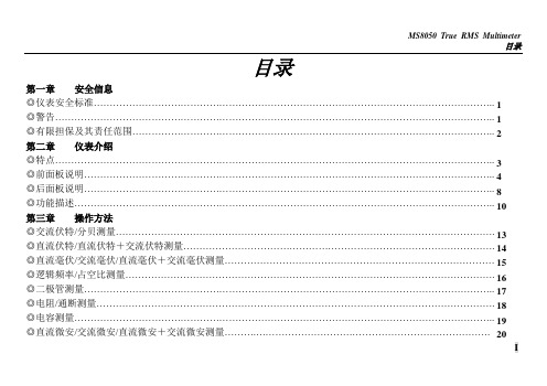
目录目录第一章 安全信息◎仪表安全标准…………………………………………………………………………………………………………….. ◎警告……………………………………………………………………………………………………………………….. ◎有限担保及其责任范围………………………………………………………………………………………………….. 第二章 仪表介绍◎特点……………………………………………………………………………………………………………………….. ◎前面板说明……………………………………………………………………………………………………………….. ◎后面板说明……………………………………………………………………………………………………………….. ◎功能描述………………………………………………………………………………………………………………….. 第三章 操作方法◎交流伏特/分贝测量...................................................................................................................... ◎直流伏特/直流伏特+交流伏特测量................................................................................................. ◎直流毫伏/交流毫伏/直流毫伏+交流毫伏测量.................................................................................... ◎逻辑频率/占空比测量................................................................................................................... ◎二极管测量................................................................................................................................ ◎电阻/通断测量............................................................................................................................ ◎电容测量................................................................................................................................... ◎直流微安/交流微安/直流微安+交流微安测量.. (I)1 123 8 10 13 14 15 16 17 18 19 204目录◎直流毫安/交流毫安/直流毫安+交流毫安测量………………………………………………………………………… ◎直流安培/交流安培/直流安培+交流安培测量………………………………………………………………………… ◎线性频率测量………….…………………………………………………………………………………………..…….. ◎相对值测量………………………………………………………………………………………………………..……… ◎最大值/最小值/最大值 - 最小值测量…………………………………………………………………..……………. ◎数据保持…………………………………………………………………………………………………………..……… ◎数据存储与回放………………………………………………………………………………………………….……… ◎与计算机RS -232C 口的连接………………………………………………………………….……………………… 第四章 技术指标◎一般特性…………………………………………………………………………………………………………..……… ◎量程和精度………………………………………………………………………………………………………………. 第五章 维护◎更换保险丝………………………………………………………………………………………………………………. ◎仪表校准………………………………………………………………………………………………….………………. ◎其它……………………………………………………………………………………………………….……..………..II21 22 24 26 31 32 32 23 24 24 24 25 27第一章安全信息第一章仪表安全标准这款数字多用表是根据国际电工安全标准IEC1010-1对电子测试仪器和手持式数字多用表的安全要求而设计制造的。
蓝牙模块的工作方式全面分析
蓝牙模块的工作方式全面分析一、广播模式蓝牙模块被设置成beacon广播模式,被作为蓝牙基站或信标使用,可以用来推送信息使用。
蓝牙模块工作在beacon广播模式二、主从模式蓝牙模块通信是指两个蓝牙模块或蓝牙设备之间进行通信,进行数据通信的双方一个是主机,一个是从机。
主机是指能够搜索别人并主动建立连接的一方,从机则不能主动建立连接,只能等别人连接自己。
蓝牙4.0模块由于协议限制,一个蓝牙模块的当前状态只能处于其中的一种,要么主机,要么从机。
支持主从模式的蓝牙模块是指能够在主机模式和从机模式之间切换,可以选择工作在主机模式下,也可以选择工作在从机模式下。
三、主从一体模式支持主从一体的的蓝牙模块允许蓝牙模块同时作为主设备和从设备。
举一个家庭自动化的例子。
比如如下场景:一个家庭有小宝宝,父母想要密切监视他们家的空气质量。
他们购买了多个传感器散布在房间周围,中央显示屏显示空气质量,这是本地的解决方案。
如果窗户意外地打开,父母在楼上可能听不到中央单位的警报报警。
主从一体多角色的蓝牙模块可以避免这种情况,传感器数据不再限于在本地显示。
现在可以在系统中连接智能手机,并且可以在云端收集数据。
家长可以在中央单元和智能手机上查看空气过敏原警告,增加他们孩子的保护。
蓝牙模块工作在主从一体模式在这个场景中,蓝牙模块MS50SFA使用了主从一体功能。
在中央显示单元中,MS50SFA工作在主从一体模式,用作主机收集并显示来自空气传感器节点(外围设备)的数据,同时作为从机将传感器数据或警报中继到作为BLE主机的智能手机。
四、扫描模式蓝牙模块工作在扫描模式是指能够扫描周围工作在从机模式或者beacon模式的蓝牙模块。
蓝牙模块工作在扫描模式内嵌蓝牙模块MS50SFA1的蓝牙MAC地址扫描设备充当主机角色,扫描周边设备,根据广播名称过滤,筛选出周边信号最强的设备,获取MAC地址;再进一步上传,通过标签打印机打印出符合要求的二维码。
五、连接模式蓝牙模块工作在连接模式是指两个蓝牙模块一主一从连接进行数据传输。
- 1、下载文档前请自行甄别文档内容的完整性,平台不提供额外的编辑、内容补充、找答案等附加服务。
- 2、"仅部分预览"的文档,不可在线预览部分如存在完整性等问题,可反馈申请退款(可完整预览的文档不适用该条件!)。
- 3、如文档侵犯您的权益,请联系客服反馈,我们会尽快为您处理(人工客服工作时间:9:00-18:30)。
产品规格书PRODUCT SPECIFICATION深圳云里物里科技股份有限公司VersionV4.1发布时间2018-04-25MODEL NO/DESCRIPTION 产品名称:蓝牙模块MS50SFA1C产品型号:MS50SFA1C版本说明目录版本说明 (2)1.概述 (4)2.应用领域 (5)3.电气参数 (5)4.模块尺寸图 (6)5.引脚定义 (6)6.模块配置 (7)6.1透传模块出厂默认值 (7)6.2蓝牙服务UUID (7)6.3UUID描述 (7)6.4工作模式 (7)6.5模块应用示意图 (8)7.透传数据【服务UUID:0xFFF0】(APP端) (8)8参数设置说明 (8)9.模块测试 (112)10.支持的设备 (14)11.PCB设计说明 (145)12.注意事项 (15)13.包装信息 (155)14.质量保证 (166)1.概述MS50SFA1C串口模块采用nRF52810芯片,通过UART(串口)操作可以实现模块与手机之间数据传输。
本模块从模块,具有命令控制可以修改模块的广播名称,修改广播间隔和连接间隔。
使用该模块用户可以快速把数据以蓝牙方式进行传输。
正面反面产品特征远距离:10-60米(空旷环境)BLE协议栈深度优化,睡眠功耗1uA以下传输速率最块可达7Kbps支持串口指令配置支持Android4.3+,7+无需MFi2.应用领域该模块主要用于短距离的数据无线传输领域。
可以方便的和PC机的蓝牙设备相连,也可以与智能手机之间的数据互通。
避免繁琐的线缆连接,能直接替代串口线。
※健身器材设备,如跑步机,健身器等※医疗器械设备,如脉博测量计,心率计等※家用休闲设备,如遥控器,玩具等※办公用品设备,如打印机,扫描仪等※商业设备,如收银机,二维码扫描器等※手机外设配件,如手机防丢器等※汽车设备,如汽车维修仪等※其它人机交互设备3.电气参数参数测试值备注工作电压 1.8-3.6V直流工作频率2400-2483MHz可编程频率误差+/-20KHz Null发射功率-40~+4dBm可调整接收灵敏度-96dBm Null接收电流 4.6mA标准模式发射电流 4.6mA发射功率为0dBm时睡眠功耗1uA以下Null遥控距离10-60米BER<0.1%,空旷天线50ohm Null模块尺寸16*12*2mm Null存储大小192KB4.模块尺寸图5.引脚定义引脚名称引脚定义功能描述备注VCC 电源正极GND 电源负极P0.04BRX 串口(UART)接收蓝牙模块的RX P0.09BTX 串口(UART)发送蓝牙模块的TXP0.17SLP 睡眠/唤醒睡眠为高电平(或悬空),唤醒为低电平P0.11LED1指示灯低电平有效,睡眠状态(灭灯)、空闲状态(一秒闪烁一次)、工作状态(常亮)空闲状态:只广播;工作状态:连接P0.18BTDATA模块发送数据输入信号作为数据发送请求(用来唤醒模块)0:主机有数据发送,模块将等待接收来自主机的数据,此时模块不睡眠1:主机无数据发送,或主机数据发送完6.模块配置6.1透传模块出厂默认值模块角色:从模块模块名称:Minew_V4模块串口波特率:9600bps,8N1广播时间:1s最小连接周期:10ms;最大连接周期:1s发射功率:0dBm6.2蓝牙服务UUID透传服务UUID:FFF0透传接收UUID:FFF1透传发送UUID:FFF26.3UUID描述透传服务:蓝牙转串口透传服务透传接收:以notify方式转发串口输入的数据发送给主设备;透传发送:Write方式接收主设备发来的BLE数据。
将通过串口输出接收到的BLE数据6.4工作模式命令模式未连接时,串口输入的所有数据均视为命令。
模块蓝牙广播,等待被主机连接。
被主机连接后,进入透传模式。
透传模式所有数据的输入视为透传数据,模块将通过蓝牙转发给主机端。
6.5模块应用示意图7透传数据【服务UUID:0xFFF0】(APP端)特征值UUID 可执行的操作字节数默认值备注FFF1notify20无从串口收到输入的数据将会在此通道产生通知发给连接设备说明:串口输入转发到蓝牙输出。
如果打开了通道的通知使能开关,主CPU通过串口向模块发送的合法数据后,将会在此通道产生一个notify通知事件,APP可以直接在回调函数中进行处理和使用FFF2write20无写入的数据将会从串口输出说明:蓝牙输入转发到串口输出。
APP通过BLEAPI接口向此通道写操作后,数据将会从串口输出。
(一次不能超过20个字节,否则会丢失数据) 8参数设置及注意事项说明(1)断开状态的字串会当成指令进行解析并执行,然后输出执行结果,"TTM:OK\r\n\0"或"TTM:ERP\r\n\0"等。
连接模式的串口数据包,将被视为透传数据。
(2)设置参数“BTDATA”管脚要拉低(BTDATA=0),设置完参数需要发送“TTM:RST-SYS”或者重新上电新的参数才会生效。
(3)根据需求,上电之前请给P0.18与P0.16对应所需功能的电平,防止悬空输入引脚静电干扰。
(4)命令模式下需要发送的ASCII必须转换为十六进制发送,否则手机端无法识别,如模块的名字等。
8.1设置模块的名字向串口发送以下字串,"-"以后为模块名,长度为16个字节以内,不能为空,如:"TTM:REN-"+Name(Name为十六进制)会从串口收到"TTM:OK\r\n\0"确认设置成功如果指令格式不对,则会返回:"TTM:ERP\r\n\0"8.2设置广播时间向串口发送以下字串,设置模块的广播周期,T=X*100ms,如:"TTM:ADP-X"(X为十六进制)其中X的范围为:1到20。
会从串口收到"TTM:OK\r\n\0"确认设置成功如果指令格式不对,则会返回:"TTM:ERP\r\n\0"广播周期设定掉电保存,重启模块后,模块将按照新的广播周期进行广播备注:广播间隔越大,功耗越低。
最大广播间隔2S8.3设置连接间隔设定向串口发送以下字串,设定BLE连接间隔,T=X*10ms,如:"TTM:CIT-X"(X为十六进制)其中X的范围为:2到100。
会从串口收到"TTM:OK\r\n\0"确认设置成功如果指令格式不对,则会返回:"TTM:ERP\r\n\0"8.4设置发射功率参数向串口发送以下字串,设置相应的发射功率,单位dBm,如:"TTM:TPL-X"(X为十六进制)其中X的范围为:0到7。
分别代表"-40","-20","-16","-12","-8","-4","0","4"。
会从串口收到"TTM:OK\r\n\0"确认设置成功如果指令格式不对,则会返回:"TTM:ERP\r\n\0"8.5波特率设定向串口发送以下字串,-后参数为新波特率,如:其中X的范围为:0到4。
分别代表"9600","19200","38400","57600","115200"会从串口收到"TTM:OK\r\n\0"确认设置成功如果指令格式不对,则会返回:"TTM:ERP\r\n\0"8.6获取物理地址MAC向串口发送以下字串,如:"TTM:MAC-?"会从串口收到:"TTM:MAC-xxxxxxxxxxxx\r\n\0"确认读取成功字串后面"xxxxxxxxxxxx"为6字节模块蓝牙地址如果指令格式不对,则会返回:"TTM:ERP\r\n\0"8.7获取应用程序固件版本VERSION向串口发送以下字串,如:"TTM:VER-?"会从串口收到:"TTM:VER-xxxx\r\n\0"确认读取成功字串后面"xxxx"为4字节模块蓝牙固件版本号。
如果指令格式不对,则会返回:"TTM:ERP\r\n\0"8.8模块软复位向串口发送以下字串:"TTM:RST-SYS"会迫使模块软复位一次如果指令格式不对,则会返回:"TTM:ERP\r\n\0"8.9自定义广播内容向串口发送以下字串,自定义广播内容,如:"TTM:ADD-"+Data(Data为字符)其中Data为准备附加的广播的数据,Data为字符型,长度0<L<=16会从串口收到"TTM:OK\r\n\0"确认设置成功如果指令格式不对,则会返回:"TTM:ERP\r\n\0"例如设为“TTM:ADD-Minew"广播数据为:4D696E65778.10定义产品识别码"TTM:PID-"+Data(Data为十六进制)其中Data为两个字节的产品识别码,范围0x0000~0xFFFF(L=2,A\B\C\D\E\F必须为大写)。
会从串口收到"TTM:OK\r\n\0"确认设置成功如果指令格式不对,则会返回:"TTM:ERP\r\n\0"Data为十六进制数,例如发送"TTM:PID-5588”广播的头两个字节为0x55、0x888.11模块恢复出厂设置向串口发送以下字串:"TTM:RST-FAC"再发送"TTM:RST-SYS"会迫使模块恢复出厂设置如果指令格式不对,则会返回:"TTM:ERP\r\n\0"9.模块测试9.1通过PC串口修改指令的操作步骤第一步:将USB线连接开发板和电脑USB口。
(如果没安装串口驱动,需先安装)第二步:打开串口助手软件第三步:选择对应的串口,如图1第四步:配置串口参数,如图2图1图2图3第五步:打开串口,如图3第六步:将模块串口使能(即BTDATA =0,SLP=0)。
第七步:按上面所介绍的指令修改你所要修改的参数即可。
9.2透传操作测试1、模块连接好上电后打开软件,如图42、搜索模块,如图53、连接模块,如图6图4图5图64、打开串口,向手机发数据,如图75、手机Minew 串口助手接收数据,如图8图7图86、手机Minew 串口助手向串口发数据,如图97、串口接收数据,如图10图9图1010.支持的设备支持设备系统支持设备型号iOS 7.0及以上iPhone 4S,iPhone 5,iPhone 5S,iphone 6,iPhone 6p,iPad 3,iPad mini,iPad air 等Android 4.3及以上Samsung Galaxy S III,Galaxy S IV,Galaxy Note II,Galaxy Note III and Motorola Razr,HTC One 等11.PCB 设计说明天线部分不能有金属布线,最好做镂空处理,或安置在PCB 板边缘。