The Performance Evaluation of the Integration of Inertial Navigation System and Global Nav
原子陀螺研究进展及展望
收稿日期:2022-10-03基金项目:上海航天先进技术联合研究基金(USCAST2019 23);上海交通大学“深蓝计划”基金项目(SL2021ZD202);“十三五”装备预研领域基金项目(重点)(61405170103)引用格式:骆曼箬,李绍良,黄艺明,等.原子陀螺研究进展及展望[J].测控技术,2023,42(10):1-10.LUOMR,LISL,HUANGYM,etal.ReviewandProspectofAtomicGyroscopeDevelopment[J].Measurement&ControlTech nology,2023,42(10):1-10.原子陀螺研究进展及展望骆曼箬1,李绍良2,黄艺明1,张 弛1,吴招才3,刘 华1(1.上海交通大学电子信息与电气工程学院,上海 200240;2.上海航天控制技术研究所,上海 201109;3.自然资源部第二海洋研究所,浙江杭州 310012)摘要:原子陀螺是基于量子物理原理和量子技术的新型高性能惯性传感器,在国防、军用以及民用等领域均具有广阔的应用前景,已成为国内外惯性技术领域的研究热点。
目前原子陀螺主要分为核磁共振陀螺、无自旋交换弛豫陀螺和原子干涉陀螺,分别对它们的研究历程和现状进行了详细介绍,并对原子陀螺的未来发展趋势方向进行了展望,最后针对国内原子陀螺技术研究提出了一些思考。
关键词:原子陀螺;惯性导航;组合陀螺系统;芯片级陀螺中图分类号:V241 文献标志码:A 文章编号:1000-8829(2023)10-0001-10doi:10.19708/j.ckjs.2023.01.210ReviewandProspectofAtomicGyroscopeDevelopmentLUOManruo1牞LIShaoliang2牞HUANGYiming1牞ZHANGChi1牞WUZhaocai3牞LIUHua1牗1.SchoolofElectronicInformationandElectricalEngineering牞ShanghaiJiaoTongUniversity牞Shanghai200240牞China牷2.ShanghaiInstituteofSpaceflightControlTechnology牞Shanghai201109牞China牷3.SecondInstituteofOceanography牞MNR牞Hangzhou310012牞China牘Abstract牶Atomicgyroscopeisanewhigh performanceinertialsensorwhichisnewlydevelopedbasedonquantumphysicsprinciplesandquantumtechnology.Ithasbroadapplicationprospectsinnationaldefense牞militaryandcivilfields牞andhasbecomearesearchhotspotinthefieldofinertialtechnologyathomeanda broad.Atpresent牞atomicgyroscopesaremainlydevidedintonuclearmagneticresonancegyroscope牞spinex changerelaxationfreegyroscopeandatom interferometergyroscope.Theresearchhistoryandcurrentsituationofthesegyroscopesareintroducedindetail牞andthefuturedevelopmenttrendofatomicgyroscopesisprospec ted.Finally牞somethoughtsondomesticresearchofatomicgyroscopesareputforward.Keywords牶atomicgyroscope牷inertialnavigation牷combinatorialgyroscopesystem牷chip scalegyroscope 陀螺仪是惯性导航系统中的核心器件,用于测量载体运动的角加速度。
基于位置观测信息的Davenport四元数DVL_标定方法

第45卷 第11期2023年11月系统工程与电子技术SystemsEngineeringandElectronicsVol.45 No.11November2023文章编号:1001 506X(2023)11 3640 09 网址:www.sys ele.com收稿日期:20220930;修回日期:20221129;网络优先出版日期:20230310。
网络优先出版地址:https:∥kns.cnki.net/kcms/detail/11.2422.TN.20230310.1049.002.html基金项目:国家自然科学基金(42004067)资助课题 通讯作者.引用格式:唐洪琼,许江宁,史文策,等.基于位置观测信息的Davenport四元数DVL标定方法[J].系统工程与电子技术,2023,45(11):3640 3648.犚犲犳犲狉犲狀犮犲犳狅狉犿犪狋:TANGHQ,XUJN,SHIWC,etal.DavenportquaternionDVLcalibrationmethodbasedonpositionobservationinformation[J].SystemsEngineeringandElectronics,2023,45(11):3640 3648.基于位置观测信息的犇犪狏犲狀狆狅狉狋四元数犇犞犔标定方法唐洪琼1,许江宁1,史文策1,2,何泓洋1,李方能1, (1.海军工程大学电气工程学院,湖北武汉430033;2.中国人民解放军91321部队,浙江金华322000) 摘 要:多普勒计程仪(Dopplervelocitylog,DVL)能够实时为捷联惯性导航系统(strapdowninertialnavi gationsystem,SINS)提供外部速度辅助信息,准确稳定的DVL标定工作对提升SINS/DVL组合导航系统的性能具有重要意义。
为有效解决此问题,提出了一种基于位置观测信息的Davenport四元数标定方法。
导航制导与控制英语作文

导航制导与控制英语作文英文回答:Navigation Guidance and Control.Navigation guidance and control are critical components of any autonomous system, enabling it to determine its current position, plan a path to its destination, and execute that path accurately. These systems are used in a wide variety of applications, from self-driving cars to spacecraft.Navigation.Navigation is the process of determining the current position of a system. This can be done using a variety of sensors, such as GPS, inertial navigation systems (INS), and odometers. GPS is a satellite-based system that provides accurate positioning information, but it can be unreliable in certain environments, such as urban areas orindoors. INS uses accelerometers and gyroscopes to measure the system's motion and calculate its position, but it can drift over time. Odometers measure the distance traveled by the system, but they can be inaccurate due to wheel slippage or other factors.Guidance.Guidance is the process of planning a path to a destination. This path can be generated using a variety of algorithms, such as A search, Dijkstra's algorithm, or the Rapidly-exploring Random Tree (RRT) algorithm. These algorithms take into account the system's current position, its destination, and any obstacles in the environment.Control.Control is the process of executing the path planned by the guidance system. This involves actuating the system's control surfaces, such as the steering wheel, throttle, and brakes. Control systems can be designed using a variety of techniques, such as PID control, LQR control, or MPCcontrol. These techniques take into account the system's dynamics and the desired path to generate control inputs that will keep the system on track.中文回答:导航制导与控制。
飞行英语词组

飞行英语词组第一章machine-powered flight 机械动力飞行pressurized cabin 增加座舱civilian aircraft 民用飞机jet propulsion 喷气推进transoceanic flight 跨洋飞行航空器运行aircraft operation平均速度average speed跨大陆飞行transcontinental flight军用飞机military aircraft环球飞行round-the-world flight第二章landing gear 起落架vertical stabilizer 垂直安定面rotating force 旋转力trim tab 配平调整片lifting surface 升力面巡航飞行cruising flight前三点式起落架tricycle gear产生电能generate electrical power单发飞机single-engine airplane 空气流动air flow第三章launch pad 发射台spatial position 空间位置force and moment 力与力矩rotor blade 转子叶片supersonic flow 超音速流风洞wind tunnel质量守恒conservation of mass 流场flow field冲击波shock wave最小马赫数minimum mach第四章static pressure 静压angle of bank 倾斜角rate of turn 转弯率level flight 水平飞行indicator pointer 指示器指针大气压力atmospheric pressure飞行数据flight data姿态指示仪attitude indicator升降速度表vertical speed indicator 飞行员的视线pilot's line of sight第五章propulsion system 推进系统auxiliary power units 辅助动力系统rotating shaft 旋转轴fuel combustion 燃料燃烧piston-driven aircraft 活塞式飞机军用战斗机military fighter巡航速度cruising speed产生推力generate thrust提高燃油效率improve fuel efficiency 导管螺旋桨ducted propeller第六章nose over 拿大顶ground loop 打地转center of gravity 重心tailwheel landing gear 后三点式起落架foot pedal 脚踏板前三点式起落架飞机tricycle landing gear airplane 差动刹车differential braking减震支柱shock strut定向控制directional control起落架报警gear warning horn第七章fly by wire 线传操控Ram Air Turbine 冲压空气涡轮constant-speed propeller 定速螺旋桨selector valve 选择阀门rotary actuator 旋转式作动装置作动筒actuator cylinder安全阀safety valve单动式伺服single acting servo防滑刹车系统anti-skid brake system液压泵hydraulic pump第八章fuel selector valve 燃油选择阀fuel starvation 燃油耗尽float level gauge 浮子液位测量仪refueling system 加油系统boost pump 增压泵负压negative pressure燃油载量fuel load通用航空general aviation燃油控制阀flow valve发动机引气engine bleed air第九章pilot an aircraft 领航radio navigation aids 无线电导航设备aeronautical chart 航图the magnetic variation 磁差inertial navigation systems 惯性导航系统空中营救infight rescue空中交通管制air traffic control最低安全高度minimum safe altitude航向指示器heading indicator信息反馈information feedback第十章radio call 无线电呼叫radiotelephony communication无线电通话radio terminology 无线电术语air miss 危险接近standard phraseology 标准用语商用飞机commercial aircraft危险的后果dangerous consequence复诵放行许可read back the clearance发现错误pick up the error国内航班domestic flight第十一章anti-collision system防撞系统military combat aircraft 军用作战飞机aircraft intercoms 内部通话系统glass cockpit玻璃座舱auto stabilization自动安定飞行操作系统flight control system自动飞行控制automated flight control交通警戒防撞系统Traffic Alert And Collision Avoidance System 雷达高度计radar altimeter发动机监测系统engine monitoring system第十二章inactive runway 未使用的跑道holding areas 等待区departure gate 登机口Terminal Control Center 终端管制中心inbound aircraft 进港的飞机放行许可delivery clearance开始滑行commence taxiing雷达进近radar approach飞行路线flight route飞行高度限制altitude restriction第十三章Aeronautical Information Service (AIS) 航空情报服务Aeronautical Information Circulars (AIC) 航行资料通报data-dependant on-board navigation system 依赖数据的机载导航系统file transfer 文件传输Required Navigation Performance (RNP) 所需导航性能一体化航空情报系列资料integrated aeronautical information package (IAIP)航行通告NOTAM (Notice to Airmen)数据分发data distribution航空情报管理aeronautical information management(AIM)区域导航area navigation(RNAV)第十四章special use airspace 专用空域Visual Flight Rules(VFR)目视飞行规则controlled airspace 管制空域Terminal Radar Service Areas(TRSA)终端雷达服务区lower airspace 低空空域给定航线designated route仪表飞行规则instrument flight rules (IFR)平均海平面高度mean sea level离地高度above ground level双向无线电通信two way radio communication第十五章crew resource making 班组资源管理situation awareness 情景意识decision making 决策first officer 副驾驶walks of life 各行各业人际沟通interpersonal communication飞行安全flight safety任务分析mission analysis驾驶舱通话记录cockpit voice recording组织文化organizational culture第十六章fixed base operator 固定基地运营者clearance delivery 放行许可Precision Approach Radar (PAR) 精密进近雷达Visual Approach Slope Indicator (VASI) 目视进近坡度指示器Approach Lighting System (ALS) 进近灯光系统航站楼terminal building测距仪distance measuring equipment (DME)甚高频全向信标VHF omni-directional range (VOR)仪表着陆系统instrument landing system (ILS)交通流量traffic flow第十七章mutual benefit 互惠互利full-service airline 提供全面服务的航空公司low cost airline 廉价航空hub airport 枢纽机场long-distance route 长途航线航空运营人运行合格证air operator's certificate 航空保险aviation insurance定期航班scheduled flight航空运输服务air transport service地面交通surface traffic第十八章winds aloft 高空风Clear Air Turbulence (CAT) 晴空湍流Pilot Reports (PIREPS) 飞行员报告high wind 疾风temperature gradient 温度梯度连锁反应chain reaction耗油量fuel consumption终端区域terminal area风切变wind shear对流天气convective weather。
基于AR建模的组合导航系统渐变故障双阈值检测方法

第29卷第1期中国惯性技术学报V ol.29 No.1 2021年2月Journal of Chinese Inertial Technology Feb. 2021 文章编号:1005-6734(2021)01-0133-08 doi.10.13695/ki.12-1222/o3.2021.01.021基于AR建模的组合导航系统渐变故障双阈值检测方法吕旭1,胡柏青1,戴永彬2,高端阳1(1. 海军工程大学电气工程学院,武汉430033;2. 辽宁工业大学电气工程学院,锦州121001)摘要:针对传统残差2χ检测方法在组合导航系统中渐变故障检测率不高的问题,为了及时有效地检测故障信息,提高系统可靠性,提出了一种基于AR量测建模的组合导航系统渐变故障双阈值检测方法。
该方法通过建立无故障条件下量测数据的AR模型,结合卡尔曼滤波模型得到量测预报值进行残差计算,提高故障检测的灵敏度;搭建双阈值检测门限,对误警率和漏警率之间的受污染的量测数据,采用双阈值门限进行分类处理,降低了漏警率对数据可靠性的影响。
避免由于传统残差2χ检测方法因引入观测污染数据,对渐变故障不敏感的问题。
为了验证所提方法的有效性,将该方法应用到SINS/GNSS 组合导航系统中进行仿真实验。
仿真结果表明,所提方法渐变故障检测漏警率较常规残差2χ双阈值检测方法降低69%以上,整体滤波精度提高19%以上,提高了系统的可靠性。
关 键 词:组合导航;残差;AR模型;故障检测中图分类号:U666.11 文献标志码:AThe dual-threshold detection method of mitigating fault of integratednavigation system based on AR modelingLYU Xu1, HU Baiqing1, DAI Yongbin2, GAO Duanyang1(1. College of Electrical, Naval University of Engineering, Wuhan 430033, China;2. School of Electrical Engineering, Liaoning University of Technology, Jinzhou 121001, China)Abstract: Aiming at the problem that the traditional residual chi-square detection method is not high in the detection rate of gradual faults in the integrated navigation system, a double threshold gradual fault detection method based on AR measurement modeling is proposed to detect the fault information timely and effectively and improve the reliability of the system. In the method, the AR model of the measured data is established under the no-fault condition, and the residual calculation of the measured prediction value is obtained by the Kalman filter model, so as to improve the sensitivity of fault detection. At the same time, a double threshold detection threshold is set up, and the contaminated observation datas between the false alarm rate and the missing alarm rate are classified and processed by the double threshold, which reduces the influence of the missing alarm rate on data reliability and avoids the problem that the traditional residual chi-square detection method is insensitive to gradual fault due to the introduction of observation pollution data. In order to verify the effectiveness of the proposed method, the method is applied to the SINS/GNSS integrated navigation system for simulation experiments. The simulation results show that the detection missing alarm rate of the proposed method is reduced by more than 69%, and the overall filtering accuracy can be increased by more than 19%, which improves the reliability of the system.Key words: integrated navigation; residual; AR model; fault detection收稿日期:2020-10-27;修回日期:2021-01-10基金项目:国家自然科学基金(61703419,61873275)作者简介:吕旭(1990—),男,博士研究生,从事组合导航研究。
dfs-service-组合导航_武大牛小骥_201412科大share
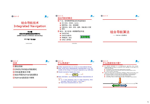
什么是滤波?
A filter separates the mix of two or more distinct things Filter must know distinguishing characteristics (e.g. the model) of the things it’s trying to separate (e.g. estimate)
GNSS/INS 组合模式 ——紧组合
Using a Centralized Filter (closed Loop)
Feedback is applied from the integration filter to the INS mechanization equations. Results of previous step are used to minimize approximation error.
Kalman Filter
Inertial - Aiding Error Error
8
7
组 合导航模式
9
GNSS/INS 组合模式
Decentralized Filter (Loosely-couple)
Open loop Closed loop (feedback)
GNSS/INS 组合模式 ——松组合
Using a Decentralized Filter (Open Loop)
GPS solution is performed first using a GPS Kalman filter then the filtered position and velocity are sent as input to the INS Kalman filter. No feedback is performed.
Integrated_Camera-Based_Navigation
INTEGRATED CAMERA-BASED NAVIGATIONBrita Helene Hafskjold1,2, Bjørn Jalving1, Per Espen Hagen1 and Kenneth Gade11 Norwegian Defence Research Establishment (FFI)P.O. Box 25N-2027 KjellerNorway2 Center for Technology at Kjeller (UniK)P.O. Box 70N-2027 KjellerNorwaybritah@unik.no, Bjorn.Jalving@ffi.no, Per-Espen.Hagen@ffi.no, Kenneth.Gade@ffi.no AbstractThis paper presents an integrated INS (Inertial Navigation System) and camera-based navigation system. The camera-based navigation system provides position measurement aiding to the INS. This is an alternative to the conventional GPS (Global Positioning System) aided INS. The system is intended for UAVs (Unmanned Aerial Vehicles) and long range missiles.The basic principles of camera-based navigation are presented. The Kalman filter based integration of INS and camera-based navigation is discussed. Total system simulation results are shown together with INS simulations for comparison. Finally, a brief overview of factors that improve the navigation accuracy is presented.1. IntroductionGPS is vulnerable to jamming and other disturbances. Camera-based navigation cannot that easily be disturbed, and an INS is impossible to jam. By combining camera-based navigation and INS in an integrated navigation system, we obtain a system that unites:• the precise measurement of high frequency motion that the INS delivers, and• the low position drift rate that the camera-based navigation offers.The system contains three types of sensors:• A camera (strapdown), capturing the terrain. The raw image data are fed into an image-processing algorithm, the output of which is a set of recognisable points in the image. The camera-based navigation is described in more detail in Chapter 3.• An IMU (Inertial Measurement Unit) containing three gyroscopes and three accelerometers.• An altimeter (e.g. an air pressure transmitter).An existing digital elevation map is also used.This work is based on the camera-based navigation found in Hagen [1] and the INS work in Gade [2]. The contribution of this work is the integration of these two systems. Two textbooks on INS which can be recommended are Britting [3] and Titterton & Weston [4].2. Mathematical notationThe mathematical notation used in this paper is:p image token I inertial co-ordinate systeml landmark L local co-ordinate systemxˆestimate of x C camera co-ordinate systemx~measurement of x B body co-ordinate systemx k value of x at time k E earth co-ordinate systemx A vector x decomposed in co-ordinate system A P picture co-ordinate systemThe co-ordinate systems used in this paper are depicted in Figures 1 and 2:Figure 1 Co-ordinate systems B, I, E and L.Figure 2 Co-ordinate systems B, C and P. 3. Principles of camera-based navigationCamera-based navigation has traditionally been used to navigate across a pre-mapped terrain, which means that a flight must be performed over the specific route to pre-collect either easy-to-recognise structures in the picture or whole pictures. During the subsequent flights, the camera pictures are compared to these pre-saved pictures, and the position and attitude of the plane can be calculated.Our system does not require pre-mapping. The easy-to-recognise objects must be chosen, and their ground position determined, during flight. This is done by the image processing routine, which chooses an image token as a point in the image that will be easy to recognise in the next image in the sequence. These image tokens' movements in the image give us informationabout the topography of the depicted landscape (and the vehicle movement). The use of this information, which is dependent on the position of the camera relative the terrain, together with an elevation map, gives us a method that is quite different from the traditional "optical flow" algorithm. The image processing routine is fully explained in Hagen [1]. A landmark is a point on the terrain surface that corresponds to an image token. In our system, INS position and attitude are used to calculate the landmark position, as illustrated in Figure 3.Figure 3f = focal point of the camera, p i = image token no. i, l i = landmark no. iThe image tokens will remain in the image as long as the corresponding landmarks are in the line-of-sight of the camera, i.e. within the camera aperture angle. When an image token disappears from the image, a new landmark must be chosen. Image tokens can also be lost because of changes in perspective, where a landmark can be hidden behind a hill, scene changes (such as cars driving down a road), or due to mist or other circumstances that renders the image tokens unrecognisable in the next image. Because we want to keep a constant number of landmarks, a new landmark is chosen each time an image token is lost. This is conducted by the image processing routine, as described above.4. Integration of INS and camera-based navigationThe integrated system works as follows: At each timestep, the INS computes an estimate of the vehicle position and attitude. The integration with the camera-based navigation is carried out by using these estimates together with the position of the landmarks to calculate predicted positions of the image tokens. The difference between these predicted positions and the measured positions of the image tokens is used by an error-state Kalman filter to estimate the INS errors, as illustrated in Figures 4 and 5.Figure 4 The difference between the calculated (Pk 1ˆ+p ) and the true (P k 1+p ) image tokenposition is a function of the INS errorFigure 5 The difference between the calculated (P k p ˆ) and the measured (P k p ~) image tokenposition is used as the Kalman filter measurement.Figure 6 shows the total system structure. The camera-based navigation uses themeasurements from the INS and the altimeter to calculate the image token positions in the next image, as illustrated in Figure 4.Figure 6 Total system structure) 1+k t ) at time 1k k t +Figure 7 shows a more detailed total structure picture. The rightmost box represents the image processing routine (explained in Hagen [1]), which measures the position of the image tokens in the next image. The Kalman filter uses the INS attitude and position estimates in its system matrix. The Kalman filter's estimate of the INS attitude and position error is used to reset the INS for each new image in the video stream.Figure 7 Main algorithm of the camera-based navigation5. Simulation resultsThe total system has been simulated with the IMU quality, terrain and trajectory given in Chapter 5.1. Chapter 5.2 shows the INS drift (corresponding to the IMU quality in Table 1) and two simulations are shown and briefly discussed in Chapter 5.3. A description of system behaviour is given in Chapter 5.4.5.1 Simulation assumptionsWe have made no assumptions as to the type of aerial vehicle used in our simulations. Because our system use the navigation equations for the IMU/INS, the only vehicle parameters used are speed, position and attitude.5.1.1 IMU qualityTable 1 shows the accuracy of the >10 nmi/h IMU used in the simulations.GYROSCOPES ACCELEROMETERSMisalignment error 0.1 mrad (1σ) Misalignment error 0.1 mrad (1Scale factor error 50 ppm (1σ) Scale factor error 100 ppm (11º/h (1σ) Bias error 1 mg (1σ) Angular random walk 0.1º/h Velocity random walk negligible Table 1 IMU quality5.1.2 Terrain and trajectoryFigure 8 shows the terrain and trajectories used in the simulations in this paper.Figure 8 Simulation trajectories60005000400030002000100010002000-1000-2000050010001500200025003000The UAV starts out at the intersection between the prime meridian and equator, flying straight north with a speed of 50 m/s. The vehicle height is 1000 meters above mean sea level in simulation 1 and 3000 meters above mean sea level in simulation 2.5.2 INS driftFigure 9 shows a simulation of the free inertial performance of the INS. The simulation is performed with the IMU quality and trajectory as described in Chapter 5.1.Figure 9 INS positioning error5.3 Total system accuracyIn this chapter, the simulations use the same IMU quality and trajectory as in Chapter 5.2, but the INS is now aided by the camera-based navigation.The total system accuracy depends on numerous parameters. In order to illustrate the influence of such parameters on the total system behaviour, only one parameter, namely the vehicle height above the terrain, is changed from simulation 1 to simulation 2. The rest of the main simulation parameters are:Picture frequency: 25 Hz Measurement noise: 0.8 pixelsPicture size: 500×500 pixels Altimeter error std. deviation: 1 mCamera aperture angle: 136°Number of landmarks: 12Camera mounting: Downward, such that the x axisof co-ordinate system C and the z axis of co-ordinate system B are parallelThe influence on the total system behaviour of altering these parameters is briefly discussed in Chapter 5.4.Figure 10 shows simulation 1, where the vehicle height is 1000 meters above mean sea level.Figure 10 Total system position error of simulation 1. Dotted: true positioning error.Solid: the Kalman filter estimate of the position error.In Figure 10 the Kalman filter's estimate of the position error is close to zero, making the estimation error the only visible graph. This is due to the reset of INS at each timestep (which in this simulation equals 25 times per second). The mathematical function depicted in Figure 4 shows that the error of the predicted position of an image token is a function of the INS error developed in the time period between the two images. By resetting the INS for each new image, we can guarantee the total INS error to be optimally close to the INS error developed in the time period between two images.Simulation 2, where the vehicle height is 3000 meters above mean sea level, is shown in figure 11.Figure 11 Total system position error of simulation 2. Dotted: true positioning error.Solid: the Kalman filter estimate of the position error.Figure 11 shows improved position accuracy compared to Figure 10. Increasing the distance between the vehicle and the terrain increases the time that each landmark is present in the picture. With a constant picture frequency, this gives more measurements of each landmark before we loose it.Both simulations show more drift in the cross-track direction (east) than in the along-track direction (north). The heading uncertainty is normally the main drift source, giving drift of first order across the trajectory, and of second order along the trajectory.5.4 System behaviourIncreasing the picture frequency provides more measurements of each landmark before its corresponding image token is lost (i.e. before it is out of sight of the camera). With all other parameters unchanged, this reduces the influence of the measurement noise, thereby increasing the navigation accuracy.Increasing the number of pixels in the image increases the picture resolution, thereby decreasing the measurement noise.Enlarging the camera aperture angle increases the time period that each image token is present in the picture, thereby allowing more measurements of each landmark, which would improve the total system accuracy. Increasing the camera aperture angle however, results in a wider angle covered by each pixel, so that the measurement noise (in pixels) corresponds to a larger area on the ground, which decreases the total system accuracy.Changing the camera orientation from pointing straight downward to 45° forward reduces the system drift. This increases the time that each landmark is in the line-of-sight of the camera, contributing to an increased number of measurements of each landmark.A curvy terrain beneath the vehicle improves the geometrical distribution of the landmarks, making it easier to solve ambiguities such as roll vs. position in the cross-track direction and pitch vs. position in the along-track direction. Simulations in Hafskjold [5] show that this improves the camera-based navigation performance.6. ConclusionsA method for aiding an INS with a camera-based navigation system has been proposed.This paper has discussed the effect of system parameters on the navigation performance. Hafskjold [5] showed that the total system accuracy can be improved by:• Increased picture frequency• Increased number of landmarks (this requires more computing power, since each new landmark adds 3 elements to the Kalman filter state vector).• Decreased picture measurement noise (e.g. by avoiding areas covered in mist or smoke, decreasing the camera aperture angle or increasing the picture resolution by increasing the number of pixels in the image).• Increased time period in which each image token is present in the image (e.g. by reducing the vehicle speed, increasing the vehicle height above the terrain or increasing the camera aperture angle).• Increased geometrical distribution of the landmarks (e.g. by choosing a curvy terrain or by reducing the vehicle height above the terrain).The INS system in the simulations has been of the >10 nmi/h class, which is usually found in missiles, UAVs etc. Military and civilian aeroplanes are usually equipped with the more accurate 1 nmi/h type of systems. A 1 nmi/h based system will have higher accuracy or alternatively put less demand on the camera-based navigation system aiding.References:[1] P. E. Hagen, "Navigation by images", Modelling, Identification and Control, vol. 14,no.3, 1993.[2] K. Gade, Integrering av treghetsnavigasjon i en autonom undervannsfarkost (inNorwegian), Institutt for teknisk kybernetikk, Norwegian University of Science andTechnology, Norway, 1997.[3] K. R. Britting, Inertial navigation systems analysis, Wiley Interscience, 1971[4] D. H. Titterton and J. L. Weston, Strapdown inertial navigation technology, PeterPeregrinus Ltd, Herts, U.K., 1997.[5] B. H. Hafskjold, Integrert bildebasert navigasjon (in Norwegian), FFI/Rapport-99/02703,Norwegian Defence Research Establishment, Norway, 1999.。
无线电通话用语
民航总局空管局二〇〇三年八月一日1 范围本标准规定了民用航空空中交通无线电通话用语(英语和汉语)的规范表述方法,以及飞行各阶段无线电通话的有关内容。
本标准适用于民用航空空中交通的无线电通话。
2.1 术语和定义下列术语和定义适用于本标准。
2.1.1 正切abeam某定位点、地点或目标在航空器左侧或右侧与航空器航迹成大约90°角。
注:正切是指一般性位置,不是精确点。
2.1.2 机场aerodrome供航空器起飞、降落、滑行、停放以及进行其他活动使用的划定区域,包括附属的建筑物、装置和设施。
2.1.3 机场管制服务aerodrome control service为机场交通提供的空中交通管制服务。
2.1.4 塔台管制室aerodrome control tower为机场交通提供空中交通管制服务而设置的单位。
2.1.5 机场活动aerodrome movement航空器在活动区的活动。
2.1.6 机场运行最低标准aerodrome operating minima机场上可供航空器起飞或着陆的最低条件。
注:机场运行最低标准一般以能见度、跑道视程、决断高度、最低下降高度及云底高等条件表示。
2.1.7 机场交通aerodrome traffic在机场机动区内的一切交通以及在机场附近所有航空器的飞行。
在机场附近所有航空器的飞行是指已加入、正在进入和脱离起落航线的航空器的飞行。
2.1.8 机场起落航线aerodrome traffic circuit在机场附近航空器运行所遵循的规定航迹。
2.1.9 航空器识别aircraft identification用于识别航空器身份的一组字母、数字或字母和数字的组合或等同于航空器呼号的代码。
2.1.10 空中交通air traffic一切航空器在飞行中或在机场机动区内的运行。
2.1.11 空中交通管制许可air traffic control clearance空中交通管制单位对航空器在限定条件下运行的批准注:为了方便,空中交通管制许可简称许可,前面可加上滑行、起飞、离场、加入航路、进近、着陆来指示特定飞行阶段的许可。
惯性导航传感器PHINS资料-003
I-8
Hale Waihona Puke Robust Observation and Checking of External Data
I-10
System Performances and Tests Results ....................................................................... I-11
I.4.6 Conclusion on PHINS Technology .................................................................................. I-13
I.5 Certification ......................................................................................................................... I-14 I.6 Export Regulation ............................................................................................................... I-14 I.7 Warranty............................................................................................................................... I-15 I.8 Customer Support .............................................................................................................. I-16 I.9 Contact................................................................................................................................. I-17
民航英语2测试题及答案
民航英语2测试题及答案一、选择题(每题2分,共20分)1. What is the full form of "ATC" in aviation?A. Air Traffic ControlB. Airline Ticket CounterC. Airport Terminal ComplexD. Air Transport Committee2. The term "VFR" stands for:A. Visual Flight RulesB. Very Fast RunnerC. Vertical Flight RegulationsD. Virtual Flight Route3. Which of the following is not a type of weather phenomenon affecting aviation?A. TurbulenceB. ThunderstormC. Clear skyD. Fog4. The abbreviation "ICAO" refers to:A. International Civil Aviation OrganizationB. International Commercial Airline OrganizationC. International Cargo Airline OrganizationD. International Communication Airline Organization5. What does "RVSM" mean in the context of aviation?A. Reduced Vertical Separation MinimumB. Required Visual Separation MinimumC. Radio Visual Separation MinimumD. Radar Vertical Separation Minimum6. The term "ETD" is commonly used to denote:A. Estimated DepartureB. Electronic Ticketing DeviceC. Emergency Training DrillD. Environmental Testing Device7. Which of the following is not a standard aircraft emergency code?A. PAN-PANB. MAYDAYC. SOSD. ALPHA8. The "PBN" in aviation stands for:A. Performance Based NavigationB. Pilot Boarding NotificationC. Passenger Booking NumberD. Personal Belongings Notification9. "SID" in aviation terminology refers to:A. Standard Instrument DepartureB. Special International DepartureC. Scheduled International DateD. Systematic International Delay10. The "STAR" is a term used to describe:A. Standard Terminal Arrival RouteB. Special Technical Assistance RequestC. Scheduled Time of Arrival RequestD. Systematic Training and Reporting答案:1. A2. A3. C4. A5. A6. A7. C8. A9. A 10. A二、填空题(每空1分,共10分)1. The international distress signal "MAYDAY" is used by pilots to indicate an emergency situation requiring__________.2. The term "runway" in an airport refers to a __________ where aircraft take off and land.3. The "black box" in an aircraft is actually orange and is used to record flight data and __________.4. "CVR" stands for Cockpit Voice Recorder, which is a device used to record the __________ and conversations in the cockpit.5. The "ELT" or Emergency Locator Transmitter is a devicethat helps rescue teams locate an aircraft in __________.答案:1. immediate assistance2. flat surface3. cockpit sounds4. ambient noise5. distress三、简答题(每题5分,共10分)1. What are the three main types of aircraft navigationsystems?- Answer: The three main types of aircraft navigation systems are Inertial Navigation Systems (INS), Global Positioning System (GPS), and Instrument Landing System (ILS).2. Explain the purpose of a "No-Fly Zone".- Answer: A "No-Fly Zone" is an area designated byaviation authorities where the flight of aircraft isprohibited for security or safety reasons. It is establishedto protect airspace over sensitive areas such as military bases, government facilities, or during special events.四、阅读理解(共20分)Read the following passage and answer the questions.Passage:Airlines are constantly looking for ways to improveefficiency and reduce costs. One of the methods they use isthe implementation of "code-sharing" agreements. Code-sharing allows two or more airlines to share the same flight, with each airline selling tickets for that flight under their own flight number. This practice benefits both airlines and passengers, as it can lead to more flight options, better connections, and lower fares.Questions:1. What is the purpose of code-sharing agreements in theairline industry? (5 points)- Answer: The purpose of code-sharing agreements is to improve efficiency, reduce costs, and provide more flight options, better connections, and lower fares.2. How do code-sharing agreements benefit passengers? (5 points)- Answer: Code-sharing agreements benefit passengers by offering more flight options, better connections, and potentially lower fares due to increased competition.3. What are some potential drawbacks of code-sharing agreements for airlines? (10 points)- Answer: While the passage does not explicitly mention drawbacks, potential drawbacks of code-sharing agreements for airlines could include loss。