SMC水流量开关说明书
SMC公司的数字流量传感器说明书
Instruction ManualDigital Flow Switch – Modular type PF3A701H / PF3A702HThe intended use of the digital flow switch is to monitor and display flow information while connected to the IO-Link communication protocol.These safety instructions are intended to prevent hazardous situations and/or equipment damage. These instructions indicate the level of potential hazard with the labels of “Caution,” “Warning” or “Danger.”They are all important notes for safety and must be followed in addition to International Standards (ISO/IEC) *1), and other safety regulations. *1)ISO 4414: Pneumatic fluid power - General rules relating to systems. ISO 4413: Hydraulic fluid power - General rules relating to systems.IEC 60204-1: Safety of machinery - Electrical equipment of machines. (Part 1: General requirements)ISO 10218-1: Manipulating industrial robots -Safety. etc.• Refer to product catalogue, Operation Manual and Handling Precautions for SMC Products for additional information. • Keep this manual in a safe place for future reference.CautionCaution indicates a hazard with a low level of risk which, ifnot avoided, could result in minor or moderate injury.WarningWarning indicates a hazard with a medium level of riskwhich, if not avoided, could result in death or serious injury.DangerDanger indicates a hazard with a high level of risk which, ifnot avoided, will result in death or serious injury.Warning• Always ensure compliance with relevant safety laws and standards.• All work must be carried out in a safe manner by a qualified person in compliance with applicable national regulations.• This product is class A equipment intended for use in an industrial environment. There may be potential difficulties in ensuring electromagnetic compatibility in other environments due to conducted or radiated disturbances.• Refer to the operation manual on the SMC website (URL: https:// ) for more safety instructions.2 Specifications2.1 IO-Link specifications • The IODD configuration file can be downloaded from the SMC website (URL: https:// ).Warning• Special products (-X) might have specifications different from those shown in this section. Contact SMC for specific drawings.Element DescriptionDisplay See belowConnector M12 4-pin connector for electrical connections. Lead wire with M12 connector Lead wire for power supply and outputs. Piping port For piping connections. BodyThe body of the product.3.1 Display• IO-Link specificationORIGINAL INSTRUCTIONSModelsPF3A701H PF3A702H Applicable fluid Air, N 2 Operating fluid temperature0 to 50 o C F l o w Detection method Heating sensor (branch flow) Rated flow range 10 to 1000 L/min 20 to 2000 L/min Set point range Instantaneousflow 10 to 1050 L/min 20 to 2100 L/min Accumulated flow 0 to 999,999,999,990 L Min. resolution Instantaneousflow1 L/min2 L/min Accumulated flow 10 L Accumulated volume per pulse (pulse width = 50 ms) Select from 10 L/pulse and 100 L/pulse Accumulated value hold 2 minutes or 5 minutes P r e s s u r e Rated pressure range 0 to 1.0 MPa Proof pressure 1.5 MPa Pressure loss Refer to the pressure loss graph Pressure Characteristics ±5.0 %F.S. (0 to 1.0 MPa, 0.5 MPa standard) E l e c t r i c a l Power supply voltage 24 VDC ±10% as switch output device21.6 to 30 VDC as IO-Link device Current consumption 150 mA or less Protection Polarity protection A c c u r a c yDisplay accuracy ±3.0 %F.S. Analogue outputaccuracy ±3.0 %F.S.Repeatability ±1.0 %F.S.Temperaturecharacteristics ±5.0 %F.S. (Ambient temp. 0 to 50 o C,25 o C standard)Impact when modular devices are connected ±5.0 %S w i t c h o u t p u tOutput type NPN or PNP open collector output Output mode Select one of output (hysteresis orwindow comparator mode), output for accumulated flow, accumulated pulse output.Switch operation Normal or reversed outputMaximum load current 80 mAMaximum applied voltage (NPN output) 28 VDC as switch output device 30 VDC as IO-Link device Internal voltage drop (Residual voltage) NPN: 1.5 V or less (load current 80 mA) PNP: 2.0 V or less (load current 80 mA)Delay time 3.3 ms or lessvariable at 0 to 60 s / 0.01 step Response time Select from 1 s, 2 s, 5 s.Hysteresis VariableProtection Over current protection A n a l o g u e O u t p u tOutput typeVoltage output: 1 to 5 V (0 to 10 V can be selected), Current output: 4 to 20 mA ImpedanceVoltage output Output impedance approx. 1 kΩ Current outputMax. load impedance 600 Ω Min. load impedance 50 Ω Response timeLinked to response time of switch output(output with digital filter setting)Models PF3A701HPF3A702HE x t . i n p u t Input type Input with no voltage: 0.4 V or less Input mode Select from Reset Accumulated Value, Reset Peak and Reset Bottom valuesTime for input 30 ms or moreD i s p l a y Reference condition Normal or Standard condition Display Display method: LCDNumber of displays: 2 (main display and sub display)Colour (main display): Red and green Display colour (sub display): OrangeDisplay - main display: 5 digits, 7 segment Display - sub display: 6 digits, 7 segment Operation LED OUT LED: Red is ON when output is ONE n v i r o n m e n t a lProtection IP65Withstand voltage 1000 V AC for 1 minute betweenterminals and housing Insulation resistance 50 MΩ between terminals and housing(with 500 VDC megger)Operating temperature range Operation: 0 to 50 o C, Storage: -10 to 60 o C (no condensation or freezing) Operating humidity range Operation, Storage: 35 to 85%RH(no condensation) Piping specification Modular (body size 30)Modular (body size 40)Material in contact with fluid SUS304, Aluminium alloy, PPS, HNBR (Sensor: Pt, Au, Ni, Fe, lead glass (notRoHS compliant), Al 2O 3)Lead wire with connector 3 mWeightBody 350 g400 gLead wire90 gElement DescriptionMain display Displays the instantaneous flow value and error codes. (2 colour display)Operation LED Indicates the output status of OUT.When the output is ON: Orange LED is ON. When the accumulated pulse output mode is selected, the output display will turn off.Sub display Displays the accumulated flow, set value, and peak/ bottom value when in measurement mode.▲ button (UP) Selects the mode and the display shown on theSub display or increases the switch point.S button (SET) Press this button to change the mode and to set a value.▼ button (DOWN) Selects the mode and the display shown on the Sub display or decreases the switch point.Units display (Instantaneous flow) Indicates the flow measurement units currently selected.Units display (Accumulated flow) Indicates the flow measurement units currently selected.IO-Link status indicator light LED is ON when OUT1 is used in IO-Link mode. (LED is OFF in SIO mode)4.1 InstallationWarning•Do not install the product unless the safety instructions have been read and understood.•Use the product within the specified operating pressure and temperature range.4.2 EnvironmentWarning•Do not use in an environment where corrosive gases, chemicals, salt water or steam are present.•Do not use in an explosive atmosphere.•Do not expose to direct sunlight. Use a suitable protective cover. •Do not install in a location subject to vibration or impact in excess of the product’s specifications.•Do not mount in a location exposed to radiant heat that would result in temperatures in excess of the product’s specifications.4.3 Mounting•Never mount the product in a location where it will be used as a mechanical support.•Mount the product so that the fluid flows in the direction indicated by the arrow on the side of the body.•Avoid mounting the product with the display facing upward.•Do not mount the product upside down.•The monitor with integrated display can be rotated. Rotating the display with excessive force will damage the end stop. 4.4 PipingCaution•Before connecting piping make sure to clean up chips, cutting oil, dustetc.•When installing piping or fittings, ensure sealant material does notenter inside the port.•Fit the raised part of the spacer to the recessed part (groove for theraised part) of the product.•Temporarily tighten the retainer A with two hexagon socket head capscrews.•Tighten the two hexagon socket head cap screws with a hexagonalwrench evenly.•Refer to the table below for the screws tightening torque.Applicable modelHex wrench socketnominal sizeTightening torquePF3A701H3 1.2 ±0.05 N•mPF3A702H•The following options are required for coupling with modular F, R, andL combinations. They are separately prepared by the user.Digital flowswitchAircombinationSpacerSpacer withbracketPipe adapterPF3A701H AC30#-D Y300-D Y300T-D E300-#03-DPF3A702H AC40#-D Y400-D Y400T-D E400-#04-D•Refer to the SMC website (URL: https://) for moredetails of options.Caution•Do not apply torsion or bending moment other than the weight of theproduct itself. External piping needs to be supported separately as itmay cause damage. If a moment applied to the equipment isunavoidable during operation, the moment should be lower than themaximum moment shown below. Non-flexible piping like steel tube issusceptible to excessive moment load or vibration. Insert flexible tubesto prevent this.Models PF3A701H PF3A702HMaximum moment (M): N•m 16 19.5Max. moment (M) = Length (L) x Load (F)4.5 WiringCaution•Do not perform wiring while the power supply is ON.•Confirm proper insulation of wiring.•Do not route wires and cables together with power or high voltagecables.The product can malfunction due to interference of noise and surgevoltage from power and high voltage cables. Route the wires of theproduct separately from power or high voltage cables.•If a commercially available switching power supply is used, be sure toground the frame ground (FG) terminal. If the product is connected tothe commercially available switching power supply, switching noise willbe superimposed and the product specifications will not be satisfied.In that case, insert a noise filter such as a line noise filter/ ferritebetween the switching power supplies or change the switching powersupply to the series power supply.Pin numbers ofconnectorWhen used as IO-Link deviceNo. NameWirecolourFunction1 DC(+) Brown 21.6 to 30 VDC2 N.C/Other WhiteNot connected /Analogue output orExternal input3 DC(-) Blue 0 V4 C/Q BlackIO-Link data /Switch output (SIO)5 Function Setting5.1 Function selection modeIn measurement mode, press the SET button for 3 seconds or longer todisplay [F 0].Press the UP or DOWN button to select the function to be changed.Press and hold the SET button for 2 seconds or longer in functionselection mode to return to measurement mode.Refer to the SMC website (URL: https://) for moresetting details.5.1 Default settings∗: Items in brackets are IO-Link specifications.• Flow switch setting and functions • IO-Link functions • Zero cut off functionRefer to the operation manual on the SMC website (URL: https:// ) for setting these functions.Refer to the SMC website (URL: https:// ) for more How to Order details.Refer to the SMC website (URL: https:// ) for details of Outline dimensions..9.1 General MaintenanceCaution• Not following proper maintenance procedures could cause the product to malfunction and lead to equipment damage.• If handled improperly, compressed air can be dangerous.• Maintenance of pneumatic systems should be performed only by qualified personnel.• Before performing maintenance, turn off the power supply and be sure to cut off the supply pressure. Confirm that the air is released to atmosphere.• After installation and maintenance, apply operating pressure and power to the equipment and perform appropriate functional and leakage tests to make sure the equipment is installed correctly.• If any electrical connections are disturbed during maintenance, ensure they are reconnected correctly and safety checks are carried out as required to ensure continued compliance with applicable national regulations.• Do not make any modification to the product.• Do not disassemble the product, unless required by installation or maintenance instructions. • Remove condensate periodically.If condensate enters the secondary side, it can cause operating failure of pneumatic equipment.• Do not use solvents such as benzene, thinner etc. to clean the product. This may damage the surface of the body or erase the markings on the body.Use a soft cloth to remove stains.For heavy stains, use a damp cloth that has been soaked with diluted neutral detergent and fully squeezed, then wipe up the stains again with a dry cloth.• How to reset the product after a power cut or when the power has been unexpectedly removedThe settings of the product are retained from before the power cut or de-energizing.The output condition also recovers to that before the power cut or de-energizing, but may change depending on the operating environment. Therefore, check the safety of the whole system before operating the product.10.1 Limited warranty and Disclaimer/Compliance Requirements Refer to Handling Precautions for SMC Products.This product should not be disposed of as municipal waste. Check your local regulations and guidelines to dispose of this product correctly, in order to reduce the impact on human health and the environment.Refer to or www.smc.eu for your local distributor / importer.URL: https:// (Global) https://www.smc.eu (Europe) SMC Corporation, 4-14-1, Sotokanda, Chiyoda-ku, Tokyo 101-0021, Japan Specifications are subject to change without prior notice from the manufacturer. © 2021 SMC Corporation All Rights Reserved. Template DKP50047-F-085MFunction (Main display) Default Settings (Right sub display) (Main display) (Left sub display) [F 0][rEF ] Select display units [ Std] Standard condition [Uni ] ([Unit]) Units selectionfunction [ L] L/min ([NorP]) Select NPN/PNP ([ PnP]) PNP output [F 1] [oUt ] ([oUt1]) Select output mode[ HYS] Hysteresis mode[ ot ] ([1ot ]) Select switch mode [ P] ([ 1_P]) Normal output[ P] ([P_1 ]) Select input switchoperation[ 500] 500 L/min (PF3A701H) [1000] 1000 L/min (PF3A702H) [ H] ([H_1 ]) Setting of Hysteresis [ 50] 50 L/min (PF3A701H) [ 100] 100 L/min (PF3A702H)([dt1 ]) Delay time setting ([0.00]) 0.00 s [CoL ] Select display colour [ SoG] ([1SoG]) Green when ON Red when OFF (OUT1) ([F 2])[oUt2] Select output mode [ HYS] Hysteresis mode [2ot ] Select switch mode [ 2_P] Normal output [P_2 ] Select input switchoperation [ 500] 500 L/min (PF3A701H) [1000] 1000 L/min (PF3A702H) [H_2 ] Setting of Hysteresis[ 50] 50 L/min (PF3A701H) [ 100] 100 L/min (PF3A702H) [dt2 ] Delay time setting [0.00] 0.00 s [CoL ] Select display colour [1SoG] Green when ONRed when OFF (OUT1)[F 3] [FiL ] Select digital filter[ 1.0] 1 second [F 5] [FnC ] ([FUnC]) Select FUNC (switching analogueoutput/external input)[ oUt] ([AoUt]) Analogueoutput [F10] [SUb ] Select sub display(Line name setting)[ dEF] Default setting [F13] [rEv ] Select Reverse display [ oFF] Reverse display OFF [F14] [CUt ] Select Zero cut-off setting [ 1.0] 1%F.S. cut[F30] [SAv ] ([SAvE]) Accumulated value hold [ oFF] Not stored[F80] [dSP ] ([diSP]) Display OFFmode[ on] Display ON [F81] [Pin ]Security code [ oFF] Not used [F90] [ALL ] Setting of all functions [ oFF] Not used [F96] [Sin ] ([S_in]) Check of input signal [ - - - ] No input signal[F98] [tES ] ([tESt]) Setting ofoutput check[ n] Normal output [F99] [ini ] Reset to the default settings [ oFF] Not used。
SLMC 数显流量开关集成型说明书 - PF2M7##系列

Instruction ManualPF2M7## seriesThe intended use of the digital flow switch is to monitor and display flow information.These safety instructions are intended to prevent hazardous situations and/or equipment damage. These instructions indicate the level of potential hazard with the labels of “Caution,” “Warning” or “Danger.”They are all important notes for safety and must be followed in addition to International Standards (ISO/IEC) *1), and other safety regulations. *1)ISO 4414: Pneumatic fluid power - General rules relating to systems. ISO 4413: Hydraulic fluid power - General rules relating to systems.IEC 60204-1: Safety of machinery - Electrical equipment of machines. (Part 1: General requirements)ISO 10218-1: Manipulating industrial robots -Safety. etc.∙ Refer to product catalogue, Operation Manual and Handling Precautions for SMC Products for additional information. ∙ Keep this manual in a safe place for future reference.∙ This product is class A equipment intended for use in an industrial environment. There may be potential difficulties in ensuring electromagnetic compatibility in other environments due to conducted or radiated disturbances.CautionCaution indicates a hazard with a low level of risk which, ifnot avoided, could result in minor or moderate injury.WarningWarning indicates a hazard with a medium level of riskwhich, if not avoided, could result in death or serious injury.DangerDanger indicates a hazard with a high level of risk which, ifnot avoided, will result in death or serious injury.Warning∙ Always ensure compliance with relevant safety laws and standards.∙ All work must be carried out in a safe manner by a qualified person in compliance with applicable national regulations.∙ Do not disassemble, modify (including changing the printed circuit board) or repair. An injury or failure can result.∙ Do not operate the product outside of the specifications. Fire, malfunction or damage to the product can result.∙ Do not operate in an atmosphere containing flammable, explosive or corrosive gas.Fire or an explosion can result.∙ Do not use the product for flammable fluids. Fire, explosion, damage or corrosion can result. ∙ If using the product in an interlocking circuit:Provide a double interlocking system, for example a mechanical system.∙ Check the product for correct operation.Otherwise malfunction can result, causing an accident.∙ Do not use the product in a place where static electricity is a problem.Product failure or system malfunction may result.Otherwise electric shock, malfunction or product damage can result. ∙ Refer to the operation manual on the SMC website (URL: https:// ) for more safety instructions.2 SpecificationsWarningSpecial products (-X) might have specifications different from those shown in this section. Contact SMC for specific drawings.3.1 PF2M7## (with flow adjustment valve)ItemDescriptionSocket Socket for electrical connections.Piping port Connected to the fluid inlet IN side and to the fluid outlet OUT side.Flow adjustment valve Orifice mechanism to adjust the flow. Lock ring Used to lock the flow adjustment valve.Mounting hole Used to mount the product on a DIN rail or directly to a panel.BodyThe body of the product.Lead wire and connector Lead wire to supply power and output signals.3.2 DisplayItem DescriptionUP buttonSelects the mode or increases the ON/OFF set value. Press this button to change to the peak display mode.DOWN button Selects the mode or decreases the ON/OFF set value.Press this button to change to the bottom displaymode.Main displayDisplays the flow value, setting mode, and error indication.Four display modes can be selected: display always in red or green, or display changing from green to red, or red to green, according to the output status (OUT1). SET button Press this button to change to another mode and to set a value.Output display (Operation LED) Displays the output status of OUT1 and OUT2. OUT1: LED is ON (Orange) when the output is ON. OUT2: LED is ON (Orange) when the output is ON. When the accumulated pulse output mode is selected, the output display is OFF.Units display Arbitrary units are ON based on the flow display setting (instantaneous or accumulated flow)IO-Link status indicator light LED is ON when OUT1 is used in IO-Link mode. (LED is OFF in SIO mode)ORIGINAL INSTRUCTIONSModel 701 702 705 710 725 750 711 721 F l u i dApplicable fluidDry air, N 2, Ar, CO 2(ISO8573-1 1.1.2 to 1.6.2)Fluid temperature range 0 to 50 o CF l o w r a t e Detection method Thermal(main flow) Thermal (branch flow) R a t e d f l o w r a n g e [L /m i n ] Dry air,N 2,Ar 0.01 to 1 0.02 to 2 0.05 to 5 0.1 to 10 0.3 to 25 0.5 to 50 1 to 100 2 to200CO 20.01 to 0.5 0.02 to 1 0.05 to 2.5 0.1 to 5 0.3 to 12.5 0.5 to 25 1 to 50 2 to100S e t f l o w r a n g e Instantaneous flow [L/min]-0.05 to 1.05 -0.1 to 2.1 -0.25 to 5.25 -0.5 to 10.5 -1.3 to 26.3 -2.5 to 52.5 -5 to 105 -10 to 210Accumulated flow [L] 0.00 to 9999999.99 0.0 to 99999999.9 0 to 999999999 M i n . s e t t i n g u n i t Instantaneous flow [L/min] 0.001 0.01 0.1 1Accumulatedflow [L]0.01 0.1 1 Accumulatedvolume [L/pulse]0.01 0.1 1 Accumulated value hold Select from 2 and 5 minutesP r e s s u r eOperating pressure range-0.1 to 0.75 MPa Rated pressurerange-0.07 to 0.75 MPaProof pressure 1.0 MPa Pressure loss Refer to the pressure loss graph. Pressure characteristics ±5%F.S. ±1 digit (0.35 MPa standard)E l e c t r i c a l P o w e r s u p p l y v o l t a g e Switch output device 12 to 24 VDC ±10% IO-Link device18 to 30 VDC ±10% Currentconsumption 35 mA or less ProtectionPolarity protection A c c u r a c yDisplay accuracy ±3% F.S. ±1 digitAnalogue output accuracy ±3% F.S.Repeatability ±1%F.S. ±1 digit(±2% F.S. ±1 digit when digital filter is set to 0.05 s) Temperature characteristics ±3%F.S. ±1 digit (15 to 35 oC: 25 oC standard) ±5%F.S. ±1 digit (0 to 50 o C: 25 o C standard) S w i t c h o u t p u tOutput type NPN or PNP open collectorOutput mode Select from hysteresis mode, window comparator mode, accumulated output mode, accumulated pulse output mode, error outputand switch output OFFSwitch operation Select from normal output and reversed outputMaximum load current80 mA Maximum applied voltage 28 VDC (NPN only)I n t e r n a l v o l t a g e d r o pStandard valueNPN: 1 V or less (Load current 80 mA) PNP: 1.5 V or less (Load current 80 mA) IO-Link compatible product 1.5 V or less (Load current 80 mA) Response time 50 ms or lessDelay time 0 to 0.10 s (0.01 s increment), 0.1 to 1.0 s (0.1 s increment), 1 to 10 s (1 s increment)Select from 20 s, 30 s, 40 s, 50 s, 60 sHysteresis VariableProtectionShort circuit protectionModel 701 702 705 710 725 750 711 721 A n a l o g u e o u t p u tOutput type Voltage output: 1 to 5 V (or 0 to 10 V),Current output 4 to 20 mAI m p e d a n c e Voltage outputOutput impedance approx.1 kΩ CurrentoutputMax. load impedance Power supply voltage 24 V: 600 Ω Power supply voltage 12 V: 300 Ω Response time 50 ms ±40% D i s p l a yReference conditionSelect from normal condition (NOR) andstandard condition (STD) Display mode Select from instantaneous flow andaccumulated flow U n i t InstantaneousflowL/min, cfm Accumulated flowL, ft 3 D i s p l a y a b l e r a n g e Instantaneous flow [L/min]-0.05 to 1.05 -0.1 to 2.1 -0.25 to 5.25 -0.5 to 10.5 -1.3 to 26.3 -2.5 to 52.5 -5 to 105 -10 to 210 Zero cut-off range 0 to ±10%F.S. (selected for every 1%F.S. of max. rated flow rate) Accumulated flow [L] 0.00 to 9999999.99 0.0 to99999999.9 0 to 999999999Display Display type: LCD, Display colour: Red, green,Display digit: 7-segment, 4 digits Operation LED LED is ON when switch output is ON,OUT1/OUT2: Orange Digital filterSelect from 0.05 s, 0.1 s, 0.5 s, 1 s, 2 s and 5 s E n v i r o n m e n t a l r e s i s t a n c eEnclosure IP40 Withstand voltage 1000 VAC, 1 min. between terminals andhousing Insulation resistance 50 MΩ or longer (with 500 VDC) between terminals and housing Operatingtemperature rangeOperation: 0 to 50 o C, Storage: -10 to 60 o C(no freezing or condensation)Operating humidity range Operation, Storage: 35 to 85%R.H. (no freezing or condensation) P i p i n gP i p i n g s p e c i f i c a t i o n One-touch fitting C4 (ϕ4) / C6 (ϕ6)C6 (ϕ6) / N7 (ϕ1/4”) C8 (ϕ8) / N7 (ϕ1/4”)Screw fitting (Rc/NPT/G) 01 (Rc1/8) N1 (NPT1/8) F1 (G1/8)02 (Rc1/4) N2 (NPT1/4) F2 (G1/4)Port direction Straight, RearMaterial fluid contact parts PPS, PBT, FKM, SUS304, brass (electrolessnickel plating), Si, Au, GE4FW e i g h tB o d y One-touch fitting Straight: 40 g Rear: 55 g 48 g 63 g Screw fittingStraight: 60 g Rear: 75 g 72 g 87 gFlow adjustment valve -+34 g Lead wire +35 g Bracket +20 g Panel mount adapter +15 g DIN rail mounting bracket +65 gThe product code is displayed for approximately 3 seconds afterpower is supplied.Then measurement mode will be displayed and the switchoperation will start.4.1 InstallationWarning∙Do not install the product unless the safety instructions have been readand understood.∙Use the product within the specified operating pressure andtemperature range.∙Proof pressure could vary according to the fluid temperature. Checkthe characteristics data for operating pressure and proof pressure.4.2 EnvironmentWarning∙Do not use in an environment where corrosive gases, chemicals, saltwater or steam are present.∙Do not use in an explosive atmosphere.∙Do not expose to direct sunlight. Use a suitable protective cover.∙Do not install in a location subject to vibration or impact in excess ofthe product’s specifications.∙Do not mount in a location exposed to radiant heat that would result intemperatures in excess of the product’s specifications.∙Refer to the flow direction of the fluid indicated on the product forinstallation and piping.∙Do not mount the body with the bottom facing upwards.Retention of air can cause inability to measure accurately.∙Do not insert metal wires or other foreign matter into the piping port.This can damage the sensor causing failure or malfunction.∙Never mount a product in a location that will be used as a foothold.The product may be damaged if excessive force is applied by steppingor climbing onto it.∙If there is a risk of foreign matter entering the fluid, install and pipe afilter or mist separator at the inlet to avoid failure and malfunction.Otherwise damage or malfunction can result.4.3 Panel mounting∙Insert panel mount adapter B (supplied as an accessory) into sectionA of the panel mount adapter.Push panel mount adapter B from behind until the display is fixed ontothe panel.The bracket pin engages the notched part of panel adapter section Cto fix the display.∙The switch can be mounted on a panel with a thickness of 1 to 3.2 mm.4.4 Bracket mounting∙Mount the bracket using the mounting screws supplied.∙The required tightening torque is 0.42 ±0.04 N•m.∙Install the product (with bracket) using the M3 screws (4 pcs.).∙Bracket thickness is approximately 1.2 mm.4.5 DIN rail mounting (using ZS-33-R#)∙Mount the DIN rail mounting parts using the mounting screws and jointscrews supplied.∙The required tightening torque of the DIN rail mounting screws and∙Refer to the operation manual on the SMC website(URL: https://) for all mounting dimensions.4.6 PipingCaution∙Before connecting piping make sure to clean up chips, cutting oil, dust etc.∙Ensure there is no leakage after piping.∙Any dust left in the piping should be flushed out by air blow beforeconnecting piping to the product.Otherwise damage or malfunction can result.∙For piping of the product, hold the piping with a wrench on the metalpart of the product.Holding other parts of the product with a wrench may damage the product.4.7 WiringCaution∙Do not perform wiring while the power is on.∙Confirm proper insulation of wiring.∙Do not route wires and cables together with power or high voltage cables.Otherwise the product can malfunction due to interference of noise andsurge voltage from power and high voltage cables to the signal line.∙Keep wiring as short as possible to prevent interference fromelectromagnetic noise and surge voltage. Do not use a cable longerthan 30 m. When using it as an IO-Link device, do not use a cablelonger than 20 m.∙Ensure that the FG terminal is connected to ground when using acommercially available switch-mode power supply.∙When the analogue output is used, install a noise filter (line noise filter,ferrite element, etc.) between the switch-mode power supply and thisproduct.Connecting / Disconnecting∙When mounting the connector, insert it straight into the socket, holdingthe lever and connector body, and push the connector until the leverhooks into the housing, and locks.∙When removing the connector, press down the lever to release thehook from the housing and pull the connector straight out.Connector pin numbers (on the lead wire)•Lead wire and connector (ZS-33-D)No. Signal name Lead wire colour1 DC(+) Brown2 OUT2 White3 OUT1 Black4 DC(-) Blue•M12 conversion lead wire (ZS-33-DM)Used as switch output deviceNo. Signal name Lead wire colour1 DC(+) Brown2 N.C./OUT2 White3 DC(-) Blue4 OUT1 BlackUsed as IO-Link deviceNo. Signal name Lead wire colour1 L+Brown2 N.C./OUT2 White3 L-Blue4 C/Q BlackPower is supplied*: The outputs will continue to operate during setting.*: Simple setting mode and function selection mode settings arereflected each other.6 Flow Setting6.1 Switch operationWhen the flow exceeds the set value, the switch will be turned ON.When the flow falls below the set value by the amount of hysteresis ormore, the switch will be turned OFF.The default setting is to turn on the flow switch when the flow reaches thecentre of the upper limit of the rated flow range.If the operation shown below is acceptable, keep this setting.*: For hysteresis refer to [F 1] Setting of OUT1 and [F 2] Setting of OUT2.Without flow adjustmentvalve (using ZS-33-M)With flow adjustment valve(using ZS-33-MS)Press the SETbutton for 5seconds or longerPress the SETbutton between2 to 5 secondsPress the SETbutton onceFlow Setting andHysteresis(Simple settingmode)Function Setting(Functionselection mode)Other Settings∙Snap shot∙Key-lock∙Zero clear[Simple setting mode (Hysteresis mode)]In the Simple setting mode, the set value and hysteresis can be changed. (1) Press the SET button once in measurement mode.[P_1] or [n_1] and the [current set value] are displayed alternately.(2) Change the set value using the UP or DOWN button and press theSET button to set the value. Then, the setting moves to hysteresis setting (The snap shot function can be used). ∙ Press the UP button continuously to keep increasing the set value.∙ Press the DOWN button continuously to keep decreasing the set value.(3) [H_1] and the current set value are displayed in turn.(4) Change the hysteresis by pressing the UP or DOWN button and press the SET button. Setting is completed and the product returns to measurement mode (The snap shot function can be used).* For models with switch outputs for both OUT1 and OUT2, [P_2] or [n_2] will be displayed. These are set simultaneously.* After enabling the setting by pressing the SET button, it is possible to return to measurement mode by pressing the SET button for 2 seconds or longer.* When hysteresis mode is not used, "Input set value” is displayed. * The set value and hysteresis settings limit each other.* For more detailed setting, set each function in function selection mode.8.1 Function selection modeIn measurement mode, press the SET button for 2 to 5 seconds to display [F 0] on the display.Select to display the function to be change [F ].Press the SET button for 2 seconds or longer in function selection mode to return to measurement mode. *: Some products do not have all the functions. If a function is not available or selected due to configuration of other functions, [- - -] is displayed.8.2 Default settings*: Setting is only possible for models with the units selection function. *: Only available for models with switch outputs for both OUT1 and OUT2.*: This function is available for models with analogue output. Analogue free span function can be selected.*: This function is available in IO-Link compatible products. *: This function is available for models with external input.9 Other Settings∙ Snap shot function∙ Peak/bottom value indication ∙ Reset∙ Key-lock function ∙Zero clear functionRefer to the operation manual on the SMC website(URL: https:// ) for setting these functions.10.1 General MaintenanceCaution∙ Not following proper maintenance procedures could cause the product to malfunction and lead to equipment damage.∙ If handled improperly, compressed air can be dangerous.∙ Maintenance of pneumatic systems should be performed only by qualified personnel.∙ Before performing maintenance, turn off the power supply and be sure to cut off the supply pressure. Confirm that the air is released to atmosphere.∙ After installation and maintenance, apply operating pressure and power to the equipment and perform appropriate functional and leakage tests to make sure the equipment is installed correctly.∙ If any electrical connections are disturbed during maintenance, ensure they are reconnected correctly and safety checks are carried out as required to ensure continued compliance with applicable national regulations.∙ Do not make any modification to the product.∙ Do not disassemble the product, unless required by installation or maintenance instructions.∙ How to reset the product after a power cut or when the power has been unexpectedly removedThe settings of the product are retained from before the power cut or de-energizing.The output condition also recovers to that before the power cut or de-energizing, but may change depending on the operating environment. Therefore, check the safety of the whole system before operating the product.11 How to OrderRefer to drawings/catalogue on the SMC website (URL: https:// ) for ‘How to Order’ information.12 Outline Dimensions (mm)Refer to the operation manual on the SMC website(URL: https:// ) for outline dimensions.ItemDefault setting[F 0] [FLU] [FLU] Select the flow rate[Air] Dry air, N 2[rEF] Setting the unitscriteria [Std] Standard condition [Unit] Measurement unitsetting [ L] L/min (L) [norP] Switch output PNP/NPN setting [PnP] PNP output [i_o] SW / external input setting[oUt] SW output [F 1] [oUt1][oUt1] Setting of OUT1[HYS] Hysteresis mode[1ot] OUT1 outputconfiguration setting [1_P] Normal output[P_1] Set value [ ] 50% of maximum rated flow PF2M701: 0.5 L/min, PF2M702: 1.0 L/minPF2M705: 2.5 L/min, PF2M710: 5 L/minPF2M725: 12.5 L/min, PF2M750: 25 L/minPF2M711: 50 L/min PF2M721: 100 L/min[H_1] Hysteresis [ ] 5% of maximum rated flow PF2M701: 0.05 L/min,PF2M702: 0.1 L/minPF2M705: 0.25 L/min,PF2M710: 0.5 L/min PF2M725: 1.3 L/min, PF2M750: 2.5 L/minPF2M711: 5 L/min PF2M721: 10 L/min[dt1] Delay time setting [0.00] 0.00 s [CoL] Display colour setting [1SoG] ON: Green OFF: Red[F 2][oUt2][oUt2] Setting of OUT2[HYS] Hysteresis mode[2ot] OUT2 outputconfiguration setting [2_P] Normal output[P_2] Set value [ ] 50% of maximum rated flow PF2M701: 0.5 L/min,PF2M702: 1.0 L/min PF2M705: 2.5 L/min,PF2M710: 5 L/min PF2M725: 12.5 L/min,PF2M750: 25 L/minPF2M711: 50 L/minPF2M721: 100 L/min [H_2] Hysteresis [ ] 5% of maximum rated flow PF2M701: 0.05 L/min,PF2M702: 0.1 L/min PF2M705: 0.25 L/min,PF2M710: 0.5 L/min PF2M725: 1.3 L/min,PF2M750: 2.5 L/minPF2M711: 5 L/minPF2M721: 10 L/min [dt2] Delay time setting [0.00] 0.00 s [CoL] Display colour setting[1SoG] ON: Green OFF: Red[F 3] [FiL] [FiL] Digital filter setting [1.0] 1.0 s [F 4] [PrS] [PrS] Auto-preset function setting [oFF] Manual Item Default setting[F10] [FLo] [FLo] Display mode [inS] Instantaneous flow [F11] [drE] [drE] Display resolutionsetting [1000] 1000-split [F13] [rEv] [rEv] Reverse display[oFF] Not reverse[F14] [CUt] [CUt] Zero cut-off setting[1.0] 1% of maximum rated flow PF2M701: 0.01 L/min, PF2M702: 0.02 L/min PF2M705: 0.05 L/min, PF2M710: 0.1 L/min PF2M725: 0.3 L/min, PF2M750: 0.5 L/min PF2M711: 1 L/min PF2M721: 2 L/min[F20] [inP] [inP] External input setting [rAC] Accumulated value reset[F22] [AoUt] [AoUt] Analogue output setting [1-5] 1 to 5 V Voltage output(when voltage is output) [---] Analogue output is notselectable(for current type output)[F30] [SAvE] [SAvE] Accumulated flowvalue hold setting[oFF] Not held [F80] [diSP] [diSP] Display OFF modesetting[ on] Normal display [F81][Pin] [Pin] Security code [oFF] Unused[F90] [ALL][ALL] Setting of allfunctions[oFF] Unused[F96] [S_in][S_in] External input signalcheck No setting due to input signal setting[F98][tESt] [tESt] Output checking[ n] Normal output [F99] [ini][ini] Reset to the defaultsettings[oFF] Not recover13.1 Error indicationIf the error cannot be reset after the above measures are taken, or errors other than above are displayed, please contact SMC.Refer to the operation manual on the SMC website (URL: https://) for more detailed information about troubleshooting. 14.1 Limited warranty and Disclaimer/Compliance RequirementsRefer to Handling Precautions for SMC Products.15 Product disposalThis product should not be disposed of as municipal waste. Check yourlocal regulations and guidelines to dispose this product correctly, in orderto reduce the impact on human health and the environment.16 ContactsRefer to or www.smc.eu for contacts.URL: https:// (Global) https://www.smc.eu (Europe)SMC Corporation, 4-14-1, Sotokanda, Chiyoda-ku, Tokyo 101-0021, JapanSpecifications are subject to change without prior notice from the manufacturer.© 2021SMC Corporation All Rights Reserved.Template DKP50047-F-085M。
smc-数字式压力开关-使用说明书

文件No.PS※※-OMS0006CN-G数字式压力开关ZSE20(F)ISE20安全注意事项2型式表示・型号体系8产品各部位名称及功能10用语说明11安装·设置14设置方法14配管方法16配线方法18设定概要[测量模式] 20 压力设定21 3步设定模式22 简易设定模式24功能选择模式26功能选择模式说明26出厂设定26 F0 单位切换功能28 F1 OUT1的设定29 F3 数字滤波器的设定32 F4 自动预设功能的设定33 F6 显示值微调的设定35 F10 子画面的设定36 F11 显示分辨率的设定41 F80 省电模式的设定42 F81 密码输入的设定43 F82 线名输入的设定45 F90 全功能的设定46 F98 输出确认48 F99 恢复出厂设置49其他设定50维护54忘记密码的场合54故障一览表55规格62规格表62外形尺寸图64安全注意事项此处所示的注意事项是为了确保您能安全正确地使用本产品,预先防止对您和他人造成危害和伤害而制定的。
这些注意事项,按照危害和损伤的大小及紧急程度分为「注意」「警告」「危险」三个等级。
无论哪个等级都是与安全相关的重要内容,所以除了遵守国际规格(ISO/IEC)、日本工业规格(JIS)*1)以及其他安全法规*2)外,这些内容也请务必遵守。*1) ISO 4414: Pneumatic fluid power -- General rules relating to systemsISO 4413: Hydraulic fluid power -- General rules relating to systemsIEC 60204-1: Safety of machinery -- Electrical equipment of machines (Part 1: General requirements)ISO 10218: Manipulating industrial robots-SafetyJIS B 8370: 空气压系统通则JIS B 8361: 油压系统通则JIS B 9960-1: 机械类的安全性-机械的电气装置(第1部:一般要求事项)JIS B 8433: 产业用操作机器人-安全性等*2) 劳动安全卫生法等注意误操作时,有人员受伤的风险以及物品破损的风险。警告误操作时,有人员受到重大伤害甚至死亡的风险。
SMC比例阀中文说明书
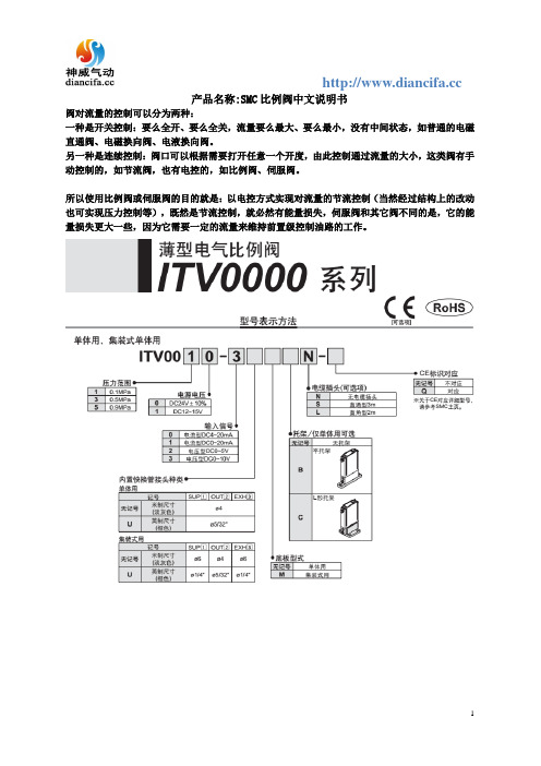
产品名称:SMC比例阀中文说明书
阀对流量的控制可以分为两种:
一种是开关控制:要么全开、要么全关,流量要么最大、要么最小,没有中间状态,如普通的电磁直通阀、电磁换向阀、电液换向阀。
另一种是连续控制:阀口可以根据需要打开任意一个开度,由此控制通过流量的大小,这类阀有手动控制的,如节流阀,也有电控的,如比例阀、伺服阀。
所以使用比例阀或伺服阀的目的就是:以电控方式实现对流量的节流控制(当然经过结构上的改动也可实现压力控制等),既然是节流控制,就必然有能量损失,伺服阀和其它阀不同的是,它的能量损失更大一些,因为它需要一定的流量来维持前置级控制油路的工作。
SMC系列产品使用说明书

5.3对于1-PC和牙嵌式驱动空心轴的电动装置其安装方法是:起吊电动装置使1-PC空心轴孔与阀杆和键配合装入,牙嵌驱式空心轴上的牙嵌与阀门上阀杆螺母的牙嵌对准。用螺栓将电动装置与阀门紧固可靠。
4.1专用电动机:适合阀门的载荷特性和使用工况,型号YLT。
4.2减速机构:用于传递和增大电动机的动力。每个机座产品均有3~5种速比的蜗轮副和若干电机齿轮与蜗杆轴齿轮传动比的齿轮副,因而可获得较大的输出转速范围。
4.3驱动空心轴:它是电动装置的动力输出部件,有2-PC、1-PC、牙嵌式三种型式,结构可见(图10)~(图12)
2.基本技术参数
产品符合JB/T8528-1997《普通型阀门电动装置技术条件》
2.1动力电源:380V、50Hz三相正弦交流电(根据用户要求,某些规格可提供使用单相220V电源的电动机)。
2.2外壳防护等级:SMC-04、03 IP67
SMC-00~5 IP65
2.3使用环境温度:-20℃~40℃;-20℃~60℃(根据用户订货要求)
G·L·SW各列转体上触点的相对位置可任意布置,即同一列上的触点可以全部为“OFF”型式或为“OFF”“ON”两种型式。(最常用的是“OFF”“ON”的布置型式)。
G·L·SW中间的两列转体触点开关可做为阀门某两个中间位置的信号输出,也可将其调整到与两边的转体同步动作。
(图17)为典型控制原理时触点开关的布置型式。
电气接线程序及注意事项:
7.1确认电源电压与电动机使用电压相同。
SMC IS10-SMW02EN 普通开关型压力开关说明书
IS10-SMW02ENPage 1 of 1Instruction ManualNormally Open Pressure Switch IS10 SeriesThe intended use of the Pressure Switch is to detect pressure above or below a set value. The user is able to set the value in the specified range.1 Safety InstructionsThese safety instructions are intended to prevent hazardous situations and/or equipment damage. These instructions indicate the level of potential hazard with the labels of “Caution,” “Warning” or “Danger.”They are all important notes for safety and must be followed in addition to International Standards (ISO/IEC) *1), and other safety regulations. *1)ISO 4414: Pneumatic fluid power - General rules relating to systems. ISO 4413: Hydraulic fluid power - General rules relating to systems.IEC 60204-1: Safety of machinery - Electrical equipment of machines. (Part 1: General requirements)ISO 10218-1: Manipulating industrial robots -Safety. etc.∙ Refer to product catalogue, Operation Manual and Handling Precautions for SMC Products for additional information.not avoided, will result in death or serious injury.Warning∙ Always ensure compliance with relevant safety laws and standards.∙ All work must be carried out in a safe manner by a qualified person in compliance with applicable national regulations∙ System reaction time is to be determined by the machine builder2 Specificationsthe valve occurred (pulse shape: sine wave). Pulse time 11 ms.2 Specifications - continuedNOTE 2) No malfunction occurred in a sweep cycle test between 10 to 150 Hz at vibration sweep 0.35mm. The test was performed in the three axes and two directions, 7 min per cycle (20 cycles). For further test details contact SMC.3 Installation3.1 InstallationWarning∙ Do not install the product unless the safety instructions have been read and understood.∙ When handling the product, hold the body and do not apply tensile stress to the power supply cable. Otherwise, damage may occur to the product.∙ Avoid repeatedly bending or stretching the lead wire.Wiring which applies repeated bending and tensile stress to the lead wire can break the circuit. If the lead wire is damaged, causing operation failure, replace the product with a new one.∙ Do not drop or subject the product to impacts when handling.∙ Connect load before connecting with power source. The switch is instantaneously damaged when the load is not connected.∙ Make the wiring length as short as possible. When the load which is operated by the pressure switch is an inductive load, or the lead wire is 5 m or longer, use the contact protection box NOTE1 shown in the table below. Otherwise, damage to the switch can result. NOTE 1: In case of use in safety related application do not use the contact protection box CD-P11 or CD-P12• Internal circuit of contact protection box• How to connect contact protection boxConnect the lead wires from the body and the contact protective box side indicated “SWITCH.” Make the lead wire as short as possible, within 1 m.∙ Check the wiring for possible short circuits. If some of the wires are short circuited, the switch may be damaged due to excessive current flow.∙ Dimensions of lead wire Enclosure: ø 3.4 Insulator: ø 1.1 Conductor: ø 0.643.2 EnvironmentWarning∙ Do not use in an environment where corrosive gases, chemicals, salt water or steam are present.∙ Do not use in an explosive atmosphere.∙ Do not expose to direct sunlight. Use a suitable protective cover.3 Installation - continued∙ Do not install in a location subject to vibration or impact in excess of the specification. Excessive vibration may cause malfunction or may incorrect setting.∙ Do not mount in a location exposed to radiant heat.∙ Do not apply vacuum. If this occurs this may result in breakage.∙ Applicable fluid is limited to air and inert gas. Other fluids are not acceptable. Especially, never use flammable fluid and gas, which may result in explosion since the product is not designed to be explosion-proof.∙ Avoid using the switch in a magnetic environment. It may cause a malfunction.∙ Do not use in such an environment, where water or oil is splashed. Since it is the open type construction, if water or oil enters into the internal parts, the electric circuit will be corroded and may result in a malfunction or damage.∙ Supply the pressure for the product continuously to operate a switch. If the increasing or decreasing pressure is slow, there will be “stick -slip”. 3.3 PipingCaution∙ Before piping make sure to clean up chips, cutting oil, dust etc.∙ When installing piping or fittings, ensure sealant material does not enter inside the port. When using seal tape, leave 1 thread exposed on the end of the pipe/fitting.∙ Tighten fittings to the specified tightening torque. Recommended tightening torque:∙ Apply a wrench to the bottom of the product when screwing.Turning it by applying a wrench on the top of the main body may cause damage to the product. Recommended tightening torque: 7 to 9 N·m∙ To screw piping materials into components, tighten with a recommended tightening torque while holding the female thread side. If the minimum tightening torque is not observed, this can cause clearance in the connection between male and female fittings leading to seal leakage.∙ Excess tightening torque can cause damage to the threads. Furthermore, tightening without holding the female thread side can cause damage due to the excess force that is applied directly to the bracket.∙ Mounting direction is available in either horizontal or perpendicular. ∙ This product (IS10 series) uses a reed switch. If the chattering of the output signal is a problem, choose a solid state type pressure switch or adjust by PLC.3.4 LubricationCaution∙ SMC products have been lubricated for life at manufacture, and do not require lubrication in service.∙ If a lubricant is used in the system, refer to catalogue for details.4 Settings∙ Please set the product within the range of the display pressure in the scale plate.∙ There is a possibility that defective operation and a set gap are generated when outside of the range of the display pressure and setting pressure.∙ Turn the adjusting screw and place the red line of adjustment screw in line with the marking on the scale plate. Turn clockwise to adjust for high pressure.∙ Use a screwdriver of a size suitable for the head of adjustment screw. ∙ The scale displays the value for the off pressure.∙ When detecting the ON-pressure signal, note that set pressure on scale plate plus ON-OFF differential (Hysteresis) will be ON-pressure signal.∙ Pressure display on the scale plate is just as a reference guide. For an accurate setting, measure it by pressure gauge.5 How to Order∙ Please refer to the catalogue.6 Outline Dimensions (mm)∙ Please refer to the catalogue.7 Maintenance7.1 General MaintenanceCaution∙ Not following proper maintenance procedures could cause the product to malfunction and lead to equipment damage. ∙ If handled improperly, compressed air can be dangerous.Maintenance of pneumatic systems should be performed only by qualified personnel.∙ Before performing maintenance, turn off the power supply and be sure to cut off the supply pressure. Confirm that the air is released to atmosphere.∙ After installation and maintenance, apply operating pressure and power to the equipment and perform appropriate functional and leakage tests to make sure the equipment is installed correctly.∙ If any electrical connections are disturbed during maintenance, ensure they are reconnected correctly and safety checks are carried out as required to ensure continued compliance with applicable national regulations.∙ Do not make any modification to the product.∙ Do not disassemble the product, unless required by installation or maintenance instructions.∙ Perform periodic inspections to ensure proper operation of the switch. Verifying the operation of the switch on a regular basis can minimize unexpected problems with a machine or equipment.∙ Wear safety glasses when conducting periodic inspections.∙ Take precautions when using a switch for an interlock circuit. When a pressure switch is used for an interlock circuit, devise a multiple interlock system to prevent trouble or malfunction. Verify the operation of the switch and interlock function on a regular basis.∙ Ensure there is enough space around the product to carry out maintenance.8 Limitations of Use8.1 Limited warranty and Disclaimer/Compliance Requirements Refer to Handling Precautions for SMC Products.9 ContactsRefer to Declaration of Conformity and for contacts.URL : http// (Global) http// (Europe) 'SMC Corporation, Akihabara UDX15F, 4-14-1, Sotokanda, Chiyoda-ku, Tokyo 101 0021Specifications are subject to change without prior notice from the manufacturer. © 2018 SMC Corporation All Rights Reserved. Template DKP50047-F-085HORIGINAL INSTRUCTIONSRefer to Declaration of Conformity for relevant Directives。
SMC PF2A3 PF2W3 PF2D3 流量监测仪操作手册说明书
Flow MonitorOperation ManualPF2A3/PF2W3/PF2D3Installation•Never mount the product in a location that will be used as a foothold.Thank you for purchasing an SMC PF2A3/PF2W3/PF2D3Series Flow Monitor.Please read this manual carefully before operating the product and make sure you understand its capabilities and limitations.Please keep this manual handy for future reference.To obtain more detailed information about operating this product, please refer to the SMC website (URL ) or contact SMC directly.These safety instructions are intended to prevent hazardous situations and/or equipment damage.These instructions indicate the level of potential hazard with the labels of"Caution", "Warning" or "Danger". They are all important notes for safety and must be followed in addition to International standards (ISO/IEC) and other safety regulations.OperatorSafety InstructionsMaintenanceHow to reset the product after a power cut or forcible de-energizing The setting of the product will be retained as it was before a power cut or de-energizing.The output condition is also basically recovered to that before a power cut or de-energizing, but may change depending on the operating environment.Therefore, check the safety of the whole installation before operating the product.Mounting and InstallationInstallingRemoving the panel mount adapter•Remove the panel mount adapter from the product if it has been delivered assembled.•Remove the mounting bracket using a flat blade screwdriver.•Lever the hook to the outside to remove the adapter (See below).•If the panel mount adapter is pulled with the hook engaged, the product or the panel mount adapter will be damaged.FrontBackList of outputsFind the diagram of the output required in the table below. Perform settings following the Set value column on the right. Characters in ( ) are for OUT2.Key-lock functionThis function is used to prevent errors occurring due to unintentional changes of the set values.Default settingsThe default settings are as follows.If this condition is acceptable, then keep these settings.Default settingsThe default settings are as follows.If this condition is acceptable, then keep these settings.∗: When Non-Reverse output is selected as the switching operation, n becomes P.button, to display [F_].This [F_∗: When OUT1 or OUT2 is assigned to be instantaneous output mode during initialize mode, [F_1] and [F_2] are displayed.When OUT1 or OUT2 is assigned to be accumulated output mode, [F_3] is displayed.Items below can be set.•Connected sensor •Display mode •Unit selection function ∗•Output mode (OUT1)•Output mode (OUT2) •Switch operation (OUT1)•Switch operation (OUT2)•Reference condition TroubleshootingMounting with the panel mount adapter •Install the product as shown below.•Insert panel mount adapter B into section A of panel mount adapter A.Push panel mount adapter B from behind until the display is fixed onto the panel.The pin of panel mount adapter B engages the notched part of panel adapter section A to fix the display.Wiring•Connections should only be made with the power supply turned off.•Use separate routes for the product wiring and any power or high voltage wiring. Otherwise, malfunction may result due to noise.•Ensure that the FG terminal is connected to ground when using a commercially available switch-mode power supply. When a switch-mode power supply is connected to the product, switching noise will be superimposed and theproduct specification can no longer be met. This can be prevented by inserting a noise filter, such as a line noise filter and ferrite core, between the switch-mode power supply and the product, or by using a series power supply instead of a switch-mode power supply.Connecting the wiring•Use suitable crimp terminals for connection to the terminal block.•Attention should be paid to the terminals to avoid short circuits.Terminal block numberPower is suppliedOutline of settingMeasurement modeThe mode in which the flow is detected and displayed,and the switch function is operating.This is the basic operating mode;and other modes should be selected for settingchanges and other function settings.Function selection modeSpecification / Outline with DimensionsRefer to the product catalogue or SMC website (URL ) for more information about product specifications and outline dimensions in detail.Note: Specifications are subject to change without prior notice and any obligation on the part of the manufacturer.© 2011 SMC Corporation All Rights ReservedAkihabara UDX 15F , 4-14-1, Sotokanda, Chiyoda-ku, Tokyo 101-0021, JAP AN Phone: +81 3-5207-8249 Fax: +81 3-5298-5362URL Refer to the SMC website (URL ) for more information about troubleshooting.∗1: In window comparator mode, the hysteresis is fixed at 3 digits. When setting, allow 7 digits or more betweenSet point 1 and Set point 2 (Set point 3 and Set point 4).∗2: When Set point 1 = Set point 2 (Set point 3 = Set point 4), chattering may occur.Refer to the product catalogue or SMC website (URL )for more detailed information about panel cut-out dimensions.。
SMC操作手册

泵浦馬達專用緩衝器 (SP精巧型系列) 使用及操作維護手冊
謝謝你的購買 使用之前請詳細閱讀,並請妥善保存「說明書」及「保證書」 Chinese Edition v01.10.2 June.11.2012 Made.
Soft Start Pump Motor Controller of SP series. 泵浦緩衝器索引 I. 面板功能與說明……………………………….P.1 II. 功能簡介……………………………………….P.4 III. 技術規格……………………………………….P.5 IV. 型號規格選擇………………………………….P.6 V. 安裝注意事項………………………………….P.7 VI. 應用與設定…………………………………….P.9 VII. 各項功能設定…………………………………P.10 VIII. 過載電流設定說明……………………………P.11 IX. 出廠標準過載電流設定表……………………P.12 X. 控制接點功能註解……………………………P.13 XI. 一般建議控制圖………………………………P.14 XII. SMC與直接啟動、Y-△啟動電流比較圖…..P.15 XIII. 環境特性………………………………………P.16 XIV. 產品保證書……………………………………P.17 I. 面板功能與說明 1. 輔助電源指示燈。 9. SW1:各項功能選擇。 2. 啟動中、運轉中、緩停中指示燈。 10. SW2:過載電流設定。 3. 啟動完成指示燈。 4. 異常指示燈(Error)。 5. 啟動扭力(100%~500%)。 6. 啟動時間(1S.~40S.)。 7. 停止時間(1S.~60S.) 8. 復歸鍵
P.1 1-1. 面板LED燈號說明: 1.Power: (AC1, AC2)輔助電源接上時指示燈會亮起,220VAC
50/60Hz(自動判斷)。 2. Running:啟動中、運轉中、緩停中指示燈會亮起。 3. Run:啟動完成指示燈亮起。 4. Error:包括過載、欠相、卡死、本體過溫保護、低載指示燈。
- 1、下载文档前请自行甄别文档内容的完整性,平台不提供额外的编辑、内容补充、找答案等附加服务。
- 2、"仅部分预览"的文档,不可在线预览部分如存在完整性等问题,可反馈申请退款(可完整预览的文档不适用该条件!)。
- 3、如文档侵犯您的权益,请联系客服反馈,我们会尽快为您处理(人工客服工作时间:9:00-18:30)。
④在如下条件及环境下使用时,请考虑安全对策,同时与本公司联络。 1. 在明确记录的规格以外的条件、环境及室外使用时。 2. 与原子能、铁道、航空、车辆、医疗设施、饮料及食料接触的设备、娱乐设备、紧急切断回路、冲 压用离合器制动回路、安全设备等配套使用时。 3. 在可能对人体及财产产生重大影响、特别要求在安全的用途下使用时。
■禁止接触纯水・药液流体用以及高温流体流量开关的管路连接部及管路, 可能导致烫伤。 请确认冷却后再触摸。
■开关的管路连接后,须确认没有漏液。 如果对流体泄漏不实施处理,可能导致烫伤(纯水・药液流体及水用高温流体)及机械・装置 等损伤。
-3-
操作上的注意事项
数字式流量开关的设计・选择・使用时,请遵守以下内容。 z 关于设计・选择(请同时遵守以下与操作有关的组装・配线・使用环境・调节・使用・维护检查的内容。)
-4-
・ 请勿将流量开关设置在可能脚踏的场所。 因失误脚踏、站立可能加注过大载重量导致破损。
・ 在流体内可能混入异物时,请在1次一侧(流入侧)设置过滤器或气水分离器(空气用时)。 成为故障、错误运转的原因。另外,还无法正确测量。
・ 应使液体能够经常注满检测管路内进行设计・设置。 垂直安装时,请让液体从下方向上方流动。 如混入气体的气泡,可能导致无法正确测量。
*调节・使用 ・ 请勿让负荷短路。
流量开关的负荷短路时,将有错误显示,但是因过大电流流过可能导致流量开关的破损。 ・ 请勿使用尖状物按各个设定按钮。
②请由有充分的知识和经验的人员进行操作。 错误的使用压缩空气,会发生危险。使用空压机设备的机械、装置的组装、操作及维修等,应由具有充 分知识和经验的人员进行。
③在确认安全之前,请勿进行机械・装置的操作以及设备的拆卸。 1. 机械・装置的检查及整备,应该在确认了已采取被驱动物体掉落防止措施及失控防止措施等之后进 行。 2. 在拆卸设备时,请在确认已采取上述安全措施,已切断作为能源的空气输送及该设备的电源,并已 排出系统内的压缩空气之后进行。 3. 重新启动机械・装置时,请在确认已经采取了飞出防止措施之后进行。
■在实施组装・操作・维护检查时,请熟读本使用说明书并充分理解相关内容后方可开始作业。
■关于用途限制
■本产品是针对一般的FA机器使用而设计的。 请勿将本产品与直接与生命相关的设备・装置等*1以及因错误操作和故障将导致巨大损害的设备・ 装置等配套使用。 *1 :所谓直接与生命有关的设备・装置是指: ・ 生命维持装置及手术室用设备等医疗用设备 ・ 根据消防法规、建筑基准法规等各种法令规定必须使用的装置 ・ 符合上述规定的设备・装置
-5-
・ 请根据具体保护结构,考虑使用环境后使用。 IP20 规格的流量开关,请避免在水及油等飞溅的场所使用。
・ 请将流量开关安装在没有振动(98m/s2 以下,但是,纯水・药液用的传感器部位为 4.9m/s2 以下)、冲击的 场所。 可能导致故障、错误运转。
・ 在水用・空气用时,如在低温(5℃以下)中使用,因液体或空气中的水分冻结可能导致破损、运转不良。 请采取防止冻结措施。 在空气中用时,建议设置空气干燥设施实施排水・排除水分。 另外,即便是规定温度内,也请避免温度的急剧变化。
■图标的说明 图标
图 标 的 含义
禁止 指示
“ ”表示禁止(不允许发生的行为)。 具体的禁止内容是采用图形和文字标示于图标中或其附近。
“ ”表示强制(必须落实)执行的行为。 具体的指示内容是采用图形和文字标示于图标中或其附近。
■关于操作者
■本操作说明书是使用空气压设备的机械・装置的组装、操作、维护检查的方法,是针对对此种机器 有非常丰富的知识和经验的人员编写的。组装・操作・维护检查的实施,也仅限于此类人员。
■请勿在易燃性的液体及渗透性高的液体中使用。 有可能导致火灾及爆炸・破损・腐蚀。 *关于纯水・药液流体用流量开关,请阅览所使用的药液附带的药液 MSDS(产品安全数据 表)。 *在空气中用时,请将流速检出部加热到 150℃后使用。
■在连锁回路使用时 ・ 须通过个别系统(机械式保护机能等)设置双重连锁 ・ 须实施是否正常运转的检查作业 可能因错误操作导致事故。
文件号:PF※※-OMG0013-A
操作技术资料
产品名称:数字流量开关(一体型)
适用型号:
空气用 PF2A710/750 系列
Байду номын сангаас
PF2A711/721/751 系列
水用 PF2W704/720/740 系列
PF2W711 系列
水用(高温流体)PF2W704T/720T/740T 系列
目录
使用前 型号表示方法 规格 外形尺寸图 各部的名称和作用 安装方法 内部回路和线路举例 设定方法 初始设定 累计流量表示功能 瞬时流量设定模式 累计流量设定模式 输出方式 其它功能
■为了防止本产品因环境应力(经间变化)等原因,在一定概率下发生故障・误动作导致的危害与损伤, 请务必采取特别的安全和维护措施。 *所谓特别措施,是指在设备・装置的设计阶段进行充分的研讨,预先将设备・装置构筑为多重化设 计和失效保护设计等备份系统。
-2-
安全注意事项
注意
①关于空压机的适合性,请由空压系统的设计者或决定规格的人员进行判断。 在此揭示的产品,因使用条件的多样性,在确认该系统的适合性时,请由空压系统的设计者或决定规格 的人员根据需要进行分析及试验后决定。所希望的系统性能和安全性保证由决定系统适合性的人员负 责。今后也应根据最新的产品目录及资料,探讨规格的全部内容,并考虑有关设备可能发生故障的状况 后构建系统。
以下,(温度范围:0~90 度)。 * 如果是高温液体用,只限使用水(温度范围:0~90 度)及甘醇 50%的水溶液(须为 3MPa・s 以下)。 ・ 请在规定电压下使用。 在规定以外的电压下使用,可能导致错误运转・流量开关的破损。 在低于规定电压时,因流量开关的内部电压降低,有时发生负荷不作动的情况。 请确认负荷动作时的电压后使用。 ・ 请在规定的测试流量・使用压力下使用。 可能导致流量开关的破损・无法正常的计量。 水用的时候,请注意不要因水锤现象而另外加注规定压力以上的压力。 <减低水锤对策事例> ①:使用水锤缓和阀等,稳定关阀时速度。 ②:使用橡胶软管等弹性管路材料及储液器吸收冲击压力。 ③:尽可能缩短管路的长度。 ・ 使用时,请勿超过最大负荷容量。 可能导致流量开关破损。 ・ 输入流量开关的数据,即使切断电源也不会消失。 (换写次数:106次,数据保存时间:20 年) ・ 请通过流量特性(压力损失)图确认使用流量中传感器部位的压力损失后再设计管路。 请通过流量特性图确认传感部位的压力损失。 ・ 请确保维护空间。 进行设计时,请考虑维护检查作业所需的空间。 z 关于使用上的注意事项 *安装 ・ 请勿掉落、打击、加以过度的冲击(490m/s2)。 可能导致流量开关破损、故障・错误操作。 ・ 请勿用力拉拽导线,或拉起导线将本体拉起。(拉拽强度为 49N 以内)使用时,请将本体托起。 可能导致流量开关破损,故障・错误操作。 ・ 请严格保证紧固扭矩。 如超出紧固扭矩进行紧固,可能导致接线端子台螺钉及接线端子台的破损。 另外,如果低于紧固扭矩进行紧固,可能导致流量开关的安装位置歪斜。(请参照流量开关安装方法。) ・ 安装流量开关管路时,请在与管路部分一体的金属部分(管路配件)使用扳钳作业。 如在其它部分使用扳钳,可能导致流量开关的破损。 ・ 请配合产品(本体)上表示的液体流动方向,进行设置・配管作业。 空气的滞留可能导致无法正确测量。 ・ 空气用时,请勿将本体底部向上安装。 空气的滞留可能导致无法正确测量。 ・ 请使用吹风机将管路内残留的垃圾等排出后,再对流量开关进行配管。 可能导致故障、错误作动。
-1-
P3 P8 P9 P11 P14 P14 P16 P16 P18 P18 P18 P19 P20 P23
安全注意事项
安全注意事项
为了明确表示危害和损害的程度,分别使用“警告”和“注意”进行区分。 为了确保安全,请参照以下 ISO・JIS 以及其它安全规则。
警告: 表示错误操作时可能导致人员死亡和重伤的事项。 注意: 表示错误操作时可能导致人员受伤或发生物质损坏的事项。
・ 流量开关前后的管路,请设置为管路半径的8倍以上的直管。 另外,因具体管路配置条件不同,可能发生气泡,请参考推荐的配管案例。 管路内的压力及液体分布的变化,或气泡的滞留可能导致无法正确测量。
*线路 ・ 请勿重复的弯折及拉伸导线。
如果导线的配置可能导致重复用力弯折及拉伸,将引起断线。 另外,弯曲的半径原则上在 R65mm 以上。 ・ 请勿错误接线。 错误接线的不同情况,可能破坏流量开关。 ・ 请勿在接通电源时进行接线作业。 可能导致单元内部发生破损或错误运转。 ・ 请勿与动力线及高压线使用相同的接线线路。 因动力线・高压线输出的信号线中的噪音・电涌的混入可能导致发生错误的运转。 流量开关的接线线路请与动力线・高压线分开(不同线路)配置。 ・ 请确认线路的绝缘性。 如果绝缘不良(与其它线路混触,接线末端间的不良 etc),由于向流量开关附加过大电压负荷或混入电 流,可能会导致流量开关破坏。 ・ 为了防止混入噪音・电涌,请尽量缩短线路。 请将长度维持在 100m 以下。 *使用环境 ・ 请勿在腐蚀性气体及液体中使用。 可能导致故障、错误运转。 ・ 请勿在水・药液・油飞溅的场所使用。 可能导致故障、错误运转。 ・ 请勿在发生磁场的场所使用。 可能导致流量开关的错误运转。 ・ 请勿在经常会被水飞溅的环境下使用流量开关。 请避免在经常会被水飞溅的环境下使用流量开关。 绝缘不良、流量开关内部密封树脂的膨胀可能导致错误运转。 ・ 请勿在油分・药品环境中使用。 对于在切削液及清洗液等、各种油类及药品的环境下使用时,有时短期内也有可能对流量开关产生恶 性影响(绝缘不良、流量开关树脂的膨胀所导致的错误运装、导线硬化等)。 ・ 请勿在温度不稳定的环境下使用。 在正常气温变化以外的温度变化环境中使用,可能对流量开关内部造成恶性影响。 ・ 请勿在电涌发生源的场所内使用。 在流量开关周围,如发生大量电涌的装置设备(电磁式升降机·高频诱导炉·电动机等)放置时,可能导致 流量开关内部回路元件的老化或者破损。因此,请考虑电涌发生源的对策,同时注意避免管路的混触。 ・ 请勿使用发生电涌的负荷。 在继电器・电磁阀等直接驱动可发生电涌电压的负荷上,请使用内藏型电涌吸收元件的产品。 ・ 因在 CE 标注中未含对雷电涌的耐性,所以请在装置方面制定雷电涌对策。 ・ 请勿让线路杂物等异物混入产品内部。 可能导致故障、错误运转,所以请勿让线路杂物等异物混入流量开关内部。