KO8G变式维护操作手册
操作手册(维护系统)4.0

u商业管理系统—维护系统操作手册前言一、系统管理1人员权限1) 操作组管理1、截图2、说明操作组主要反应具备类似业务管理职能的一组操作员,注意是类似而不是相同,同一组的操作员都会使用相同的功能模块,但可能管理不同课的业务,或在不同的机构; 操作组权限可设置到模块的每一个操作权限,它主要反应了企业中不同类型岗位的定义及其职责。
3、操作注意事项A、只能在总部设置B、因不同类型的系统(应用)对应不一样的功能模块体系,故操作组必须按不同的系统类型分别定义模块权限、操作权限、功能权限。
C、注意是岗位类型而不是具体的岗位D、新加的模块需要在这里添加权限。
E、组权限可继承修改2) 收银组管理1、截图2、说明收银组主要反映具备相同收银操作职能的一组收银员,收银组贯穿所有门店,与具体应用无关。
3、操作注意事项A、收银组权限包括前台收银机操作键位的权限设置B、只能在总部设置3) 操作员管理1、截图2、说明操作员反映每种操作组中每个具体的岗位,其对应的机构权限指操作员能在那些机构对应的软件系统中登录,课别权限反映其进入系统后能看到的数据;在同类应用中,操作员只能对应一个操作组,但允许操作员在不同的应用中对应多个组;关于操作员领导设定则有特殊的意义与作用(即品类级别和管辖人员),它可以使某一操作员的上级领导在需要时接管该操作员的全部任务,即以该操作员相同的权限进行其全部权限业务处理。
可有效用于管理监督及应急处理,如某课主管不在岗,其部门领导可接管处理及审批相关单据。
(如果需要进入多个机构进行操作可在设置操作员所属机构时选“全局用户”,即相同的用户口令可以在任何门店系统登陆作业)全局用户:指该操作员可以登录所有机构,非全局操作员只能登录指定的那个机构。
操作员品类级别的全局,并不是指操作员可以在各系统使用,而是指操作员的品类级别不分课和处,但是品类级别为全局的操作员,不能成为默认的任务接收人。
除非此步权限没有其它默认接收人,并且没有其他人有权限,则他才能成为默认接收人。
噢易维护系统-变量版使用手册(印刷版)

聲明歡迎使用噢易科技產品,在使用產品之前,請首先閱讀本使用手冊。
本手冊適用于噢易維護系統-變量版和噢易保護卡版本。
本手冊由武漢噢易科技有限公司製作。
未經噢易科技許可,不得以任何目的而使用任何形式的複製或傳播本手冊的任何部分。
武漢噢易科技有限公司有權更改本手冊的內容,如手冊內容與實際產品不符,以實際產品為准,恕不另行通知!武漢噢易科技有限公司對於產品、應用程式、版權和其中涵蓋的其他知識產權擁有專利,若無噢易科技的書面授權,不得擅用。
本手冊中所提到的某些產品名稱僅作識別之用,這些名稱可能屬於其他公司的注冊商標或版權!目錄使用手冊閱讀導航 (4)第一章產品介紹 (5)1、產品說明 (5)2、產品規格 (5)3、產品特色 (6)4、系統需求 (7)5、硬體安裝 (7)6、安裝流程圖 (8)第二章在單機或網路中的第一部電腦上進行安裝 (9)1、在本機已經安裝作業系統情況下的安裝步驟 (11)2、在本機無作業系統或需要安裝多作業系統時的安裝 (11)3、在作業系統中安裝驅動程式 (16)4、系統的優化 (19)第三章網路安裝與網路複製 (20)1、進入網路複製 (20)2、進入接收端 (21)3、設置佔位機 (21)4、分組 (22)5、發送資料、命令和修改IP (23)6、中斷點續傳(不適用于噢易保護卡) (28)第四章設置 (30)1、密碼設定 (30)2、參數設定 (31)3、分區信息 (34)4、網路複製 (35)5、重新分區 (35)6、版本升級 (35)7、移除 (36)8、關於 (37)9.計費擴展 (38)第五章變量複製(不適用于噢易保護卡) (40)1、首先根據需要在一部機器上進行操作 (40)2、進入發射端 (41)3、部分變量和全部變量 (41)4、變量複製 (42)附錄一、LINUX安裝指南 (43)附錄二、常見問題解答 (47)使用手冊閱讀導航歡迎使用噢易科技產品,在使用產品之前,請首先閱讀本使用手冊。
sap内部订单会计

1. 内部订单会计功能概述:企业在生产经营过程中,会在一段时间内发生一些专项任务或活动。
这些任务持续时间可能跨若干个会计期间,受益对象或参与部门也可能跨多个成本中心。
在任务或活动的存续期间,我们需要用到内部订单来归集它们所发生的费用。
在每个会计期末或任务结束后,通过设定一定的结算规则,将这些费用分配、分摊到相关的一个或多个成本中心中。
1.1 主数据维护1.1.1 创建内部订单描述创建内部订单主数据菜单路径管理会计->内部订单会计->主数据维护->创建内部订单事务代码KO01-创建内部订单双击菜单或在“命令框”中输入事务代码,回车进入“创建内部订单:初始屏幕”,屏幕如下:在“订单类型”字段中输入(或点击选择)所要创建的内部订单类型。
如果需要从某个订单复制,在“参照”菜单中输入源订单的订单号。
然后点击(或点击;或敲击回车)准备进入“创建内部订单:主数据”画面。
注意:如果是本次登录后首次创建内部订单,在进入“创建内部订单:主数据”画面前,系统还会弹出“设置成本控制范围”的对话框,屏幕如下:在“控制范围”字段中输入(或点击选择)“CLIC”,然后点击;或敲击回车,进入“创建内部订单:主数据”画面。
屏幕如下:首行的“订单”字段是指此次创建内部订单的订单号。
此序号是在点击保存时由系统自动赋号,这里不用输入。
第二行的“描述”字段,输入对所要创建的内部订单的相关属性的文字描述。
如“浙江省分公司培训中心大楼项目”。
中国人寿新一代财务与人力资源管理系统-最终用户操作手册在标签中,逐条输入创建内部订单所需的字段。
这里用户可根据字段输入框的状态,来判别字段的输入类型。
表示该字段为必输字段;(框体蓝色)表示该字段为显示状态,不可输入或更改;(框体白色)表示该字段为可选的输入字段。
标签中的必输字段完成以后,用户可以直接点击,系统提示创建成功,并为该内部订单分配一个订单号。
用户也可以在保存前,继续维护内部订单的结算规则。
kodak冲版机触摸屏操作说明(用户版)

(图1)冲版机开机后,会出现如上屏幕(图1)表示要求按下显示屏绿色启动按钮(图2)图像的上排表示:冲版机G-86 软件版本3.05 右上角表示日期,左上角为时间。
图像中部从左到右分别表示:显影25.0度;显影速度25秒;显影毛刷转速100转/分钟;显影补充量100毫升/平方米;电导率0.0mS;水洗毛刷转速100转/分钟;烘干温度31.2度。
图像下部表示:PROGRAM:程序:1 ,2 ,3 ---其中,深色背景表示现用程序,本例为程序 “1”;已冲洗的版材数:0RUN: 机器运行功能键,按下此键,则可转换至运行状态,同时显示转换成STOP , 其表示此时再按下该键,则可停止机器运转。
参见下图(3)SLEEP:睡眠功能键,按下此键,则机器进入睡眠状态。
MENU:菜单功能键,按下此键,则进入菜单设置状态。
OFF LINE:表示机器不在工作状态。
(注:该图形无框线,不是键,仅为工作状态提示性显示。
下同) 注:目前软件版本已升级为3.09在上图(2)页面中,按下RUN 键即可显示此界面:(图3)最下一行:STOP:和ONLINE同时显示表示机器己进入运行状态,按下此键可停止机器运转, 进入OFFLINE 状态,但在冲版过程中按此键无效。
ONLINE:表示机器己进入运行状态。
READY:表示机器已准备好,可以冲版。
其主要决定于显影温度是否到达预定值范围、大盖是否盖好、液位是否正常等各种工作状态。
NO READY:即表示机器不能正常冲版,有某些工作状态不符合要求。
在图2界面中,按下1 键,则可得下述图片 ( 注:数秒钟后自动恢复至图3页面),表示在程序(l)中设置的内容及参数。
按下2 或3 ,同样可得到程序(2)或程序(3)中的设置内容。
(图4)图(4)表示程序(1)中设置的参数。
程序(1)Dev Temperature :25.0 ℃显影温度25.0度Dry Temperature :50.0 ℃ 烘干温度50.0度Dip Time :25 sec 显影时间25秒Area Replenish :100ml/㎡面积补充100毫升/每平米Time Replenish :100ml 定时补充量100毫升Time Period :60 min 定时补充周期60分钟Sleep Replenish :100ml/hr 睡眠补充100毫升/每小时Off-Time Replenish : 100ml/hr 关机补充100毫升/每小时Dev-Brush Speed :100rpm 显影毛刷速度100转/分钟Wash-Brush Speed : 100rpm 水洗毛刷速度100转/分钟Gum Apply:YES 上胶有Gum-Start Advance :0 cm 预先上胶0厘米(指印版离上胶轴的距离)Gum Duration :0 sec 上胶持续时间0秒,(指补胶泵工作时间)以上参数均可在一定范围内修改、设置,但不在此页。
黑白斯特气力杠式机台维护、使用和安装指南说明书
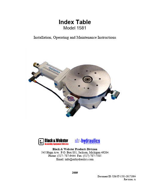
Document ID: UM-IT-1581-20171004Index TableModel 1581Installation, Operating and Maintenance InstructionsBlack & Webster Products Division545 Hupp Ave. P.O. Box 831, Jackson, Michigan 49204Phone: (517- 787-9444 Fax: (517) 787-7585Email:**********************2009Table of Contents Warranty (3)Table Hook-Up (3)Sequence of Operation (3)Table Adjustments (4)Maintenance (5)Tool Mounting Instructions (5)Parts List........................................................................................................6-8 Dimensions......................................................................................................9-10 Piping Schematic.. (11)Table Motion Lay out (12)Document ID: UM-IT-1581-20171004Revision: AWarrantyAir-Hydraulics, Inc. warrants to the original user that all products manufactured will be free from defects in material and workmanship and will possess the characteristics represented in writing. Claim for breach of the above warranty must be made within a period of one year from date of delivery to the user. Upon satisfactory proof of claim, we will make any necessary repairs or corrections, or at our discretion, replace defective parts at the factory, transportation charges prepaid. Charges for correcting defects will not be allowed, nor can we accept goods returned for correction unless we are notified in writing and the return or correction is authorized by Air-Hydraulics, Inc. in writing. The foregoing is in lieu of all other warranties, expressed or implied, including any warranties that extend beyond the description of the product. This paragraph sets forth the extent of our liability for breach of any warranty in connection with the sale or use of our products. It is understood we will not be liable for consequential damages such as loss of profit, or expense, whether based on tort or contract. This warranty is void if the articles covered by the warranty have not been properly installed, maintained and used.Table Hook-UpAir-Hydraulics Inc. recommends that the air line supplying the table be at least 1/2” pipe or 1/2” ID hose. The maximum pressure is 110 p.s.i. Anything above this could be dangerous to the machine operator and/or other personnel.Refer to the schematic on page when plumbing controls for table hook-up. One 1/2” NPT 2-position, 4-way valve controls the index cylinder and locking cylinder. Care should be taken not to restrict flow to the table.When checking the table to operation after hook-up, make sure the table is held securely (clamped or bolted). The table can shift or jump if left loose on bench.Sequence of Operation1.The directional control valve is shifted by the pilot or solenoid signal. This causes the lockingcylinder to retract, unlocking the table. Note: The signal to the solenoid or pilot must bemaintained until the table top has completed its movement.2.With the locking cylinder clear of the index ring, the index cylinder retracts, moving the index armwhich then turns the table top.3.After the index cylinder is fully retracted, the directional control valve is shifted back which forcesthe locking cylinder forward and locks the table into position. When the locking cylinder locksthe table into place, it pushes the index pawl out of the index ring.4.With the index pawl clear of the index ring, the index cylinder moves forward until it hits the stoprod. With the stop rod adjusted properly, the index pawl is spring actuated into the next slot on the index ring and the index cycle is complete.5.The index table is now ready for the next index cycle.Note: If using a manual operation to shift the directional control valve that controls the index cylinder, insure to hold the valve fully shifted until the table stops moving as a built-in cushion for the index cylinder slows the movement of the table just before the cylinder is fully retracted. If the valve is released too soon, the locking cylinder may not be able to engage the locking ring. If the table is not locked, the table top will return to its original position.Table AdjustmentsAir-Hydraulics, Inc. index tables are built, tested and adjusted at the factory prior to shipment. After receipt of the table, you may find minor adjustments are required to meet your operational requirements.The first adjustment should be in the general speed of the table during the index. To increase the indexing speed of the table, turn the speed control on the index cylinder counter-clockwise & clockwise to decrease. Care must be taken not to set the speed of the table so high that the cushion will not be able to slow the cylinder.The second adjustment is the cushion. Turning the cushion adjustment screw in the clockwise direction increases the amount of cushioning and counter-clockwise decreases the amount of cushioning. The cushion should be set so a visible slowing of the table top occurs just prior to stopping. Do not operate the index table with the cushion not functioning. Possible damage can occur if there is insufficient cushioning of the tabletop.The third adjustment is the override stop. This stop aligns the notch in the index ring with the locking cylinder plunger. If movement in the table is detected when the locking cylinder plunger engages into the index ring, loosen the large jam nut on the override stop-bolt. Make minor changes clockwise or counter-clockwise until the movement is eliminated and then re-tighten the jam nut.Adjustment of the stop-rod should not be necessary as it has been adjusted at the factory. In the event of the table being disassembled for repair or maintenance, it may become necessary to adjust. The stop-rod is used to adjust the point where the index pawl drops into a slot in the index ring and is ready to index the table top. If the stop-rod is inadvertently moved, use the following procedure to readjust the stop-rod. Remove connections for the power source from the index table; loosen the jam nut on the stop-rod until there is approximately 1-1/2” of threads showing. Make sure the table is in position to be locked and then apply power to the back of the locking cylinder. With the signal maintained to the locking cylinder, pressurize the back of the index cylinder and slowly turn the stop-rod in a clockwise direction until the pawl drops into a slot in the ring. If the table is locked up, the stop-rod will not be able to be turned when the pawl drops in the slot. Turn the stop-rod in a counter-clockwise direction ¼ to ½ turns and tighten the jam nut. The index cylinder stroke should be correct, allowing the pawl to drop into a slot every cycle.MaintenanceIn order to extend the life of the table and achieve maximum efficiency, it is recommended that all seals and gaskets be changed on a yearly basis. When changing seals and gaskets it is also recommend that the index pawl and pawl return spring be changed at the same time. After repeated index cycles, the effectiveness of the pawl return spring is lessened.A regular lubrication schedule is recommended to maintain accuracy and reliability in the index table. Grease fittings are supplied and should be greased (1-2 pumps) with a good quality lithium grease on a weekly basis to start. Take care not to over lubricate the table. Excess grease will accumulate inside of the table and will cause internal parts to move slower due to increased friction.It is recommended that at least one complete seal kit be stocked to repair your table. Seals and gaskets are sold in complete sets only.If any problems are encountered with your table, feel free to call Air-Hydraulics, Inc., Jackson, Michigan, and someone in our service department will be glad to assist you. If a comprehensive maintenance program suited for your application is desired, we can also help you set up a program.Instructions for Mounting Tooling to Air-Hydraulics Inc. Indexer1.Mount table to the machine where the drilling, tapping, reaming, etc. is to be done. If the sub-plate has already been installed by the factory, remove it from the index table.2.Connect the power source to the table with the proper valving according to the schematic andinstructions provided.3.Index the table to insure proper operation. The table must be in the locked position prior tomachining.4.Indicate sub-plate mounting holes from the center hole of the table spindle (.750” dia.). Locate thebolt and dowel pin holes from the drawing provided by Air-Hydraulics, Inc.Caution: Holes in the table top must not break through to the table base. A maximum depth of 7/8” is recommended. Use a bottom tap for 3/8-16 UNC tapped holes.5.Install the sub-plate on the table.6.Perform the work required to install tooling, tooling nests, clamps, etc. on the sub-plate at theposition required.7.Index the table and repeat step (#6) until all tooling holes are installed.8.After all holes are drilled, tapped, reamed, etc., install tooling.9.Remove the table from the drilling machine and position on the machine where it is to be used.With the table in the locked position, locate it in the desired location for machine operation.Attach the table to the plate of the machine.Note: Air-Hydraulics, Inc. recommends that the table and fixtures be doweled in place to insure repeatability.Model 1581 Parts Drawing/List1581 Index Table Parts ListNote: When ordering replacement parts for this table, specify Model 1581 and serial number. Air-hydraulics cannot be held responsible for parts shipped in error if the model and serial number are not supplied.Continued on next page.1581 Index Table Parts List – Continued* All O-rings and gaskets and seals are sold collectively as a kit. The part number is: T1581-CS.Model 1581 DimensionsModel 1581 Dimensions ContinuedDocument ID: UM-IT-1581-20171004。
SAP月结年结用户手册

<管理会计> 用户操作手册(财务组)V1.002012/10/31作者修订目录1月结 (3)1.1开、关物料账(物流集成) (3)1.1.1业务操作说明 (3)1.1.2操作步骤(MMPV) (3)1.1.3操作步骤(MMRV) (5)1.2开、关财务账(集团统一维护) (6)1.2.1业务操作说明 (6)1.1.2操作步骤 (7)1.3内部订单月结 (8)1.3.1业务操作说明 (8)1.3.2操作步骤(KO88单个月结) (8)1.3.3操作步骤(KO8G批量月结) (10)1.4CO生产订单月结 (12)1.4.1业务操作说明 (12)1.4.2操作步骤(KO88单个月结) (13)1.4.3操作步骤(CO88批量月结) (15)1.5计提折旧 (17)1.5.1业务操作说明 (17)1.5.2操作步骤(AFAB计提折旧) (18)1.5.3操作步骤(AFBP显示折旧日志) (21)1.6GR/IR自动清账(物流集成) (22)1.6.1业务操作说明 (22)1.6.2操作步骤 (23)1.7外币评估 (25)1.7.1业务操作说明 (25)1.7.2操作步骤(维护汇率_集团统一维护) (26)1.7.3操作步骤(外币评估) (28)1.8月结驾驶舱 (31)1.8.1业务操作说明 (31)1.8.2操作步骤 (32)2年结 (35)2.1总账余额结转 (35)2.1.1业务操作说明 (35)2.1.2操作步骤 (36)2.2应收应付余额结转 (38)2.2.1业务操作说明 (38)2.2.2操作步骤 (38)2.3打开资产新会计年度 (39)2.3.1业务操作说明 (39)2.3.2操作步骤 (40)2.4资产余额结转 (41)2.4.1业务操作说明 (41)2.4.2操作步骤 (41)1月结1.1开、关物料账(物流集成)1.1.1业务操作说明每月月底,财务需开、关物料账。
通过MMPV设置新的物料期间,将下一个物料期间打开,同时为了保证数据的准确性,系统同时关闭上一个期间。
科巴9850用户手册说明书

s...(L ........aes ....eAttach cups to bracket.Attach detector to bracket.Plug power cord into detector.Attach bracket towindshield.Bend bracket forcorrect detectionangle (if needed).Do not use theESD-9850 to bend bracket.Plug power cord i n to cigare t t e lighte r .Location Se l e c ting the pro p er location to mount the Co b r a ESD-9850 is ve r y impo r t a n t for optimum pe r fo r m a n c e.Both radar and laser tra n s m i s s i o n spass through glass but not through other object s .For this reason the Co b r a ESD-9850 lenses must notbe bloc k e d .The Laser Eye should have a view of therear window to take adva n tage of its 360˚ d e t e c t i o nca p a b i l i t y.It is best to locate your d e t e c tor as low on the fro n t windshield as po s s i b l e .Examples of metal in the windshield area that canblock or weaken incoming radar/laser signals:1.Windshield wiper blades.2.Mirrored sun screens.3.Regular tinted glass does not affect radarreception,although the darker tint at the top of the tinted windshield prevents laser light from penetrating.4.Heated windshields,currently available as an option for some Ford® (Instaclear) and GM®(Electriclear vehicles act as an impenetrablebarrier to radar signals).If in doubt,checkwith your dealer to see if this applies toyour vehicle.Windshield MountingLocation WindshieldMountingPlug power cordinto detector.Plug power cordi n to cigare t t e lighte r .Peel protectivepaper off one sideof hook and loopmaterial.Place on dash.Peel top paper off.Place detector on hook and loop pad.123456Rotate ON-OFF Volume Control to left (away from you).The unit will perform a self-test and the following message will appear:”…Testing…System Ready.”1Note For your convenience Display Dim,City/Highway,and Muting mode settings are retained in memory even when the power is unplugged.In both Tone and Voice Alert modes,the message “Testing...[beep,beep,beep]...System Ready”will be heard when the unit is turned on.Press and release Dim button once to selectnormal setting.Press and release Dim button a second time to select Dim setting.Press and release Dim button a third time toselect Dimmer setting.Press and release Dim button again to selectDark setting.1LED Displays NoteA four position Dim mode isprovided for dusk or nightdriving (please see Dim Button,page 10 for details).For more detailed operation instructions on display brightness,see page 10.For more detailed operation instructions on set highway/citymode,see page 12.Highway Mode Press and release City button again.HWY will be displayed for 2 seconds followed by h .A double beep confirms highway mode.Press and release City button.CTY will display while in City mode andremain on for 2 seconds.1NoteThe ESD-9850 will retain thechosen mode while O F F.Manual Muting Press and release Mute button to reduce volume while signal is in progress.MUTE will appear in the display.To Switch Between ModesPress and releaseMute Button when no signal is being received.111Plug power cord into detector.Plug power cord i n to cigaret t e lighte r .2RotateON-OFF Volume Control to the left (away from you).13For more detailedoperation instructions on setting muting mode,see page 13.The message “Testing…System Ready “ will be displayed,along with 3 beeps.The Compass directions will then be displayed.In Voice Alert,the message “Testing...System Ready”will be heard.Manual Muting of the Audio Use this operation to turn off the audio alarm atany time.Highway/City ModeTo select Highway Mode:Press and release Ci t y butto n .HWY will be displayed for 2 seconds followed by h.Press and release City button and CTY will be displayed for 2 seconds followed by c .A single beep confirms City mode.1Highway/City Mode To select City Mode:The Highway/City function is controlled by a2-s t ep butto n .Highway/City Mode Note Use City Mode in or near cities where there are many sources of false radarsignals such as microwaverelay towers and automatic door openers.This will filter out weak signals.NoteThe unit will announce“Highway”or”City”in Voice Mode.In Voice Alert,the message “Mute”will be heard.The message “Drive in 2 circles… Press City when done”will then be displayed.Drive your car in a circle twice and then pressCity.Your compass will be set.The display provides 8 primary directions;N,NE,E,SE,S,SW,W and NW.NoteYour compass may not givea correct reading if you areinside any enclosure,building or close to a large metal tractor trailer,truck ortrain.Your compass will work again correctly as soon as you get away fromthese locations.There is noneed to calibrate your compass again.CalibrateCompass Calibrate Compass The compass in your ESD-9850 must be calibrated before you use it to give accurate directions.Calibration allows the compass electronics to measure and store information about the magnetic fields from your vehicle.Press City button for a minimum of 2 passis displayed.NotePushing City button for more than 2 secondsproduces a single beep confirmation tone.NoteIf you decide to re-locate your ESD-9850 to a different location in your vehicle or move it to another vehicle,it is best to recalibrate thecompass.122Selecting Manual Muting Mode In Manual Mute mode the alerts will always be heard at the set volume level.Press and release Mute Button when no signal is being received.M ut e will appear on the display for 2 seconds,then disappear.1Auto Mutewill appear in display for 2 seco nds ,then disappe a r .All future alarms will be Au t o Mu t e.Muting Press and re l e a s e Mute b u t t on when no signal is being re c e i v e d .1Selecting Auto Muting Mode In Auto Mute mode the alerts will be heard at the volume set for 3 seconds,then automatically be reduced to a lower level.In Voice Alert,the message “AutoMute”will be heard.Memory SetThis product features an automatic,internal electronic memory system.It will automatically “remember”your settings when the unit isturned off or removed from the power source up to 7 days.Memory SetVoice/Tone SettingsPress and holdMUTE button for two seconds to change between Voice and Tone Alarms.In Tone Setting,Tone will be displayed and a beep will be heard.1Tone Alarm And V oice Alert In Voice Alert setting,the message “Voice Alert”will be heard.Laser will be displayed followed by a scrolling message of “UltraLyte”,“ProLaser”or “20/20”depending on signal received.Safety Alert ®Tr a f f i c W a r n i n gSystem and Strobe Alert ™Safety Alert® Traffic Warning System and Strobe Alert ™Safety Alert® Traffic Warning System and Strobe Alert™ will alert you with the following warnings:Emergency Vehicle,Road Hazard and Train.“Emergency Vehicle”will be displayed as scrolling message.“Road Hazard”will be displayed.“Train”will be displayed.Strobe Alert ™Safety Alert®”“Emergency Vehicle”will be displayed as scrolling message.In Voice Alert,the message “Be careful—Laseralert”will be announced,followed by the UltraLyte,ProLaser,or 20/20 tone.LIDARs must have a clearline of sight to target avehicle during the entiremeasurement interval.Intervening objects such assignposts,utility poles,treebranches,etc.,will preventa valid speed reading.420-080-N-001St r a i g h t 12V Power Co r d $10.00420-080-N -002Cu r led 12V Power Co r d $10.00545-139-N -001Windshield Mo u n ting Bra c k e t $7.00Item #Description Cost Ea.Qty.AmountPlease print clearlyNameAddress (No P.O .Box)City StateZipTelephone ( )Credit Card No.Exp.DateCustomer SignatureCircle One:Visa MasterCard Discover Allow 4 to 6 weeks for delivery.Offer valid in Continental U.S.only.For credit card orders fill out order formand fax to:1.773.622.2269or call 1.773.889.3087(Press 1 from the main menu)8:00 am - 8:00 pm,M-F,CST.Ma k e check or money order (no stamps)payable to:Cobra Electronics 6500 West Co r tland St .Ch i c a g o ,IL 60707At t n :Accessories Dept.M icrRadar/Laser Detector With Electronic Digital Compass *and Voice AlertO p e r ating Instru c tions for your Co b r a9 Band ESD 9850© 2000 Cobra Electronics Corp.Printed in ThailandPart No. 480-302-P-001If you think you need service call 1.773.889.3087“If your product should require factory service please call Cobra first before sending your unit in.This will ensure the fastest turn-around time on your repair.”You may be asked to send your unit to the Cobra factory.It will be necessary to furnish the following in order to have the product serviced and returned.1.For Warranty Repair include some form of proof-of-purchase,such as a mechanical reproduction or carbon or a sales receipt.If you send the original receipt it cannot be returned.2.Send the entire product.3.Enclose a description of what is happening with the unit.Include a typed or clearly print name and address of where the unit is to be returned.4.Pack unit securely to prevent damage in transit.If possible,use the original packing material.5.Ship prepaid and insured by way of a traceable carrier such as United Parcel Service (UPS) or First Class Mail to:Cobra Factory Service,Cobra Electronics Corporation,6500 W.Cortland St.,Chicago,IL 60707.6.If the unit is in war ranty,upon receipt of your unit it will either be repaired or exchanged depending on the model.Please allow approximately 3 to 4 weeks before contacting us for status.If the unit is out of war ranty a letter will automatically be sent informing you of the repair charge or replacement charge.If you have any questions,please call 1.773.889.3087 for assistance.If Y ou Think You Need Service and Strobe Alert™Use of this product is not intend-ed to,and does not,ensure that the motorist and any passenger will not be involved in a traffic accident.It is only intended to alert the motorist that an emer-gency or service vehicle equipped with a CODE 3,Strobe (Opticom*or Tomar Preemption System) or Cobra Safety Alert Transmitter is in the area as defined by the range of the product.Please call your local Fire/Police department to verify if coverage exists in your area.Motorists are expected to exercise all due caution while using this product,and to ob-serve and follow all applicable traffic laws.Operators of emergency or service vehicles are also expected to exercise all due caution while using this product,and to observe and follow all applicable traffic laws.*Opticom is a registered trademark of 3M Corporation Nothing comes close to a Co b r a ™© 2000 Cobra Electronics Corporation6500 West Cortland StreetChicago, IL 60707Thank you for purchasing the Cobra ESD-9850 Radar/Laser Detector.Properly used,this Cobra product will give you many years of reliable service.Customer Support Should you encounter any problems with the product or not understand its many features,please refer to this owner’s manual.If,after referring to the manual,you still need help,call Cobra Customer Service at 773.889.3087.1.On/Off Volume ControlMute ButtonDim ButtonAudio Alerts SpeakerHighway/City ButtonBand/Signal Strength/Compass DirectionIndicatorsLaser EyeWindshield BracketMount12V DC Power JackAudio JackThe C o b r a line of quality prod u c ts also includes:•Ci t i z ens Band Ra d i o s •Mi c r o T a l k ™Ra d i o s •Ac c e s s o r i e s •Sa f e t y A l e r t ™Traffic Wa r ning Sys t e m sNothing comes close to a Co b r a ™。
CORAL中文维护系统操作说明书

CORAL中文维护系统操作说明书一、本系统的主要特点1、将超级终端中使用PI终端控制控制功能、CTRL+组合键进行退格、删除等操作,转换为常用的按键操作,操作上容易被人接受。
2、将所有命令以菜单形式列出,不需记忆DAA命令和分支菜单的路径3、安装简单,操作方便,兼容超级终端的输入方式。
4、中文输出,即时翻译输出的内容,便于理解5、即时词典功能,对部分输入的内容有提示功能,帮助操作人员了解该项的内容和输入值的范围。
6、有脱机维护功能。
只需在编程过程中执行读取板卡及端口数据,即可在脱机状态下显示系统的框图,查询0-15机柜中各板的状态,及点击该板显示该板的端口数据。
并可查找某一端口号码的位置。
7、数据库可不断更新,以适应新的版本的要求。
(更新的数据库可到我方的网页上下载,下载替换掉原数据库即可)8、新增了常用操作。
对一些常用的操作用界面操作,简化操作步骤。
二、安装步骤本程序由以下几个文件组成点击“setup.exe”点击“next>”点击“yes”点击“Next>”输入系列号:111111点击“Next>”点击“Next>”点击“Next>”点击“Next>”点击“finish”完成中文维护系统的安装,中文维护系统安装完毕后,在桌面有“CORAL中文维护系统“图标三、操作说明本系统需注册后方能使用。
如没注册会显示如下界面:只可使用系统框图,可以通过手动的一些操作进行脱机查看,无法登录交换机和进入编程。
屏幕上显示本机设备码:可以用本设备码申请注册码。
输入正确后会激活菜单。
运行中文维护系统。
注册方式:将屏幕下面显示的机器设备码发送给厂商,可返回一个注册码,输入后即提示注册成功。
即可使用。
进入中文维护系统屏幕显示如下:上方有四个图标,分别是登录交换机、系统框图、常用操作、编程、退出系统菜单首先进入的是编程界面。
左边是编程菜单,单击相应的+可以展开菜单项,单击该菜单项进入相应的编程模块。