桥梁专业外文翻译--欧洲桥梁研究
桥梁术语英语词汇(简洁版)

桥梁工程英语专业词汇 approach span appropriate reinforcement design arch axis arch bridge arch bridge with suspended road arch crown arch hinge arch rib arch ring arch seat assembling bolt auxiliary bridge for construction auxiliary pier axial bearing capacity of piles axial compression strength of concrete back of arch Bailey bridge balance weight abutment bank bar barge basic wind speed basin beam bridge beam lowering bearing bearing member bearing stiffener, end stiffener bearing stratum bearing structure 引桥 适筋设计 拱轴线 拱桥 下承式拱桥 拱顶 拱铰 拱肋 拱圈 拱座 拼装螺栓 施工便桥 辅助墩 桩轴向承载力 混凝土轴心抗压强度 拱背 贝雷桥 衡重式桥台 边滩 驳船 基本风速 流域 梁式桥 落梁 支座 承重极件 端加劲肋 持力层 承重结极 mixing of concrete model modular ratio modulus of deformation for concrete modulus of elasticity for concrete modulus of elasticity in shear of timber moisture content of soil moment redistribution monolithic concrete slab bridge monolithic girder bridge motor vehicle loading movable bearing movable bridge movable supporting frame multi-cell box girder bridge multiple service bridge multiple-span rigid frame bridge multi-span natural erosion varying erosion natural ground navigation clearance negative skin friction negative stay neutral axis nominal load nominal value of an cation non-bearing member non-destructive test by ultrasonic method non-destructive test by γ-ray method 混凝土拌制 模型 模量比 混凝土变形模量 混凝土弹性模量 木材剪弹模量 土的含水量 弯矩重分布 整体式板桥 整体式梁桥 汽车荷载 活动支座 开启桥 蝴蝶架 单箱多室梁桥 多用桥 多跨刚架桥 多跨 自然冲刷 天然地基 通航净空 负摩擦力 负拉索 中性轴 标准荷载 作用标准值 非承重极件 超声波无损检验 γ射线法无ng template, bed block bed rock benchmark (B.M.) bend test of bars bending-up of flexural reinforcement bent cap. Capping bent-up bar bituminous deck pavement bleeding of concrete blind ditch block block for seismic protection bolt connection bond stress bored cast-in-situ pile bowstring arch bridge, tied-arch bridge box culvert box girder box girder with multiple cells bracket braking force and tractive force braking pier, abutment pier bridge and culvert bridge crane bridge crossing structure over river bridge deck bridge erecting crane bridge flutter bridge foundation 支承垫石 基岩 水准点 钢筋冷弯试验 钢筋的弯起 盖梁 弯起钢筋 沥青铺装桥面 泌水 盲沟 砌块 防震挡块 普通螺栓连接 粘结应力 钻孔灌注桩 系杆拱桥 箱形涵洞 箱梁 多室箱梁 牛腿 制动力和牵引力 制动墩 桥涵 桥式起重机 桥渡 桥面 架桥机 桥梁颤振 桥梁基础 oblique lap joint observation of debris flow observation of ground water observation of landslide offset of foundation one-direction raking pile foundation one-stage design one-way slab open caisson foundation open caisson notch open caisson sinking method open caisson with a "tailored" cutting edge open caisson with multi-dredge wells open caisson with single dredge well open cut foundation open floor, open deck open spandrel abutment open spandrel arch bridge open web girder bridge opening of bridge and culvert, span length ordinary rebar orthotropic plate analogy outlet submerged culvert overall length of bridge overall span length of bridge overflow bridge overflow pavement overturning stability of pier and abutment over-wrest 斜搭接接头 泥石流观测 地下水观测 滑坡观测 基础襟边 单向斜桩桩基 一阶段设计 单向板 沉井基础 深井凹槽 沉井下沉方法 高低刃脚沉井 多孔沉井 单孔沉井 明挖基础 明桥面 空腹式桥台 空腹拱桥 空腹梁桥 桥涵孔径 普通钢筋 比拟正交异性板法 压力式涵洞 桥梁全长 桥梁总跨径 漫水桥 过水路面 墩台倾覆稳定 超拧
桥梁外文翻译
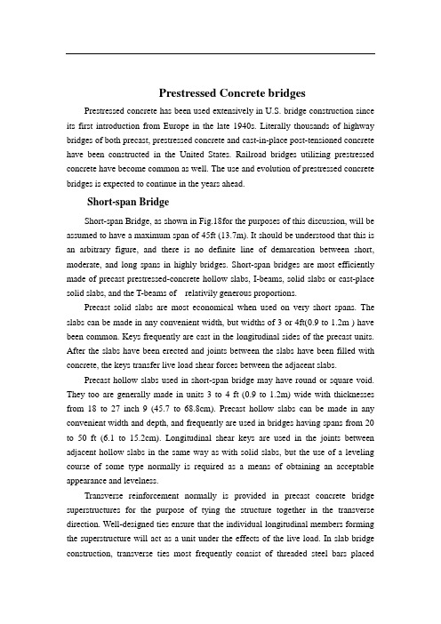
Prestressed Concrete bridgesPrestressed concrete has been used extensively in U.S. bridge construction since its first introduction from Europe in the late 1940s. Literally thousands of highway bridges of both precast, prestressed concrete and cast-in-place post-tensioned concrete have been constructed in the United States. Railroad bridges utilizing prestressed concrete have become common as well. The use and evolution of prestressed concrete bridges is expected to continue in the years ahead.Short-span BridgeShort-span Bridge, as shown in Fig.18for the purposes of this discussion, will be assumed to have a maximum span of 45ft (13.7m). It should be understood that this is an arbitrary figure, and there is no definite line of demarcation between short, moderate, and long spans in highly bridges. Short-span bridges are most efficiently made of precast prestressed-concrete hollow slabs, I-beams, solid slabs or cast-place solid slabs, and the T-beams of relativily generous proportions.Precast solid slabs are most economical when used on very short spans. The slabs can be made in any convenient width, but widths of 3 or 4ft(0.9 to 1.2m ) have been common. Keys frequently are cast in the longitudinal sides of the precast units. After the slabs have been erected and joints between the slabs have been filled with concrete, the keys transfer live load shear forces between the adjacent slabs.Precast hollow slabs used in short-span bridge may have round or square void. They too are generally made in units 3 to 4 ft (0.9 to 1.2m) wide with thicknesses from 18 to 27 inch 9 (45.7 to 68.8cm). Precast hollow slabs can be made in any convenient width and depth, and frequently are used in bridges having spans from 20 to 50 ft (6.1 to 15.2cm). Longitudinal shear keys are used in the joints between adjacent hollow slabs in the same way as with solid slabs, but the use of a leveling course of some type normally is required as a means of obtaining an acceptable appearance and levelness.Transverse reinforcement normally is provided in precast concrete bridge superstructures for the purpose of tying the structure together in the transverse direction. Well-designed ties ensure that the individual longitudinal members forming the superstructure will act as a unit under the effects of the live load. In slab bridge construction, transverse ties most frequently consist of threaded steel bars placedthrough small holes formed transversely through the member during fabrication. Nuts frequently are used as fasteners at each end of the bars. In some instances, the transverse ties consist of post tensioned tendons placed, stressed, and grouted after the slabs have been erected. The transverse tie usually extends from one side of the bridge to the other.The shear forces imposed on the stringers in short-span bridges frequently are too large to be resisted by the concrete alone. Hence, shear reinforcement normally is required. The amount of shear reinforcement required may be relatively large if the webs of the stringers are relatively thin.Concrete diaphragms, reinforced with post-tensioned reinforcement or nonprestressed reinforcement, normally are provided transversely at ends and at intermediate locations along the span in stringer-type bridges. The diaphragms ensure the lateral-distribution of the live loads to the various stringers from displacing or rotating significantly with respect to the adjacent stringers.No generalities will be made here about the relative cost of each of the above types of construction; construction costs are a function of many variables which prohibit meaningful generalizations. However, it should be noted that the stringer type of construction requires a considerably greater construction depth that is requires a considerably greater construction depth that is required for solid, hollow, or channel slab bridge superstructure. Stringer construction does not require a separate wearing surface, as do the precast slab types of construction, unless precast slabs are used to span between the stringers in lieu of the more commonly used cast-in-place reinforced concrete deck. Strings construction frequently requires smaller quantities of superstructure materials than do slab bridges (unless the spans are very short). The construction time needed to complete a bridge after the precast members have beenerected is greater with stringer framing than with the slab type of framing.Bridge of moderate spanAgain for the purposes of this discussion only, moderate spans for bridges of prestressed concrete are defined as being from 45 to 80ft (13.7 to 24.4m). Prestressed concrete bridges in this spans range generally can be divided into two types; stringer-type bridges and slab-type bridges and slab-type bridges. The majority of the precast prestressed concrete bridges constructed in the United States have been stringer bridges using I-shaped stringers, but a large number of precast prestressedconcrete bridges have been constructed with precast hollow-box girders (sometimes also called stringer). Cast-in-place post-tensioned concrete has been used extensively in the construction of hollow-box girder bridges-a form of construction that can be considered to be a slab bridge.Stringer bridges, which employ a composite, cast-in-place deck slab, have been used in virtually all parts of the United States. These stringers normally are used at spacing of about 5 to 6 ft (1.5 to 1.8m). The cast-in-place deck is generally form 6.0 to 8.0 inch (15.2 to 20.3 cm) in thickness. This type of framing is very much the same as that used on composite stringer construction for short-span bridges.Diaphragm details in moderate-span bridges are generally similar to those of the short spans, with the exception that two or three interior diaphragms sometime are used, rather than just one at mid span as in the short-span bridge.As in the case of short-span bridges, the minimum depth of construction in bridges of moderate span is obtained by using slab construction, which may be either solid-or hollow-box in cross section. Average construction depths are required when stringers with large flanges are used in composite construction, and large construction depths are required when stringers with small bottom flanges are used. Composite construction may be developed through the use of cast-in-place concrete decks or with precast construction may be developed through the use of cast-in-place concrete decks or with precast concrete decks. Lower quantities of materials normally are required with composite construction, and dead weight of the materials normally is less for stringer construction than for slab construction.Long-Span BridgesPrestressed concrete bridges having spans of the order of 100 ft are of the same general types of construction as structures having moderate span lengths, with the single exception that solid slabs are not used for long spans. The stringer spacings are frequently greater (with stringers at 7 to 9 ft) as the span lengths of bridges increase. Because of dead weight consideration, precast hollow-box construction generally is employed for spans of this length only when the depth of construction must be minimized. Cast-in-place post-tensioned hollow-box bridges with simple and continues spans frequently are used for spans on the order of 100 ft and longer.Simple, precast, prestressed stringer construction would be economical in the United States in spans up to 300 ft under some condition. However, only limited use has been made of this type of construction on spans greater than 100 ft. For very longsimple spans, the advantage of precasting frequently is nullified by the difficulties involved in handing, transporting, and erecting the girders, which may have depths as great as 10 ft and weight over 200 tons. The exceptions to this occur on large projects where all of the spans are over water of sufficient depth and character that precast beams can be handled with floating equipment, when custom girder launchers can be used, and when segmental construction techniques can be used.The use of cast-in-place, post-tensioned, box-girder bridges has been extensive. Although structures of these types occasionally are used for spans less than 100 ft, they more often are used for spans in excess of 100ft and have been used in structures having spans in excess of 300ft. Structure efficient in flexure, especially for continues bridges, the box girder is torsionally stiff and hence an excellent type of structure for use on bridges that have horizontal curvature. Some governmental agencies use this form of construction almost exclusively in urban areas where appearance from the side, is considered important.Segmental BridgesBridges that are constructed in pieces of one various connected together in some way, frequently are referred to as segmental bridges. The segments may be cast-in-place or precast, elongated units, such as portions of stringers or girders, or relatively short units that are as wide as the completed bridge superstructure.The Esbly Bridge in France is an example of one of the earliest precast concrete segmental bridges. This bridge is one of five bridges that were made with the same dimensions and utilized the same steel molds for casting the concrete units. All of the bridges span the River Marne, and because of the required navigational clearances and the low grades on the roads approaching the bridge, the depth of construction at the center of each span was restricted. The bridges were formed of precast elements, 6ft long, and were made in elaborate molds by first casting and steam-curing the top and bottom flanges in which the ends of the web reinforcement were embedded. The flanges were then jacked apart, and held apart by the web forms resulted in the prestressing of the webs. The 6-ft-long elements were temporarily post-tensioned in the factory into units approximately 40ft long. The 40ft units were transported to the bridge site, raised into place, and post-tensioned together longitudinally, after which the temporary post tensioned was removed. Each span consists of six ribs or beams that were post tensioned together transversely after they were erected. Hence, the beams are triaxially prestressed. The completed Esbly Bridge consists of a very flat,two hinged, prestressed concrete arch with a span of 243 ft and a depth at midspan of about 3ft.Cast-in-place prestressed concrete segmental construction, in which relatively short, full-width sections of a bridge superstructure are constructed, cantilevered from both sides of a pier, originated in Germany shortly after World War 2. This procedure sometimes is referred to as balanced cantilever construction. The well-known, late German engineer U.Finterwalder is credited with being originator of the technique. The basic construction sequence used in this method is illustrated in Fig.18.2 which shows that segments, erected one after another on each side of a pier, form cantilevered spans. The construction sequence normally progresses from pier to pier, from one end of the bridge to the other, with the ends of adjacent cantilevered being joined together to continuous deck. The individual segments frequently are made in lengths of 12 to 16 ft in cycles of four to seven days. The method has been used in the United States for bridges having spans as long as 750ft.The segmental construction technique also has been used with precast segments. The technique originated in France and has been used in the construction of bridges having spans in excess of 300ft. the eminent French engineer Jean Muller is credited with originating precast segment bridge construction using match cast segments. The precast segment may be erected in balanced cantilever, similar to the method described above for cast-in-place segment bridges construction in cantilever, or by using span-by-span technique. Precast segments have been made in precasting plants located on the construction site as well as off site. The segments frequently are stored for a period of weeks or months before being moved to the bridge site and erected- a factor having favorable effects on concrete strength, shrink-age, and creep. Construction of precast segmental bridge superstructures normally progresses at a rapid rate once the erection progress begins. The erection of precast concrete segments normally does not commence, however, until such time as a large number of segments have been precast and stockpiled because the erection normally can progress at a faster rate than the production of the segments.Bridge DesignThe design of bridges requires the collection of extensive date and from this the selection of possible options. From such a review the choice is narrowed down to a shortlist of potential bridge design. A sensible work plan should be devised for the marshaling and deployment of information throughout the project from conception tocompletion to completion. Such a checklist will vary from project to project but a typical example might be drawn up on the following lines.Selection of Bridge TypeThe chief factors in deciding whether a bridge will be built as girder, cantilever, truss, arch, suspension, or some other type are: (1) location ;for example, across a river ; (2) purposes; for example, a bridge for carrying motor vehicles; (3) span length;(4) strength of available materials; (5) cost ; (6) beauty and harmony with the location.Each type of bridge is most effective and economical only within a certain range of span lengths, as shown in the following table:Selection of MaterialThe bridge designer can select from a number of modern high-strength materials, including concrete, steel, and a wide variety of corrosion-resistant alloy steels.For the Verrazano-narrows bridge, for example, the designer used at least seven different kinds of alloy steel, one of which has a yield strength of 50000 pounds per square inch (psi) (3515 kgs/sq cm) and does not need to be painted because an oxide coating forms on its surface and inhibits corrosion. The designer also can select steel wires for suspension cables that have tensile strengths up to 250 000 psi (14 577 kgs/sq cm).Concrete with compressive strength as high as 8 000 psi (562.5 kgs/sq cm) can now be produced for use in bridges, and it can be given high durability against chipping and weathering by the addition of special chemical and control of the hardening process. Concrete that has been prestressed and reinforced with steel wires has a tensile strength of 250 000 psi (17 577kgs/sq cm).Other useful materials for bridges include aluminum alloys and wood. Modern structural aluminum alloys have yield strengths exceeding 40 000 psi (2 812 kgs/spcm). Laminated strips of wood glued together can be made into beams with strengths twice that of natural timbers; glue-laminated southern pine, for example, can bear working stresses approaching 3 000 psi (210.9 kgs/sq cm).Analysis of ForcesA bridge must resist a complex combination of tension, compression, bending, shear, and torsion forces. In addition, the structure must provide a safety factor as insurance against failure. The calculation of the precise nature of the individual stresses and strains in the structure, called analysis, is perhaps the most technically complex aspect of bridge building. The goal of analysis is to determine all of the forces that may act on each structural member.The forces that act on bridge structure member are produced by two kinds of loads-static and dynamic. The static load-the dead weight of bridge structure itself-is usually the greatest load. The dynamic or live load has components, including vehicles carried by the bridge, wind forces, and accumulation of ice and snow.Although the total weight of the vehicles moving over a bridge at any time is generally a small fraction of the static and dynamic load, it presents special problems to the bridge designer because of the vibration and impact stresses created by moving vehicles. For example, the sever impacts caused by irregularities of vehicle motion or bumps in the roadway may momentarily double the effect of the live load on the bridge.Wind exerts forces on a bridge both directly by striking the bridge structure and indirectly by striking vehicles that are crossing the bridge. If the wind induces aeronautic vibration, as in the case of the Tacoma Narrows Bridge, its effect may be greatly amplified. Because of this danger, the bridge designer makes provisions for the strongest winds that may occur at the bridge location. Other forces that may act on the bridge, such as stresses created by earthquake tremors must also be provided for.Special attention must often be given to the design of bridge piers, since heavy loads may be imposed on them by currents, waves, and floating ice and debris. Occasionally a pier may even be hit by a passing ship.Electronic computers are playing an everincreasing role in assisting bridge designers in the analysis of forces. The use of precise model testing particularly for studying the dynamic behavior of bridges, also helps designers. A scaled-down model of the bridge is constructed, and various gauges to measure strains, acceleration, and deforestation are placed on the model. The model bridge is then subjected to variousscaled-down loads or dynamic conditions to find out what will happen. Wind tunnel tests may also be made to ensure that nothing like the Tacoma Narrows Bridge failure can occur. With modern technological aids, there is much less chance of bridge failure than in the past.预应力混凝土桥19世纪40年代后期,预应力混凝土首次引入美国,很快便广泛应用于桥梁结构中。
道路与桥梁专业外文翻译中英对照

道路与桥梁专业外文翻译中英对照Jenny was compiled in January 2021本科毕业设计(论文)专业名称:土木工程专业(道路与桥梁)年级班级:道桥08-5班学生姓名:指导教师:二○一二年五月十八日专业外文翻译Geometric Design of HighwaysThe road is one kind of linear construction used for travel. It is made of the roadbed, the road surface, the bridge, the culvert and the tunnel. In addition, it also has the crossingof lines, the protective project and the traffic engineeringand the route facility.The roadbed is the base of road surface, road shoulder,side slope, side ditch foundations. It is stone material structure, which is designed according to route's planeposition .The roadbed, as the base of travel, must guaranteethat it has the enough intensity and the stability that can prevent the water and other natural disaster from corroding.The road surface is the surface of road. It is single or complex structure built with mixture. The road surface require being smooth, having enough intensity, good stability and anti-slippery function. The quality of road surface directly affects the safe, comfort and the traffic.Highway geometry designs to consider Highway Horizontal Alignment, Vertical Alignment two kinds of linear and cross-sectional composition of coordination, but also pay attentionto the smooth flow of the line of sight, etc. Determine theroad geometry, consider the topography, surface features,rational use of land and environmental protection factors, to make full use of the highway geometric components of reasonable size and the linear combination.DesignThe alignment of a road is shown on the plane view and is a series of straight lines called tangents connected by circular. In modern practice it is common to interpose transition orspiral curves between tangents and circular curves.Alignment must be consistent. Sudden changes from flat to sharp curves and long tangents followed by sharp curves must be avoided; otherwise, accident hazards will be created. Likewise, placing circular curves of different radii end to end (compound curves) or having a short tangent between two curves is poor practice unless suitable transitions between them are provided. Long, flat curves are preferable at all times, as they are pleasing in appearance and decrease possibility of future obsolescence. However, alignment without tangents is undesirable on two-lane roads because some drivers hesitate to pass on curves. Long, flat curves should be used for small changes in dir ection, as short curves appear as “kink”. Also horizontal and vertical alignment must be considered together, not separately. For example, a sharp horizontal curve beginning near a crest can create a serious accident hazard.A vehicle traveling in a curved path is subject to centrifugal force. This is balanced by an equal and opposite force developed through cannot exceed certain maximums, and these controls place limits on the sharpness of curves that can be used with a design speed. Usually the sharpness of a given circular curve is indicated by its radius. However, for alignment design, sharpness is commonly expressed in terms of degree of curve, which is the central angle subtended by a 100-ft length of curve. Degree of curve is inversely proportional to the radius.Tangent sections of highways carry normal cross slope; curved sections are super elevated. Provision must be made for gradual change from one to the other. This usually involves maintaining the center line of each individual roadway at profile grade while raising the outer edge and lowering theinner edge to produce the desired super elevation is attained some distance beyond the point of curve.If a vehicle travels at high speed on a carefullyrestricted path made up of tangents connected by sharp circular curve, riding is extremely uncomfortable. As the car approaches a curve, super elevation begins and the vehicle is tilted inward, but the passenger must remain vertical since there is on centrifugal force requiring compensation. When the vehicle reaches the curve, full centrifugal force develops at once, and pulls the rider outward from his vertical position. To achieve a position of equilibrium he must force his body far inward. As the remaining super elevation takes effect, further adjustment in position is required. This process is repeated in reverse order as the vehicle leaves the curve. When easement curves are introduced, the change in radius from infinity on the tangent to that of the circular curve is effected gradually so that centrifugal force also develops gradually. By careful application of super elevation along the spiral, a smooth and gradual application of centrifugal force can be had and the roughness avoided.Easement curves have been used by the railroads for many years, but their adoption by highway agencies has come only recently. This is understandable. Railroad trains must follow the precise alignment of the tracks, and the discomfort described here can be avoided only by adopting easement curves. On the other hand, the motor-vehicle operator is free to alter his lateral position on the road and can provide his own easement curves by steering into circular curves gradually. However, this weaving within a traffic lane (but sometimes into other lanes) is dangerous. Properly designed easement curves make weaving unnecessary. It is largely for safety reasons,then, that easement curves have been widely adopted by highway agencies.For the same radius circular curve, the addition ofeasement curves at the ends changes the location of the curve with relation to its tangents; hence the decision regardingtheir use should be made before the final location survey. They point of beginning of an ordinary circular curve is usually labeled the PC (point of curve) or BC (beginning of curve). Its end is marked the PT (point of tangent) or EC (end of curve).For curves that include easements, the common notation is, as stationing increases: TS (tangent to spiral), SC (spiral to circular curve), CS (circular curve to spiral), and ST (spiralgo tangent).On two-lane pavements provision of a wilder roadway is advisable on sharp curves. This will allow for such factors as(1) the tendency for drivers to shy away from the pavement edge,(2) increased effective transverse vehicle width because thefront and rear wheels do not track, and (3) added width because of the slanted position of the front of the vehicle to the roadway centerline. For 24-ft roadways, the added width is so small that it can be neglected. Only for 30mph design speedsand curves sharper than 22°does the added width reach 2 ft.For narrower pavements, however, widening assumes importance even on fairly flat curves. Recommended amounts of and procedures for curve widening are given in Geometric Design for Highways.2. GradesThe vertical alignment of the roadway and its effect on the safe and economical operation of the motor vehicle constituteone of the most important features of road design. The vertical alignment, which consists of a series of straight linesconnected by vertical parabolic or circular curves, is known as the “grade line.” When the grade line is increasing from the horizontal it is known as a “plus grade,” and when it is decreasing from the horizontal it is known as a “minusgrade.” In analyzing grade and grade controls, the designer usually studies the effect of change in grade on the centerline profile.In the establishment of a grade, an ideal situation is onein which the cut is balanced against the fill without a great deal of borrow or an excess of cut to be wasted. All haulsshould be downhill if possible and not too long. The gradeshould follow the general terrain and rise and fall in the direction of the existing drainage. In mountainous country the grade may be set to balance excavation against embankment as a clue toward least overall cost. In flat or prairie country itwill be approximately parallel to the ground surface but sufficiently above it to allow surface drainage and, where necessary, to permit the wind to clear drifting snow. Where the road approaches or follows along streams, the height of thegrade line may be dictated by the expected level of flood water. Under all conditions, smooth, flowing grade lines arepreferable to choppy ones of many short straight sections connected with short vertical curves.Changes of grade from plus to minus should be placed in cuts, and changes from a minus grade to a plus grade should be placed in fills. This will generally give a good design, and many times it will avoid the appearance of building hills and producing depressions contrary to the general existing contours of the land. Other considerations for determining the gradeline may be of more importance than the balancing of cuts and fills.Urban projects usually require a more detailed study of the controls and finer adjustment of elevations than do rural projects. It is often best to adjust the grade to meet existing conditions because of the additional expense of doing otherwise.In the analysis of grade and grade control, one of the most important considerations is the effect of grades on the operating costs of the motor vehicle. An increase in gasoline consumption and a reduction in speed are apparent when grades are increase in gasoline consumption and a reduction in speedis apparent when grades are increased. An economical approach would be to balance the added annual cost of grade reduction against the added annual cost of vehicle operation withoutgrade reduction. An accurate solution to the problem depends on the knowledge of traffic volume and type, which can be obtained only by means of a traffic survey.While maximum grades vary a great deal in various states, AASHTO recommendations make maximum grades dependent on design speed and topography. Present practice limits grades to 5 percent of a design speed of 70 mph. For a design speed of 30 mph, maximum grades typically range from 7 to 12 percent, depending on topography. Wherever long sustained grades are used, the designer should not substantially exceed the critical length of grade without the provision of climbing lanes forslow-moving vehicles. Critical grade lengths vary from 1700 ft for a 3 percent grade to 500 ft for an 8 percent grade.Long sustained grades should be less than the maximum grade on any particular section of a highway. It is often preferredto break the long sustained uniform grade by placing steeper grades at the bottom and lightening the grade near the top of the ascent. Dips in the profile grade in which vehicles may be hidden from view should also be avoided. Maximum grade forhighway is 9 percent. Standards setting minimum grades are of importance only when surface drainage is a problem as when water must be carried away in a gutter or roadside ditch. In such instances the AASHTO suggests a minimum of %.3. Sight DistanceFor safe vehicle operation, highway must be designed to give drivers a sufficient distance or clear version ahead so that they can avoid unexpected obstacles and can pass slowervehicles without danger. Sight distance is the length of highway visible ahead to the driver of a vehicle. The conceptof safe sight distance has two facets: “stopping” (or “no passing”) and “passing”.At times large objects may drop into a roadway and will do serious damage to a motor vehicle that strikes them. Again a car or truck may be forced to stop in the traffic lane in the path of following vehicles. In dither instance, proper design requires that such hazards become visible at distances great enough that drivers can stop before hitting them. Further more, it is unsafe to assume that one oncoming vehicle may avoid trouble by leaving the lane in which it is traveling, for this might result in loss of control or collision with another vehicle.Stopping sight distance is made up of two elements. Thefirst is the distance traveled after the obstruction comes into view but before the driver applies his brakes. During this period of perception and reaction, the vehicle travels at its initial velocity. The second distance is consumed while the driver brakes the vehicle to a stop. The first of these two distances is dependent on the speed of the vehicle and the perception time and brake-reaction time of the operator. The second distance depends on the speed of the vehicle; thecondition of brakes, times, and roadway surface; and the alignment and grade of the highway.On two-lane highways, opportunity to pass slow-moving vehicles must be provided at intervals. Otherwise capacity decreases and accidents increase as impatient drivers risk head-on collisions by passing when it is unsafe to do so. The minimum distance ahead that must be clear to permit safe passing is called the passing sight distance. In deciding whether or not to pass another vehicle, the driver must weigh the clear distance available to him against the distance required to carry out the sequence of events that make up the passing maneuver. Among the factors that will influence his decision are the degree of caution that he exercises and the accelerating ability of his vehicle. Because humans differ markedly, passing practices, which depend largely on human judgment and behavior rather than on the laws of mechanics, vary considerably among drivers.The geometric design is to ensure highway traffic safety foundation, the highway construction projects around the other highway on geometric design, therefore, in the geometry of the highway design process, if appear any unsafe potential factors, or low levels of combination of design, will affect the whole highway geometric design quality, and the safety of the traffic to bring adverse impact. So, on the geometry of the highway design must be focus on.公路几何设计公路是供汽车或其他车辆行驶的一种线形带状结构体。
桥梁专业英语

A2C01: Committee on General StructuresChairman: Donald J. FlemmingBridge EngineeringR AMANKUTTY K ANNANKUTTY, City of Minneapolis Department of Public WorksD ONALD J. F LEMMING, Minnesota Department of TransportationThe scope of the Transportation Research Board’s (TRBs) Committee on General Structures includes factors affecting the physical behavior, service life, economy, appearance, and safety of bridges and structures for transportation systems, and accounting for these factors and their interactions in design procedures and criteria. During the 20th century the United States has essentially created the safest, most efficient, and most effective highway and intermodal transportation network in the world. The challenge for the new millennium will be to further enhance this transportation network. In this paper the status of bridge engineering at the end of the 20th century in the area of general transportation structures is summarized. The focus is on bridge structure types, design aspects, new materials, aesthetic concerns, and key policy issues. An attempt is made to forecast the status of bridge engineering 20 to 30 years into the next millennium; the paper is written as though these forecasts will become a reality.BRIDGE STRUCTURE TYPESStructure types have been evolving throughout history. The evolution will continue into the future, perhaps at an accelerated rate.The driving forces behind continued advances in bridge engineering are traffic congestion and costs. In the future, just as now, the public will expect few traffic delays, if any. They will want transportation costs to be as low as possible. Computer technology will enhance traffic management so well that the public will become accustomed to flowing traffic and more aware of congestion locations. Disruptions from construction will be more obvious and even less tolerated. Given these conditions, structural types will be selected primarily on the basis of speed of construction to minimize traffic delays. Low maintenance will be a must, and the ability to widen a structure easily and quickly will be a priority in selecting a structure type.Safety and aesthetics will continue to play major roles in the selection of structure types. Keeping substructures out of the roadway clear zone will dictate longer span lengths and will keep the engineering community striving for optimal spans. Input from the public will grow to such a level that interactive design programs will become a necessity. Computer programs that automatically prepare detailed plans incorporating changes at the touch of a button will allow the public to modify or add aesthetic details right up to the point that construction begins.Transportation in the New Millennium2 Long SpanPosttensioning with high-strength materials will allow traditional concrete and steel bridges, especially box shapes, to reach continually longer spans that challenge steel truss bridges and even the shorter-span cable-stayed bridges. Cable-stayed bridges and suspension bridges will most likely continue to dominate the long-span bridge category. Long-span bridges will continue to be the most dramatic, capturing the public’s awareness with highly visible and innovative structures. Shown in Figure 1 are two impressive structures, the Sunshine Skyway Bridge and the Houston Ship Channel Bridge, which is the longest concrete box to date.Medium SpanMedium spans include spans from 50 to 200 feet and traditionally have been prestressed concrete girders and steel girders. In the future, new materials with high-performance characteristics will be developed, and the strengths of concrete and steel materials will be enhanced. Stronger materials and innovative design concepts will come together to yield much longer spans. The result will be simpler structures with fewer substructures and a reduction in overall cost. Space frame structures using steel and concrete in combination may enter this market because of ease of construction and relatively low cost. Preengineered, “out-of-the-box,” prefabricated component bridges will also become more common and will begin to challenge individualized designs. Innovations will cause greater change to the medium-span range than to the other two ranges. An innovative steel bridge that clear-spans an entire freeway is shown in Figure 2. Bridges that clear-span roadways will become popular in the future.Short SpanConcrete slabs, timber slabs, prestressed concrete shapes, and rolled steel shapes currently share the market for spans up to 50 feet. In the future, these types will be challenged by long-span culverts and preengineered, out-of-the-box, prefabricated component bridges. Shown in Figure 3 is a typical long-span culvert (44-foot span) that is starting to challenge more typical short-span structures.DESIGNDesigning bridges according to a standard specification became the norm in the 20th century. This will continue in the next century. However, the process of designing will be much different in the future because of changes in specifications, loads, testing, and computerization.SpecificationsThe specifications used for structural bridge design at the end of the 20th century are split between the American Association of State Highway and Transportation Officials (AASHTO) load factor design (LFD) specification and the load and resistance factor design (LRFD) specification, with LRFD recently being designated as the standard for the future. LFD will continue to be used for some time, but its usage will decline as LRFD becomes more widely accepted. Eventually LFD will be discontinued and LRFD will be fully adopted, which will prove to be the right course of action. The AASHTO LRFD specification will continue to evolve with new research, new design ideas, and newGeneral Structures3 materials. The LRFD method will prove to be effective and will be easily adapted to all construction materials including steel, concrete, timber, and the new high-strength plastic polymers.Acceptance of the LRFD method by the design community will not be easy because of concerns in two areas: substructure design and computer software. One goal in establishing the LRFD specification was to provide a more uniform level of reliability in every component of the structure, from substructure to superstructure. The design of substructures using the LRFD philosophy will remain in an immature state for several years because of a lack of accepted methods for analyzing and designing foundations. Only after more research and specification enhancement will the situation for substructures change. Widespread usage of LRFD will be somewhat slowed by the lack of computer software. The detailed nature of LRFD code requires that designers develop spreadsheets and other computer worksheets to complete computations efficiently. Introduction of programs such as the AASHTO OPIS computer program will help, but the full benefit of the new design code will not be realized for several years.LoadsAt the heart of the load specification is the design vehicle. The old HS-20 truck, which has been in use since 1944, is being questioned as a vehicle relevant to traffic needs of the 21st century. Early in the century, two specific questions will arise over the continued use of this vehicle. The first question is whether a different vehicle would better match the weigh-in-motion (WIM) data coming from the monitoring systems installed in roadways. Though the data are of questionable accuracy, they indicate definite trends—that truck lengths, weights, and traffic counts have increased dramatically since the arrival of the HS-20 truck.The second question is whether another vehicle would simplify computations. Various factors and loading conditions were applied to the HS-20 truck to make it fit the LRFD specification. In consideration of these two questions, a new “millennium truck” live-load configuration will be proposed. After extensive data collection, the testing and monitoring will begin.Field TestingTo help determine an appropriate design vehicle, a more comprehensive system of WIM sites will be installed. Because of advances in accuracy and durability of the equipment, dynamic load data will begin to agree with static load data. An accurate picture will then develop of actual truck axle loads and axle spacings on highway bridges. Emerging technologies such as quartz sensors and fiber-optic enhancements, along with piezo cable, will make more accurate data collection possible. Smart bridges will be the order of the new millennium because of a dramatic increase in the number of instrumented bridges. Actual stresses will be measured and tracked in much the same way as the National Weather Service tracks daily temperatures. The WIM information will be correlated with the information from the instrumented bridges. Analysis of the massive amounts of data will be possible through the use of high-capacity computers. The LRFD design load factors will be updated on the basis of the new data.Steel structures will especially benefit from instrumentation and field testing. In response to fatigue and associated problems, steel bridges will be instrumented to determine failure mechanisms, especially crack initiation at low stress ranges with large numbers ofTransportation in the New Millennium4 loading cycles. Emerging technologies will lead to the discovery of relationships that will bring about a refinement of design methods. Cost-effective retrofit applications for fatigue-prone details will lead to a change in bridge management planning for bridges with fatigue problems. As this knowledge increases, steel bridges will be replaced mostly for functional rather than for structural reasons.AnalysisComputer programs capable of analyzing large amounts of data will be developed. Key design parameters such as distribution factors, multiple presence factors, and uniform loads will be verified. Trends in loadings and the way structures respond to those loadings will be made easier to predict. This may lead to a simplification of design factors and equations, which will allow a drastic improvement in the speed of completing design computations. The design of bridges in the 21st century will be much easier and more accurate than at the end of the 20th century.Design ToolsMore and more states will cooperate in the use of standardized details, computer programs, and drafting details, making designs and plans more similar on a regional basis. Such standardization will tend to reduce construction costs for contractors and suppliers. Speed and accuracy will be increased.After many years of working separately, computer-aided engineering and computer-aided drafting will be successfully integrated. Designs and plans will be iterative and interactive, and plan preparation will be extremely cost-effective. Design engineers will be alerted by automatic specification checkers and code verifiers, enabling them to minimize design errors. More important, optimization of a design will be a keystroke away. Artificial intelligence will supplement institutional memories and expand designers’ options for obtaining real-time expert advice. The need to develop expert systems to check the accuracy and reliability of design software will be a challenge to bridge design professionals. Of course, associated with this challenge is the ever-present debate on professional liability. AutomationThe Internet and e-mail will be standards for communication between designers, fabricators, and contractors. It will become more common for designers and drafters in different states to combine efforts. Correspondence will be handled electronically, eliminating the time necessary to print and mail correspondence back and forth. Contractors and fabricators will view the final plans electronically.MaterialsMaterials have always played a key role in the evolution of bridge structures. Enhancements of the traditional materials of concrete, steel, and timber will continue, but the most revolutionary changes will occur in the areas of fiber-reinforced plastics (FRPs), high-strength and high-performance steel, high-performance concrete (HPC), and the blending of FRP and timber.General Structures5 FRPsToday, FRPs are in their infancy as bridge construction materials. However, further experimentation with various combinations of FRP materials will result in innovative and long-lasting solutions to simple and complex bridge construction issues. Experimental FRP bridge projects have shown that this material has inherent problems in deflection, material ductility, creep, reactivity with concrete and steel, and performance under long-term exposure to ultraviolet light and other environmental factors such as moisture, freeze-thaw, humidity, and external chemical attack. To help resolve these issues, material testing standards and design methodology will be developed to fit FRP material properties. A comprehensive research effort at the national level will be undertaken to make FRP a dependable, low-maintenance bridge material capable of delivering high performance over the life of a bridge structure.Collaboration of practicing designers, construction engineers, and bridge owners will make FRP a feasible and competitive alternative to conventional bridge construction materials. Universities will most likely expand their curricula to include FRP and other composite materials in their structural and material courses to prepare future bridge professionals to accept and fully utilize FRP.High-Strength and High-Performance SteelUnlike FRP, high-strength steel materials will be more readily accepted by bridge engineers. Initial acceptance will be gained because the new steel materials make it possible to reduce structural dead loads. Wider acceptance of high-strength steels will develop because of their enhanced material properties. Gains made in improving material toughness and weldability of high-strength steels will extend to all grades of steel. Design specifications will continue to be updated to deal with material performance issues such as welding, toughness, fabrication, and constructibility. The high-performance steel materials of today will become the standard for future construction.Advances in construction and experimentation with bridge types, such as space frames and innovative composite structures, will lead to further optimization of steel materials. FRP combined with high-strength steel has high potential for future bridge structures.High-performance reinforcing bars will become common in the new millennium. Composite bars with a steel core and a cladding of stainless steel or other noncorroding material will gain wide acceptance for use in concrete structures. Coupled with the use of HPC in bridge decks, the average life of such structures may approach twice the life span of similar structures built previously. Future national policies requiring life-cycle cost analysis will provide a large incentive to further develop and implement the use of innovative materials in bridge decks.HPCHPC is well on its way to becoming a conventional bridge construction material as a result of Strategic Highway Research Program research and Federal Highway Administration implementation efforts. The debate as to whether strength or permeability is the primary indicator of long-term durability of HPC will continue among practicing engineers. However, past case studies clearly demonstrate the need for permeability tests as an indicator of long-term concrete durability. The future is bright for HPC because it has good durability and strength characteristics, making it a versatile material. Currently, assessmentTransportation in the New Millennium6 of long-term durability is an after-the-fact determination, resulting in quality control/quality assurance problems, which hamper the use of performance-based specifications. Scientists and engineers will eventually develop a device that instantaneously predicts the long-term durability properties of hardened concrete by testing the concrete in an unhardened state.TimberNew processes of reinforcing wood will continue to be developed, including the combination of glued-laminated timber and FRP composites. The concept is similar to that of reinforced concrete; wood resists the compression load, while FRP composite resists tensile load. The concept will be commonly used in future timber structures. Advantages of this technology are in areas where bending strength controls the design (as with lower grades of wood). Reinforcing with FRP greatly increases the tensile capacity of the beams, which will allow lower grades of wood to be used economically in many structures. The new composite material will also be used where minimum clearance is a problem.Breakthroughs in the area of wood preservatives will continue. They will result in the development and refinement of new alternative treatment processes and procedures that will be environmentally sound with respect to application, use, and disposal of treated timber. Other MaterialsA significant future challenge for the construction industry will be the incorporation of recycled materials (including plastics), by-products, and waste materials into conventional and HPC construction materials. Future environmental regulations and lack of space to store waste products will bring this issue to a head. Significant time and financial resources will be spent in developing recycled materials into products suitable for use as construction materials.AESTHETIC CONCERNSPublic InvolvementPublic participation in the design process has increased in recent years because the public wants better aesthetic treatment of bridges, especially bridges considered neighborhood landmarks. Public participation will continue in the future and will likely increase. To facilitate the process, engineers will display plans using three-dimensional visualization technology. The public will be able to view and comment on the plans at hearings or on the Internet.Interactive DesignIncorporating public comment into the plans will require that last-minute changes be easily accommodated into the design and drafting process. Computer design and drafting programs that automatically adjust the designs and generate plans will allow for quick modifications. The latest engineering analytical skills will be needed to accommodate this technology. The emphasis on flexible design will undoubtedly require engineers to increase their aesthetic design skills and overall people skills.General Structures7 Aesthetic ProcessAesthetic treatment of structures will become so common that only the most remote sites will be unaffected. Nearly all bridges will have a detailed aesthetic treatment, or at least an aesthetic review. Extra planning time and design time will become an accepted part of the cost of a structure. The level of public attention will determine the extent of the aesthetic design process and the resources devoted to aesthetic considerations. Three levels of bridge aesthetic consideration and processes will tend to emerge: the highest level for landmark bridges with major cultural or aesthetic significance, a middle level for transportation corridors and urban structures, and a lower level for replacement bridges in rural and industrial settings.POLICY ISSUESSeveral issues of a political nature will need to be addressed by the engineering community during the next decade. They need to be studied and discussed so that a consensus among engineers is reached. Only in this way can the voice of our profession be heard by the public, who will ultimately decide policy.Design-BuildThe design-build method for project delivery will increase. Design-build specifications will become a major factor in acceptance and overall performance of the design-build method. The specifications need to require the contractor to consider both the life-cycle costs and the initial construction costs in the selection of materials and structure type. When the engineering community and the legal community work together to accomplish this, the bridge owners will become more comfortable with the design-build method and will begin to use it even more frequently. Successful design-build projects with improved speed of construction and reduced construction problems will continue to make this project delivery option attractive to owners.Life-Cycle CostsDuring the 20th century, computation of accurate life-cycle costs was difficult because of a limited amount of historical data. But in the 21st century, data collection and analysis will improve because of significant improvements in bridge management systems. The sharing of information among states will lead to a much larger database. Because of better data and better ways of handling data, life-cycle costs will be much more accurate. Life-cycle costs will become the basis for selecting structure types and aesthetic treatments.Truck Size and WeightWhether to allow larger and heavier trucks onto the roadways is a political issue that the engineering community will take very seriously. To predict as accurately as possible the consequences of such an action, extensive studies will be done to determine the relationship between the rate of deterioration and increased loadings. The resulting damage evaluation surveys, coupled with data from bridge management systems, will become the basis of a national debate on the financial effects on the transportation infrastructure.Transportation in the New Millennium8 Intermodal Design SpecificationsThe increase in funding for mass transit and the resulting proposals for light rail transit systems will bring to light the need for uniformity between the AASHTO and American Railway Engineering Association (AREA) bridge design specifications. Variations between the two codes and the lack of a definitive code for light rail transit lead to a great deal of confusion. Deciding which code applies in which circumstance will cause delays and add to the cost of design. The engineering community will sponsor studies leading to a blending of specifications and a more uniform code for the design and construction of intermodal structures.Public InvolvementThe public’s desire to be involved in design will remain strong, especially in the area of aesthetics. At times engineers will be criticized for catering too much to aesthetic interests at the expense of completing the projects on a timely basis and at normal costs. Of course, at times they will be criticized for restricting input and being insensitive to the need for aesthetically pleasing structures. Obviously, interdisciplinary teams will be developed to better facilitate the process and resolve the issues. The engineering community will learn how to better incorporate public involvement into the overall design process. CONCLUSIONSDuring the past 100 years, bridge engineers have participated in major projects that have significantly affected society. In 1900, people and freight were transported primarily by horseback and railroad. Today, the public travels by automobile and airline, and freight is carried by truck and railroad. These are sweeping changes in transportation, and bridge engineers have played a major role in them. Will the 21st century have equally great changes? Whatever the future holds, it will be an exciting and challenging time for engineers. How well structural engineers address the needs and issues discussed in this paper will determine to a great extent how much society will rely on our expertise. People demand and have a right to expect safe and cost-effective structures that meet their transportation needs.General Structures9FIGURE 1 Sunshine Skyway Bridge (top) and Houston Ship Channel Bridge (bottom).Transportation in the New Millennium10FIGURE 2 Steel bridge clear-spanning an entire freeway.FIGURE 3 Typical long-span culvert (44-foot span).。
桥梁外文翻译
1 INTRODUCTION1.1 BackgroundBridges are a major part of the infrastructure system in developed countries. It has been estimated that in the USA about 600,000 bridges (Dunker 1993), in the UK about 150,000 bridges (Woodward et al. 1999), in Germany about 120,000 bridges (Der Prüfingenieur 2004) and in China more then 500,000 road bridges (Yan and Shao 2008) exist. Historical stone arch bridges still represent a major part of this multitude. It has been estimated that 60 % of all railway bridges and culverts in Europe are arch bridges (UIC 2005). Recent estimations regarding the number of historical railway natural stone arch bridges and culverts in Europe lie between 200,000 (UIC 2005) and 500,000 (Harvey et al. 2007). Also in some regions in Germany about one third of all road bridges are historical arch bridges (Bothe et al. 2004, Bartuschka 1995). Dawen & Jinxiang estimate that 70 % of all bridges in China are arch bridges.The success of historical natural stone arch bridges - which are often more than 100 years old- is based on the excellent vertical load bearing behaviour (Proske et al. 2006) and the low cost of maintenance (Jackson 2004) - not only in mountainous regions. However, changes in loads or new types of loads (Hannawald et al. (2003) have measured 70 tonne trucks on German highways under regular traffic conditions and Pircher et al. have measured 100 tonne trucks) might endanger the safety of such historical structures. Obviously, bridges with an age of more than 100 years were not designed for motorcars since this mode of transportation has only been in existence for approximately 110 years. The increase of loads does not only include vertical loads but also horizontal loads in the longitudinal direction and perpendicular to the longitudinal direction of these bridges. For example, the weight of inland waterway ships in Germany has increased dramatically in the last decades, which also corresponds with increasing horizontal ship impact forces (Proske 2003).Furthermore some loads from natural processes such as gravitational processes may not have been considered during the design process of the bridges. Especially in mountain regions this Historical stone arch bridges under horizontal debris flow impact Klaudia Ratzinger and Dirk ProskeUniversity of Natural Resources and Applied Life Sciences, Vienna, AustriaABSTRACT: Many historical arch bridges are situated in Mountain regions. Such historical bridges may be exposed to several natural hazards such as flash floods with dead wood and debris flows. For example, in the year 2000 a heavy debris flow destroyed an arch bridge in Log Pod Mangartom, Slovenia and only recently, in September 2008 an arch bridge was overflowed by a debris flow. A new launched research project at the University of Natural Resources and Applied Life Sciences, Vienna tries to combine advanced numerical models of debris flows with advanced models of historical masonry arch bridges under horizontal loads. The research project starts with separate finite element modelling of different structural elements of arch bridges such as spandrel walls, the arch itself, roadway slabs, pavements and foundations under single and distributed horizontal loads. Furthermore miniaturized tests are planned to investigate the behaviour of the overall bridge under debris flow impacts. The results will be used to combine the modelling of the different structural elements considering the interaction during a horizontal loading. Furthermore this bridge model will then be combined with debris flow simulation. Also earlier works considering horizontal ship impacts against historical arch bridges will be used control. The paper will present latest research results.400 ARCH’10 – 6th International Conference on Arch Bridgesgravitational processes (debris flow impacts (Zhang 1993), rock falls (Erismann and Abele 2001) and flash floods (Eglit et al. 2007) including water born missiles or avalanches) can cause high horizontal impact loads.1.2 Historical EventsIn the year 2000, a debris flow destroyed two bridges in Log Pod Mangartom, Slovenia, one of them was a historical arch bridge. In October 2007 the historical arch bridge in Beniarbeig, Spain was destroyed by a flash flood. Similarly the Pöppelmann arch bridge in Grimma, Germany was destroyed in 2002, in 2007 a farm track and public footpath arch bridge over the River Devon collapsed.Figure 1: Debris flow impact at the Lattenbach (Proske & Hübl, 2007)Fig.1 shows an example of the historical arch bridge at the Lattenbach, before and after a debris flow event, where the bridge is nearly completely filled with debris.Due to far too expensive solutions or not applicable methods for historical arch bridges it would be very useful if models were available to estimate the load bearing capacity of historical masonry arch bridges for horizontal loads perpendicular to the longitudinal direction.Since intensive research was carried out for the development of models dealing with vertical loads for historical arch bridges, there is an unsurprising lack of models capable for horizontal impact forces against the superstructure. This might be mainly based on the assumption that horizontal loads are not of major concern for this bridge type due to the great death load of such bridges.The goal of this investigation is the development of engineering models describing the behaviour of historical natural stone arch bridges under horizontal forces, mainly debris flow impacts, focused strongly on the behaviour of the superstructure and based on numerical simulations using discrete element models and finite element models.2 INNOVATIVE ASPECT AND GOALS2.1 Innovative AspectsThe conservation of historical arch bridges is not only an issue of the preservation of cultural heritage but is also an economic issue since the number of historical bridges in developed countries is huge (Proske 2009). Compared to vertical load cases no models currently exist for horizontal loads perpendicular to the longitudinal direction. It is therefore required to develop new models dealing with these capacious horizontal loads which include all types of gravitational hazards like avalanches, debris flow, rock falls or flood borne missiles or impacts from modes of transportation. First works related to the development of debris flow design impact forces and the behaviour of arch bridges under such an impact have started already 2007 at the Institute of Alpine Mountain Risk Engineering at the University of Natural Resources and Applied Life Sciences, Vienna (see Fig.2)Klaudia Ratzinger and Dirk Proske 401Figure 2 : Examples of the structural behaviour under impacts (left against the pier, right against the arch itself) (Proske and Hübl 2007)This investigation and its results regarding debris flow impact will flow into the development of the new Austrian code of practice Ö-Norm 24801 for the design of structures exposed to debris flow impacts as well.2.2 GoalTo develop load bearing behavior models of historical natural stone arch bridges under horizontal loads perpendicular to the longitudinal direction, a realistic model of debris flow against solid structures has to be implemented indifferent programs. Separate finite element modelling of different structural elements of arch bridges such as spandrel walls, the arch itself, roadway slabs, pavements and foundations under single and distributed horizontal loads are part of this investigation. Furthermore miniaturized tests are part of the project to investigate the behaviour of the overall bridge under debris flow impacts. The results will be used to combine the modelling of the different structural elements considering the interaction during a horizontal loading. Furthermore this bridge model will then be combined with debris flow simulation. Also earlier works considering horizontal ship impacts against historical arch bridges will be used. Therefore three models of historical arch bridges are developed:(1) Discrete element program model (PFC),(2) Explicit finite difference program model (FLAC),(3) Finite element program model (ANSYS, ATENA).The first and second models are developed to simulate an overall debris flow impact scenario, whereas the third model is used to investigate details, such as single force against a spandrel wall, single force against parapets, friction at the arch, single impact force against the arch. Results from the impact simulation against the superstructure should give an answer, whether the complete process can be separated into forces acting on the bridge. This reference force (force-time-function) will then be applied on the finite element models.The numerical modelling will be accompanied by testing to permit validation of the models. The tests will be carried out as miniaturized tests (scale about 1:20…50). Already miniaturized tests of the impact of debris flows against debris flow barriers were already carried out at the Institute of Mountain Risk Engineering (Proske et al. 2008, Hübl & Holzinger 2003,Fig.3). Based on this experience, miniaturized arch bridges (span about 40 to 50 cm) will be constructed and investigated. Also single parts of the arch structure will be investigated in testing machines, such as behaviour of a pure arch under a horizontal load. Since the machine cannot be turned, force redirection mechanisms will be used to allow the application of a standard compression test machine from the University of Natural Resources and Applied Life Sciences, Vienna.402 ARCH’10 – 6th International Conference on Arch BridgesFigure 3 : Side view and view from above of the used debris flow impact measurement test set-up (Hübl & Holzinger 2003)3 CALCULATIONS3.1 Discrete element methodsDiscrete element modeling can be done by usingPFC3D (Particle Flow Code 3D) which is used in analysis, testing and research in any field where the interaction of many discrete objects exhibiting large-strain and/or fracturing is required. By using the program PFC3D, materials can be modeled as either bonded (cemented) or granular assemblies of particle s.3.2 Finite element methodsThe finite element method (FEM) is one of the most powerful computer methods for solving partial differential equations applied on complex shapes and with complex boundary conditions.A mesh made of a complex system of points is programmed containing material and structural properties defining the reaction of the structure to certain loading conditions. Nodes are assigned at a certain density throughout the material depending on the anticipated stress levels of a certain area.Two types of analysis are commonly used: 2-D modelling and 3-D modelling. 2-D modelling allows the analysis to be run on a normal computer but tends to yield less accurate results whereas 3-D modelling shows more accurate results.For this investigation two FEM programs are used:(1) ANSYS(2) ATENAANSYS is the leading finite element analysis package for numerically solving a wide varietyof mechanical problems in 2D and 3D. By using ANSYS, the analysis can be done linear and non-linear, is applicable to static and dynamic structural analysis, heat transfer and fluid problems as well as acoustic and electromagnetic problems.The ATENA program is determined for nonlinear finite element analysis of structures, offers tools specially designed for computer simulation of concrete and reinforced concrete structural behaviour. Moreover, structures from other materials, such as soils, metals etc. can be treated as well.In the first step finite element methods are used to simulate the behaviour of historical natural stone arch bridges under an impact. Required data for the debris flow models are taken from the database of the Institute of Mountain Risk Engineering as well from the Austrian RailwayService (ÖBB).Klaudia Ratzinger and Dirk Proske 403The basic requirements for an appropriate assessment of stone arch bridges are:(1) Choice of a realistic calculation model(2) Consideration of geometrical and material nonlinearities(3) Using applicable material models for masonry(4) Adapted evidence based on the chosen material models.Therefore, a simplified arch bridge model with various lengths (L), rising of the vault (r) and thickness of the stone arch (t) was chosen (Fig.4) – first by using a two-dimensional model –with the purpose to investigate the importance of geometrical properties to their structural performance and to demonstrate different results. Further models are in process and will be implemented in the FEM programs as well.Figure 4 : FE model of a simplified arch bridge (Becke, 2005)4 CONCLUSIONSThis research project launched by the University of Natural Resources and Applied Life Sciences, Vienna combines advanced numerical models of debris flows with advanced models of historical masonry arch bridges under horizontal loads. It started with the implementation of separate finite element modelling of different structural elements of arch bridges. Furthermore miniaturized tests will be done in 2010 to investigate the behaviour of the overall bridge under debris flow impacts. The results will be used to combine the modelling of the different structural elements considering the interaction during a horizontal loading and the bridge model will be combined with debris flow simulation.Last but not least recommendation values for such bridge types should be given by this investigation that may include further formulas considering for example the adaptation of masonry stiffness or strength values.1介绍1.1背景桥梁是发达国家的基础设施系统的一个主要部分。
道路桥梁专业 中英文对照---毕业设计论文 外文文献翻译
附录一英文翻译原文AUTOMATIC DEFLECTION AND TEMPERATURE MONITORING OFA BALANCED CANTILEVER CONCRETE BRIDGEby Olivier BURDET, Ph.D.Swiss Federal Institute of Technology, Lausanne, SwitzerlandInstitute of Reinforced and Prestressed Concrete SUMMARYThere is a need for reliable monitoring systems to follow the evolution of the behavior of structures over time.Deflections and rotations are values that reflect the overall structure behavior. This paper presents an innovative approach to the measurement of long-term deformations of bridges by use of inclinometers. High precision electronic inclinometers can be used to follow effectively long-term rotations without disruption of the traffic. In addition to their accuracy, these instruments have proven to be sufficiently stable over time and reliable for field conditions. The Mentue bridges are twin 565 m long box-girder post-tensioned concrete highway bridges under construction in Switzerland. The bridges are built by the balanced cantilever method over a deep valley. The piers are 100 m high and the main span is 150 m. A centralized data acquisition system was installed in one bridge during its construction in 1997. Every minute, the system records the rotation and temperature at a number of measuring points. The simultaneous measurement of rotations and concrete temperature at several locations gives a clear idea of the movements induced by thermal conditions. The system will be used in combination with a hydrostatic leveling setup to follow the long-term behavior of the bridge. Preliminary results show that the system performs reliably and that the accuracy of the sensors is excellent.Comparison of the evolution of rotations and temperature indicate that the structure responds to changes in air temperature rather quickly.1.BACKGROUNDAll over the world, the number of structures in service keeps increasing. With the development of traffic and the increased dependence on reliable transportation, it is becoming more and more necessary to foresee and anticipate the deterioration of structures. In particular,for structures that are part of major transportation systems, rehabilitation works need to be carefully planned in order to minimize disruptions of traffic. Automatic monitoring of structures is thus rapidly developing.Long-term monitoring of bridges is an important part of this overall effort to attempt to minimize both the impact and the cost of maintenance and rehabilitation work of major structures. By knowing the rate of deterioration of a given structure, the engineer is able to anticipate and adequately define the timing of required interventions. Conversely, interventions can be delayed until the condition of the structure requires them, without reducing the overall safety of the structure.The paper presents an innovative approach to the measurement of long-term bridge deformations. The use of high precision inclinometers permits an effective, accurate and unobtrusive following of the long-term rotations. The measurements can be performed under traffic conditions. Simultaneous measurement of the temperature at several locations gives a clear idea of the movements induced by thermal conditions and those induced by creep and shrinkage. The system presented is operational since August 1997 in the Mentue bridge, currently under construction in Switzerland. The structure has a main span of 150 m and piers 100 m high.2. LONG-TERM MONITORING OF BRIDGESAs part of its research and service activities within the Swiss Federal Institute of Technology in Lausanne (EPFL), IBAP - Reinforced and Prestressed Concrete has been involved in the monitoring of long-time deformations of bridges and other structures for over twenty-five years [1, 2, 3, 4]. In the past, IBAP has developed a system for the measurement of long-term deformations using hydrostatic leveling [5, 6]. This system has been in successful service in ten bridges in Switzerland for approximately ten years [5,7]. The system is robust, reliable and sufficiently accurate, but it requires human intervention for each measurement, and is not well suited for automatic data acquisition. One additional disadvantage of this system is that it is only easily applicable to box girder bridges with an accessible box.Occasional continuous measurements over periods of 24 hours have shown that the amplitude of daily movements is significant, usually amounting to several millimeters over a couple of hours. This is exemplified in figure 1, where measurements of the twin Lutrive bridges, taken over a period of several years before and after they were strengthened by post-tensioning, areshown along with measurements performed over a period of 24 hours. The scatter observed in the data is primarily caused by thermal effects on the bridges. In the case of these box-girder bridges built by the balanced cantilever method, with a main span of 143.5 m, the amplitude of deformations on a sunny day is of the same order of magnitude than the long term deformation over several years.Instantaneous measurements, as those made by hydrostatic leveling, are not necessarily representative of the mean position of the bridge. This occurs because the position of the bridge at the time of the measurement is influenced by the temperature history over the past several hours and days. Even if every care was taken to perform the measurements early in the morning and at the same period every year, it took a relatively long time before it was realized that the retrofit performed on the Lutrive bridges in 1988 by additional post-tensioning [3, 7,11] had not had the same effect on both of them.Figure 1: Long-term deflections of the Lutrive bridges, compared to deflections measured in a 24-hour period Automatic data acquisition, allowing frequent measurements to be performed at an acceptable cost, is thus highly desirable. A study of possible solutions including laser-based leveling, fiber optics sensors and GPS-positioning was performed, with the conclusion that, provided that their long-term stability can be demonstrated, current types of electronic inclinometers are suitable for automatic measurements of rotations in existing bridges [8].3. MENTUE BRIDGESThe Mentue bridges are twin box-girder bridges that will carry the future A1 motorway from Lausanne to Bern. Each bridge, similar in design, has an overall length of approximately 565 m, and a width of 13.46 m, designed to carry two lanes of traffic and an emergency lane. The bridges cross a deep valley with steep sides (fig. 2). The balanced cantilever design results from a bridge competition. The 100 m high concrete piers were built using climbing formwork, after which the construction of the balanced cantilever started (fig. 3).4. INCLINOMETERSStarting in 1995, IBAP initiated a research project with the goal of investigating the feasibility of a measurement system using inclinometers. Preliminary results indicated that inclinometers offer several advantages for the automatic monitoring of structures. Table 1 summarizes the main properties of the inclinometers selected for this study.One interesting property of measuring a structure’s rotations, is that, for a given ratio of maximum deflection to span length, the maximum rotation is essentially independent from its static system [8]. Since maximal allowable values of about 1/1,000 for long-term deflections under permanent loads are generally accepted values worldwide, developments made for box-girder bridges with long spans, as is the case for this research, are applicable to other bridges, for instance bridges with shorter spans and other types of cross-sections. This is significant because of the need to monitor smaller spans which constitute the majority of all bridges.The selected inclinometers are of type Wyler Zerotronic ±1°[9]. Their accuracy is 1 microradian (μrad), which corresponds to a rotation of one millimeter per kilometer, a very small value. For an intermediate span of a continuous beam with a constant depth, a mid-span deflection of 1/20,000 would induce a maximum rotation of about 150 μrad, or 0.15 milliradians (mrad).One potential problem with electronic instruments is that their measurements may drift overtime. To quantify and control this problem, a mechanical device was designed allowing the inclinometers to be precisely rotated of 180° in an horizontal plane (fig. 4). The drift of each inclinometer can be very simply obtained by comparing the values obtained in the initial and rotated position with previously obtained values. So far, it has been observed that the type of inclinometer used in this project is not very sensitive to drifting.5. INSTRUMENTATION OF THE MENTUE BRIDGESBecause a number of bridges built by the balanced cantilever method have shown an unsatisfactory behavior in service [2, 7,10], it was decided to carefully monitor the evolution of the deformations of the Mentue bridges. These bridges were designed taking into consideration recent recommendations for the choice of the amount of posttensioning [7,10,13]. Monitoring starting during the construction in 1997 and will be pursued after the bridges are opened to traffic in 2001. Deflection monitoring includes topographic leveling by the highway authorities, an hydrostatic leveling system over the entire length of both bridges and a network of inclinometers in the main span of the North bridge. Data collection iscoordinated by the engineer of record, to facilitate comparison of measured values. The information gained from these observations will be used to further enhance the design criteria for that type of bridge, especially with regard to the amount of post-tensioning [7, 10, 11, 12, 13].The automatic monitoring system is driven by a data acquisition program that gathers and stores the data. This system is able to control various types of sensors simultaneously, at the present time inclinometers and thermal sensors. The computer program driving all the instrumentation offers a flexible framework, allowing the later addition of new sensors or data acquisition systems. The use of the development environment LabView [14] allowed to leverage the large user base in the field of laboratory instrumentation and data analysis. The data acquisition system runs on a rather modest computer, with an Intel 486/66 Mhz processor, 16 MB of memory and a 500 MB hard disk, running Windows NT. All sensor data are gathered once per minute and stored in compressed form on the hard disk. The system is located in the box-girder on top of pier 3 (fig. 5). It can withstand severe weather conditions and will restart itself automatically after a power outage, which happened frequently during construction.6. SENSORSFigure 5(a) shows the location of the inclinometers in the main span of the North bridge. The sensors are placed at the axis of the supports (①an d⑤), at 1/4 and 3/4 (③an d④) of the span and at 1/8 of the span for②. In the cross section, the sensors are located on the North web, at a height corresponding to the center of gravity of the section (fig.5a). The sensors are all connected by a single RS-485 cable to the central data acquisition system located in the vicinity of inclinometer ①. Monitoring of the bridge started already during its construction. Inclinometers①,②and③were installed before the span was completed. The resulting measurement were difficult to interpret, however, because of the wide variations of angles induced by the various stages of this particular method of construction.The deflected shape will be determined by integrating the measured rotations along the length of the bridge (fig.5b). Although this integration is in principle straightforward, it has been shown [8, 16] that the type of loading and possible measurement errors need to be carefully taken into account.Thermal sensors were embedded in concrete so that temperature effects could be taken into account for the adjustment of the geometry of the formwork for subsequent casts. Figure 6 shows the layout of thermal sensors in the main span. The measurement sections are located at the same sections than the inclinometers (fig. 5). All sensors were placed in the formwork before concreting and were operational as soon as the formwork was removed, which was required for the needs of the construction. In each section, seven of the nine thermal sensor (indicated in solid black in fig. 6) are now automatically measured by the central data acquisition system.7. RESULTSFigure 7 shows the results of inclinometry measurements performed from the end ofSeptember to the third week of November 1997. All inclinometers performed well during that period. Occasional interruptions of measurement, as observed for example in early October are due to interruption of power to the system during construction operations. The overall symmetry of results from inclinometers seem to indicate that the instruments drift is not significant for that time period. The maximum amplitude of bridge deflection during the observed period, estimated on the basis of the inclinometers results, is around 40 mm. More accurate values will be computed when the method of determination ofdeflections will have been further calibrated with other measurements. Several periods of increase, respectively decrease, of deflections over several days can be observed in the graph. This further illustrates the need for continuous deformation monitoring to account for such effects. The measurement period was .busy. in terms of construction, and included the following operations: the final concrete pours in that span, horizontal jacking of the bridge to compensate some pier eccentricities, as well as the stressing of the continuity post-tensioning, and the de-tensioning of the guy cables (fig. 3). As a consequence, the interpretation of these measurements is quite difficult. It is expected that further measurements, made after the completion of the bridge, will be simpler to interpret.Figure 8 shows a detail of the measurements made in November, while figure.9 shows temperature measurements at the top and bottom of the section at mid-span made during that same period. It is clear that the measured deflections correspond to changes in the temperature. The temperature at the bottom of the section follows closely variations of the air temperature(measured in the shade near the north web of the girder). On the other hand, the temperature at the top of the cross section is less subject to rapid variations. This may be due to the high elevation of the bridge above ground, and also to the fact that, during the measuring period, there was little direct sunshine on the deck. The temperature gradient between top and bottom of the cross section has a direct relationship with short-term variations. It does not, however, appear to be related to the general tendency to decrease in rotations observed in fig. 8.8. FUTURE DEVELOPMENTSFuture developments will include algorithms to reconstruct deflections from measured rotations. To enhance the accuracy of the reconstruction of deflections, a 3D finite element model of the entire structure is in preparation [15]. This model will be used to identify the influence on rotations of various phenomena, such as creep of the piers and girder, differential settlements, horizontal and vertical temperature gradients or traffic loads.Much work will be devoted to the interpretation of the data gathered in the Mentue bridge. The final part of the research project work will focus on two aspects: understanding the very complex behavior of the structure, and determining the most important parameters, to allow a simple and effective monitoring of the bridges deflections.Finally, the research report will propose guidelines for determination of deflections from measured rotations and practical recommendations for the implementation of measurement systems using inclinometers. It is expected that within the coming year new sites will be equipped with inclinometers. Experiences made by using inclinometers to measure deflections during loading tests [16, 17] have shown that the method is very flexible and competitive with other high-tech methods.As an extension to the current research project, an innovative system for the measurement of bridge joint movement is being developed. This system integrates easily with the existing monitoring system, because it also uses inclinometers, although from a slightly different type.9. CONCLUSIONSAn innovative measurement system for deformations of structures using high precision inclinometers has been developed. This system combines a high accuracy with a relatively simple implementation. Preliminary results are very encouraging and indicate that the use of inclinometers to monitor bridge deformations is a feasible and offers advantages. The system is reliable, does not obstruct construction work or traffic and is very easily installed. Simultaneous temperature measurements have confirmed the importance of temperature variations on the behavior of structural concrete bridges.10. REFERENCES[1] ANDREY D., Maintenance des ouvrages d’art: méthodologie de surveillance, PhD Dissertation Nr 679, EPFL, Lausanne, Switzerland, 1987.[2] BURDET O., Load Testing and Monitoring of Swiss Bridges, CEB Information Bulletin Nr 219, Safety and Performance Concepts, Lausanne, Switzerland, 1993.[3] BURDET O., Critères pour le choix de la quantitéde précontrainte découlant de l.observation de ponts existants, CUST-COS 96, Clermont-Ferrand, France, 1996.[4] HASSAN M., BURDET O., FAVRE R., Combination of Ultrasonic Measurements and Load Tests in Bridge Evaluation, 5th International Conference on Structural Faults and Repair, Edinburgh, Scotland, UK, 1993.[5] FAVRE R., CHARIF H., MARKEY I., Observation à long terme de la déformation des ponts, Mandat de Recherche de l’OFR 86/88, Final Report, EPFL, Lausanne, Switzerland, 1990.[6] FAVRE R., MARKEY I., Long-term Monitoring of Bridge Deformation, NATO Research Workshop, Bridge Evaluation, Repair and Rehabilitation, NATO ASI series E: vol. 187, pp. 85-100, Baltimore, USA, 1990.[7] FAVRE R., BURDET O. et al., Enseignements tirés d’essais de charge et d’observations à long terme pour l’évaluation des ponts et le choix de la précontrainte, OFR Report, 83/90, Zürich, Switzerland, 1995.[8] DAVERIO R., Mesures des déformations des ponts par un système d’inclinométrie,Rapport de maîtrise EPFL-IBAP, Lausanne, Switzerland, 1995.[9] WYLER AG., Technical specifications for Zerotronic Inclinometers, Winterthur, Switzerland, 1996.[10] FAVRE R., MARKEY I., Generalization of the Load Balancing Method, 12th FIP Congress, Prestressed Concrete in Switzerland, pp. 32-37, Washington, USA, 1994.[11] FAVRE R., BURDET O., CHARIF H., Critères pour le choix d’une précontrainte: application au cas d’un renforcement, "Colloque International Gestion des Ouvrages d’Art: Quelle Stratégie pour Maintenir et Adapter le Patrimoine, pp. 197-208, Paris, France, 1994. [12] FAVRE R., BURDET O., Wahl einer geeigneten Vorspannung, Beton- und Stahlbetonbau, Beton- und Stahlbetonbau, 92/3, 67, Germany, 1997.[13] FAVRE R., BURDET O., Choix d’une quantité appropriée de précontrain te, SIA D0 129, Zürich, Switzerland, 1996.[14] NATIONAL INSTRUMENTS, LabView User.s Manual, Austin, USA, 1996.[15] BOUBERGUIG A., ROSSIER S., FAVRE R. et al, Calcul non linéaire du béton arméet précontraint, Revue Français du Génie Civil, vol. 1 n° 3, Hermes, Paris, France, 1997. [16] FEST E., Système de mesure par inclinométrie: développement d’un algorithme de calcul des flèches, Mémoire de maîtrise de DEA, Lausanne / Paris, Switzerland / France, 1997.[17] PERREGAUX N. et al., Vertical Displacement of Bridges using the SOFO System: a Fiber Optic Monitoring Method for Structures, 12th ASCE Engineering Mechanics Conference, San Diego, USA, to be published,1998.译文平衡悬臂施工混凝土桥挠度和温度的自动监测作者Olivier BURDET博士瑞士联邦理工学院,洛桑,瑞士钢筋和预应力混凝土研究所概要:我们想要跟踪结构行为随时间的演化,需要一种可靠的监测系统。
(完整版)桥梁毕业设计外文翻译
外文资料The Tenth East Asia-Pacific Conference on Structural Engineering and ConstructionAugust 3-5, 2006, Bangkok, ThailandStructural Rehabilitation of Concrete Bridges with CFRPComposites-Practical Details and ApplicationsRiyad S. ABOUTAHA1, and Nuttawat CHUTARAT2 ABSTRACT: Many old existing bridges are still active in the various highway transportation networks, carrying heavier and faster trucks, in all kinds of environments. Water, salt, and wind have caused damage to these old bridges, and scarcity of maintenance funds has aggravated their conditions. One attempt to restore the original condition; and to extend the service life of concrete bridges is by the use of carbon fiber reinforced polymer (CFRP) composites. There appear to be very limited guides on repair of deteriorated concrete bridges with CFRP composites. In this paper, guidelines for nondestructive evaluation (NDE), nondestructive testing (NDT), and rehabilitation of deteriorated concrete bridges with CFRP composites are presented. The effect of detailing on ductility and behavior of CFRP strengthened concrete bridges are also discussed and presented.KEYWORDS: Concrete deterioration, corrosion of steel, bridge rehabilitation, CFRP composites.1 IntroductionThere are several destructive external environmental factors that limit the service life of bridges. These factors include but not limited to chemical attacks, corrosion of reinforcing steel bars, carbonation of concrete, and chemical reaction of aggregate. If bridges were not well maintained, these factors may lead to a structural deficiency, which reduces the margin of safety, and may result in structural failure. In order to rehabilitate and/or strengthen deteriorated existing bridges, thorough evaluation should be conducted. The purpose of the evaluation is to assess the actual condition of any existing bridge, and generally to examine the remaining strength and load carry capacity of the bridge.1 Associate Professor, Syracuse University, U.S.A.2 Lecturer, Sripatum University, Thailand.One attempt to restore the original condition, and to extend the service life of concrete bridges is by the use of carbon fiber reinforced polymer (CFRP) composites.In North America, Europe and Japan, CFRP has been extensively investigated and applied. Several design guides have been developed for strengthening of concrete bridges with CFRP composites. However, there appear to be very limited guides on repair of deteriorated concrete bridges with CFRP composites. This paper presents guidelines for repair of deteriorated concrete bridges, along with proper detailing. Evaluation, nondestructive testing, and rehabilitation of deteriorated concrete bridges with CFRP composites are presented. Successful application of CFRP composites requires good detailing as the forces developed in the CFRP sheets are transferred by bond at the concrete-CFRP interface. The effect of detailing on ductility and behavior of CFRP strengthened concrete bridges will also be discussed and presented.2 Deteriorated Concrete BridgesDurability of bridges is of major concern. Increasing number of bridges are experiencing significant amounts of deterioration prior to reaching their design service life. This premature deterioration considered a problem in terms of the structural integrity and safety of the bridge. In addition, deterioration of a bridge has a considerable magnitude of costs associated with it. In many cases, the root of a deterioration problem is caused by corrosion of steel reinforcement in concrete structures. Concrete normally acts to provide a high degree of protection against corrosion of the embedded reinforcement. However, corrosion will result in those cases that typically experience poor concrete quality, inadequate design or construction, and harsh environmental conditions. If not treated a durability problem, e.g. corrosion, may turn into a strength problem leading to a structural deficiency, as shown in Figure1.Figure1 Corrosion of the steel bars is leading to a structural deficiency3 Non-destructive Testing of Deteriorated Concrete Bridge PiersIn order to design a successful retrofit system, the condition of the existing bridge should be thoroughly evaluated. Evaluation of existing bridge elements or systems involves review of the asbuilt drawings, as well as accurate estimate of the condition of the existing bridge, as shown in Figure2. Depending on the purpose of evaluation, non-destructive tests may involve estimation of strength, salt contents, corrosion rates, alkalinity in concrete, etc.Figure2 Visible concrete distress marked on an elevation of a concrete bridge pier Although most of the non-destructive tests do not cause any damage to existing bridges, some NDT may cause minor local damage (e.g. drilled holes & coring) that should be repaired right after the NDT. These tests are also referred to as partial destructive tests but fall under non-destructive testing.In order to select the most appropriate non-destructive test for a particular case, thepurpose of the test should be identified. In general, there are three types of NDT to investigate: (1) strength, (2) other structural properties, and (3) quality and durability. The strength methods may include; compressive test (e.g. core test/rebound hammer/ ultrasonic pulse velocity), surface hardness test (e.g. rebound hammer), penetration test (e.g. Windsor probe), and pullout test (anchor test).Other structural test methods may include; concrete cover thickness (cover-meter), locating rebars (rebar locator), rebar size (some rebar locators/rebar data scan), concrete moisture (acquameter/moisture meter), cracking (visual test/impact echo/ultrasonic pulse velocity), delamination (hammer test/ ultrasonic pulse velocity/impact echo), flaws and internal cracking (ultrasonic pulse velocity/impact echo), dynamic modulus of elasticity (ultrasonic pulse velocity), Possion’s ratio (ultrasonic pulse velocity), thickness of concrete slab or wall (ultrasonic pulse velocity), CFRP debonding (hammer test/infrared thermographic technique), and stain on concrete surface (visual inspection).Quality and durability test methods may include; rebar corrosion rate –field test, chloride profile field test, rebar corrosion analysis, rebar resistivity test, alkali-silica reactivity field test, concrete alkalinity test (carbonation field test), concrete permeability (field test for permeability).4 Non-destructive Evaluation of Deteriorated Concrete Bridge PiersThe process of evaluating the structural condition of an existing concrete bridge consists of collecting information, e.g. drawings and construction & inspection records, analyzing NDT data, and structural analysis of the bridge. The evaluation process can be summarized as follows: (1) Planning for the assessment, (2) Preliminary assessment, which involves examination of available documents, site inspection, materials assessment, and preliminary analysis, (3) Preliminary evaluation, this involves: examination phase, and judgmental phase, and finally (4) the cost-impact study.If the information is insufficient to conduct evaluation to a specific required level, then a detailed evaluation may be conducted following similar steps for the above-mentioned preliminary assessment, but in-depth assessment. Successful analytical evaluation of an existing deteriorated concrete bridge should consider the actual condition of the bridge and level of deterioration of various elements. Factors, e.g. actual concrete strength, level of damage/deterioration, actual size of corroded rebars, loss of bond between steel and concrete, etc. should be modeled into a detailed analysis. If such detailed analysis is difficult to accomplish within a reasonable period of time, thenevaluation by field load testing of the actual bridge in question may be required.5 Bridge Rehabilitation with CFRP CompositesApplication of CFRP composite materials is becoming increasingly attractive to extend the service life of existing concrete bridges. The technology of strengthening existing bridges with externally bonded CFRP composites was developed primarily in Japan (FRP sheets), and Europe (laminates). The use of these materials for strengthening existing concrete bridges started in the 1980s, first as a substitute to bonded steel plates, and then as a substitute for steel jackets for seismic retrofit of bridge columns. CFRP Composite materials are composed of fiber reinforcement bonded together with a resin matrix. The fibers provide the composite with its unique structural properties. The resin matrix supports the fibers, protect them, and transfer the applied load to the fibers through shearing stresses. Most of the commercially available CFRP systems in the construction market consist of uniaxial fibers embedded in a resin matrix, typically epoxy. Carbon fibers have limited ultimate strain, which may limit the deformability of strengthened members. However, under traffic loads, local debonding between FRP sheets and concrete substrate would allow for acceptable level of global deformations before failure.CFRP composites could be used to increase the flexural and shear strength of bridge girders including pier cap beams, as shown in Figure3. In order to increase the ductility of CFRP strengthened concrete girders, the longitudinal CFRP composite sheets used for flexural strengthening should be anchored with transverse/diagonal CFRP anchors to prevent premature delamination of the longitudinal sheets due to localized debonding at the concrete surface-CFRP sheet interface. In order to prevent stress concentration and premature fracture of the CFRP sheets at the corners of concrete members, the corners should be rounded at 50mm (2.0 inch) radius, as shown in Figure3.Deterioration of concrete bridge members due to corrosion of steel bars usually leads in loss of steel section and delamination of concrete cover. As a result, such deterioration may lead to structural deficiency that requires immediate attention. Figure4 shows rehabilitation of structurally deficient concrete bridge pier using CFRP composites.Figure3 Flexural and shear strengthening of concrete bridge pier with FRP compositesFigure4 Rehabilitation of deteriorated concrete bridge pier with CFRP composites6 Summary and ConclusionsEvaluation, non-destructive testing and rehabilitation of deteriorated concrete bridges were presented. Deterioration of concrete bridge components due to corrosion may lead to structural deficiencies, e.g. flexural and/or shear failures. Application of CFRP composite materials is becoming increasingly attractive solution to extend the service life of existing concrete bridges. CFRP composites could be utilized for flexural and shear strengthening, as well as for restoration of deteriorated concrete bridge components. The CFRP composite sheets should be well detailed to prevent stress concentration and premature fracture or delamination. For successful rehabilitation of concrete bridges in corrosive environments, a corrosion protection system should be used along with the CFRP system.第十届东亚太结构工程设计与施工会议2006年8月3-5号,曼谷,泰国碳纤维复合材料修复混凝土桥梁结构的详述及应用Riyad S. ABOUTAHA1, and Nuttawat CHUTARAT2摘要:在各式各样的公路交通网络中,许多现有的古老桥梁,在各种恶劣的环境下,如更重的荷载和更快的车辆等条件下,依然在被使用着。
道桥专业外文文献翻译

Design of reinforced concrete bridgesP. Jackson Giord and PartnersThe shortest span reinforced concrete decks are built as solid slabs. These may be supported on bearings although, due to durability issues with expansion joints and bearings, it is usually preferable to cast them integral with in-situ abutments or place them as part of pre cast box culverts. As the span increases, the optimum form of construction changes to voided slab or beam and slab then box girder bridges. Open spandrel arches enable relatively long spans, more commonly built in steel or prestressed concrete, to be built efficiently in reinforced concrete. Reinforced concrete is also used for deck slabs and substructures for bridges with main elements of steel or prestressed concrete. The key design criteria and checks required by codes are the same regardless of the form of construction. These are for ultimate strength in flexure, shear and torsion and for serviceability issues including crack widths and service stresses. For elements with significant live load ratios, reinforcement fatigue may sometimes also have to be checked. IntroductionMost modern small bridges are of reinforced concrete construction and nearly all modern bridges contain some elements of reinforced concrete (RC). In this chapter, the design of reinforced concrete bridge superstructures is considered and some aspects of the design criteria for reinforced concrete, which are also relevant to other reinforced concrete substructures and reinforced concrete parts of bridges with steel or prestressed main elements, are reviewed.Some specific aspects which are most often relevant to deck slabs in bridges with prestressed or steel beams will be considered in the section on beam and slab bridges.In situ reinforced concrete construction has the great advantage of simplicity; formwork is placed, reinforcement fixed and concrete poured and the structure is then com-plete. In modern practice, precast bridge elements are usually prestressed. For smaller elements, this is because pretensioning on long line beds is a convenient method of providing the steel. For larger structures, post-tensioning provides the most convenient way of fixing manageable sized elements together. The result is that, with some exceptions which will be discussed, purely reinforced concrete bridges are usually cast in situ.In the following, the various types of RC bridge are considered and the design criteria for reinforced concrete are then reviewed.Solid slab bridgesSingle spansThe solid slab is the simplest form of reinforced concrete bridge deck. Ease of construction resulting from the sim-plicity makes this the most economic type for short span structures. Solid slabs also have good distribution properties which makes them efficient at carrying concentrated movable loads such as wheel loads for highway bridges. However, above a span of around 10m the deadweight starts to become excessive, making other forms of construction more economic.Solid slab bridges can be simply supported on bearings or built into the abutments. Until recently, bridge engineers tended to be quite pedantic about providing for expansion and even bridges as short as 9m span were often provided with bearings and expansion joints. However, bearings and expansion joints have proved to be among the most troublesome components of bridges. In particular, deterior-ation of substructures due to water leaking through expan-sion joints has been common especially in bridges carrying roads where de-icing salt is used.Recently, the fashion has changed back to designing bridges that are cast integral with theabutments or bank seats (Department of Transport, 1995). Apart from the durability advantages, this can lead to saving in the deck due to the advantage of continuity. On short span bridges with relatively high abutment walls, being able to use the deck to prop the abutments can also lead to significant savings in the abutments. However, this normally depends on being able to build the deck before backfilling behind the abutments. When assumptions about construction approach such as this are made in design, it is important that they should be properly conveyed to the contractor, normally by stating them on the drawings.A feature of the design of integral bridges which has not always been appreciated is that, because the deck is not structurally isolated from the substructure, the stress state in the deck is dependent on the soil properties. This inevitably means that the analysis is less ‘accurate’than in conventional structures. Neither the normal at-rest pressure behind abutments nor the resistance to movement is ever very accurately known. It might be argued that, because of this, designs should be done for both upper and lower bounds to soil properties. In practice, this is not generally done and the design criteria used have sufficient reserve so that this does not lead to problems.Depending on the ground conditions, span and obstacle crossed, the abutments of asingle-span bridge may be separate or may be joined to form a complete box. Such box type structures have the advantage that they can be built without piles even in very poor ground, as the bearing pressure is low. Since the box structure is likely to be lighter than the displaced fill, the net bearing pressure is often negative. This can lead to problems in made ground as the embankment either side of the box may settle much more than the box, leading to problems with vertical align-ment and damage to the surfacing or rails over the bridge.RC slab bridges are normally cast in situ. An exception is very short span shallower structures (typically up to some 6m span and 3.6m clear height) which can be most eco-nomically precast effectively complete as box culverts, leav-ing only parapets and, where required, wing walls to cast in situ. This form of construction is most commonly used for conveying watercourses under embankments but can be used for footway and cycletracks.In situ construction is very convenient for greenfield sites and for crossing routes that can be diverted. It is less con-venient for crossing under or over live routes. For the latter, spanning formwork can be used if there is sufficient headroom. However, in many cases beam bridges are more convenient and the precast beams will normally be pre-stressed. RC box type structures can, however, be installed under live traffic. They can be pushed under embankments. The issues are considered by Allenby and Ropkins (2004). A reasonable amount of fill over the box is needed to do this under live traffic. The box structure is cast adjacent to its final position and then jacked into position with anti-drag ropes preventing the foundations below and the fill above moving with it. If there is not much fill depth, it becomes impractical to push the box whilst keeping a road or rail route over the top still. A similar approach can, how-ever, be used with the box cast in advance and then jacked into place in open cut over a relatively short possession.Multiple spansIn the past, some in situ multi-span slab bridges were built which were simply supported. However, unlike in bridges built from precast beams, it is no more complicated to build a continuous bridge. Indeed, because of the absence of the troublesome and leak-prone expansion joints, it may actually be simpler. It is therefore only in exceptional circumstances (for example construction in areas subject to extreme differential settlement due to mining subsidence) thatmultiple simply supported spans are now used.Making the deck continuous or building it into the abut-ments also leads to a significant reduction in the mid-span sagging moments in the slab.The advantage of this continuity in material terms is much greater than in bridges of pre-stressed beam construction where creep redistribution effects usually more than cancel out the saving in live load moments.Various approaches are possible for the piers. Either leaf piers can be used or discrete columns. Unlike in beam bridges, the latter approach needs no separate transverse beam. The necessary increase in local transverse moment capacity can be achieved by simply providing additional transverse reinforcement in critical areas. This facility makes slab bridges particularly suitable for geometrically complicated viaducts such as arise in some interchanges in urban situations. Curved decks with varying skew angles and discrete piers in apparently random locations can readily be accommodated.Whether discrete columns or leaf piers are used, they can either be provided with bearings or built into the deck. The major limitation on the latter approach is that, if the bridge is fixed in more than one position, the pier is subject to significant moments due to the thermal expansion and contraction of the deck. Unless the piers are very tall and slender, this usually precludes using the approach for more than one or two piers in a viaduct.Voided slab bridgesAbove a span of about 10–12m, the dead weight of a solid slab bridge starts to become excessive. For narrower bridges, significant weight saving can be achieved by using relatively long transverse cantilevers giving a bridge of ‘spine beam’form as shown in Figure 1. This canextend the economic span range of this type of structure to around 16m or more. Above this span, and earlier for wider bridges, a lighter form of construction is desirable.One of the commonest ways of lightening a solid slab is to use void formers of some sort. The commonest form is circular polystyrene void formers. Although polystyrene appears to be impermeable, it is only the much more expensive closed cell form which is so. The voids should therefore be provided with drainage holes at their lower ends. It is also important to ensure that the voids and reinforcement are held firmly in position in the formwork during construction. This avoids problems that have occurred with the voids floating or with the links moving to touch the void formers, giving no cover.Provided the void diameters are not more than around 60% of the slab thickness and nominal transverse steel is provided in the flanges, the bridge can be analysed much as a solidslab. That is, without considering either the reduced transverse shear stiffness or the local bending in the flanges. Unlike the previous British code, EN 1992-2 (BSI, 2005) does not give specific guidance on voided slabs. However, some is provided in the accompanying ‘PD’pub- lished by the British Standards Institution (BSI, 2008a).The section is designed longitudinally in both flexure and shear allowing for the voids. Links should be provided and these are designed as for a flanged beam with the minimum web thickness.The shear stresses are likely to become excessive near supports, particularly if discrete piers are used. However, this problem can be avoided by simply stopping the voids off, leaving a solid section in these critical areas.If more lightening is required, larger diameter voids or square voids forming a cellular deck can be used. These do then have to be considered in analysis. The longitudinal stiff-ness to be used for a cellular deck is calculated in the normal way, treating the section as a monolithic beam.Transversely, such a structure behaves quite differently under uniform and non-uniform bending. In the former, the top and bottom flanges act compositely whereas in the latter they flex about their separate neutral axes as shown in Figure 2. This means the correct flexural inertia can be an order of magnitude greater for uniform than non-uniform bending. The behaviour can, however, be modelled in a conventional grillage model by using a shear deformable grillage. The composite flexural properties are used and the extra defor-mation under non-uniform bending is represented by calcu-lating an equivalent shear stiffness.Having obtained the moments and forces in the cellular structure, the reinforcement has to be designed. In addition to designing for the longitudinal and transverse moments on the complete section, local moments in the flanges have to be considered. These arise from the wheel loads applied to the deck slab and also from the transverse shear. This shear has to be transmitted across the voidsby flexure in the flanges, that is by the section acting like a vierendeel frame as shown in Figure 2.Voided slab bridges typically have the rather utilitarian appearance typical of bridges with the type of voided section shown in Figure 1 and with either single spans or with intermediate piers of either leaf or discrete vertical pier form. However, one of the potential great advantages of concrete is that any shape can be formed. Figure 3 shows a voided slab bridge of more imaginative appearance which carries main line rail loading. To make most efficient use of the curved soffit varying depth section, different sizes of void were used across the width.Beam and slab bridgesIn recent years, in situ beam and slab structures have been less popular than voided slab forms, while precast beams have generally been prestressed. Reinforced beam andslab structures have therefore been less common. However, there is no fundamental reason why they should not be used and there are thousands of such structures in service.One of the disadvantages of a beam and slab structure compared with a voided slab or cellular slab structure is that the distribution properties are relatively poor. In the UK at least, this is less of a disadvantage than it used to be. This is because the normal traffic load has increased with each change of the loading specification, leaving the abnormal load the same until the most recent change which could actually make it less severe for shorter spans. However, reinforced concrete beam and slab bridges do not appear to have increased in popularity as a result. They are more popular in some other countries.The relatively poor distribution properties of beam and slab bridges can be improved by providing one or more transverse beams or diaphragms within the span, rather than only at the piers. In bridges built with precast beams, forming these ‘intermediate diaphragms’is extremely inconvenient and therefore expensive so they have become unusual. However, in an in situ structure which has to be built on falsework, it makes relatively little difference and is therefore more viable.The beams for a beam and slab structure are designed for the moments and forces from the analysis. The analysis is now usually computerised in European practice, although the AASHTO (2002) code encourages the use of a basically empirical approach.Having obtained the forces, the design approach is the same as for slabs apart from the requirement for nominal links in all beams. Another factor is that if torsion is consid-ered in the analysis the links have to be designed for torsion as well as for shear. Itis, however,acceptable practiceto use torsionless analysis at least for right decks.Because the deck slab forms a large top flange, the beams of beam and slab bridges are more efficiently shaped for resisting sagging than hogging moments. It may therefore be advantageous to haunch them locally over the piers even in relatively short-span continuous bridges.The biggest variation in practice in the design of beam and slab structures is in the reinforcement of the deck slab. A similar situation arises in the deck slabs of bridgeswhere the main beams are steel or prestressed concrete and this aspect will now be considered.Conventional practice in North America was to design only for the moments induced in the deck slab by its action in spanning between the beams supporting wheel loads (the ‘local moments’). These moments were obtained from Westergaard (1930) albeit usually by way of tables given in AASHTO. British practice also uses elastic methods to obtain local moments, usuallyeither Westergaard or influ-ence charts such as Pucher (1964). However, the so-called‘global transverse moments’, the moments induced in the deck slab by its action in distributing load between the beams, are considered. These moments, obtained from the global analysis of the bridge, are added to the local moments obtained from Westergaard (1930) or similar methods. Only‘co-existent’moments (the moments induced in the same part of the deck under the same load case) are considered, and the worst global and local moments often do notcoin-cide. However, this still has a significant effect. In bridges with very close spaced beams (admittedly rarely used in North America) the UK approach can give twice the design moments of the US approach.Although the US approach may appear theoretically unsound (the global moments obviously do exist in American bridges), it has produced satisfactory designs.One reason for this is that the local strength of the deck slabs is actually much greater than conventional elastic analysis suggests. This has been extensively researched (Hewit and Batchelor, 1975; Holowka and Csagoly, 1980;Kirkpatrick et al., 1984).In Ontario (Ontario Ministry of Transportation and Communications, 1983) empirical rules have been devel-oped which enable such slabs to be designed very simply and economically. Although these were developed without major consideration of global effects, they have been shown to work well within the range of cases they apply to (Jack-son and Cope, 1990). Similar rules have been developed in Northern Ireland (Kirkpatrick et al., 1984) and elsewhere but they have not been widely accepted in Europe.Longer span structuresIn modern practice, purely reinforced structures longer than about 20m span are quite unusual; concrete bridges of this size are usually prestressed. However, there is no funda-mental reason why such structures should not be built.The longest span reinforced concrete girder bridges tend to be of box girder form. Although single cell box girders are a well-defined form of construction, there is no clear-cut distinction between a ‘multi-cellular box girder’and a voided slab. However, the voids in voided slab bridges are normally formed with polystyrene or other permanent void formers, whereas box girders are usually formed with removable formwork. The formwork can only be removed if the section is deep enough for access, which effectively means around 1.2m minimum depth. Permanent access to the voids is often provided. In older structures, this was often through manholes in the top slab. This means traffic management is required to gain access and also means there is the problem of water, and de-icing salt where this is used, leaking into the voids. It is therefore preferable to provide access from below.In a continuous girder bridge (particularly one with only two spans) the hogging moments, particularly the perma-nent load moments, over the piers are substantially greater than the sagging moments at mid-span. This, combinedwith the greater advantage of saving weight near mid-span, encourages longer span bridges to be haunched. Haunching frequently also helps with the clearance required for road, rail or river traffic under the bridge by allowing a shallower section elsewhere.The longest span and most dramatic purely reinforced concrete bridges are open spandrel arches as in the Catha-leen’s Falls Bridge shown in Figure 4. The true arch form suits reinforced concrete well as the compressive force in the arch rib increases its flexural strength. As a result, the form is quite efficient in terms of materials.Because of the physical shape of the arch and the require- ment for good ground conditions to resist the lateral thrust force from the arch, this form of construction is limited in its application. It is most suitable for crossing valleys in hilly country. The simplest way to build such a structure is on falsework. However, the falsework required is very extensive and hence relatively expensive. Because of this, such bridges are often more expensive than structurally less efficient forms, such as prestressed cantilever bridges, that can be built with less temporary works. However, they may still be economic in some circumstances, particularly in countries where the labour required to erect the falsework is relatively cheap. A further factor may be local availability of the materials in countries where the prestressing equip-ment or structural steelwork required for other bridges of this span range would have to be imported.It is also possible to devise other ways of building arches.They have been built out in segments from either end supported by tying them back with temporary stays. Another approach, which is only likely to be viable with at least three spans, is to insert temporary diagonal mem- bers so that the bridge, including the columns supporting the deck and at least main longitudinal members at deck level, can be built bay by bay behaving as a truss until it is joined up.The efficiency of arch structures, like other forms used for longer span bridges, arises because the shape is optimised for resisting the near-uniform forces arising from dead load which is the dominant load. The profile of the arch is arranged to minimise the bending moments in it. Theoretically, the optimum shape approximates to a catenary if the weight of the rib dominates or a parabola if the weight of the deck dominates but the exact shape is unlikely to be critical.Arch structures can be so efficient at carrying dead weight that applying the usual load factor for dead load actually increases live load capacity by increasing the axial force in, andhence flexural capacity of, the rib. The design code’s lesser load factor (normally 1.0) for‘relieving effects’should be applied to dead weight when this arises. However, the letter of many codes only requires this to be applied in certain cases which are defined in such a way that it does not appear to apply here. This cannot be justified philosophi-cally and the reduced factor should be used.Because the geometry is optimised for a uniform load,loading the entire span is unlikely to be the critical live load case, unlike in a simple single-span beam bridge. It will normally be necessary to plot influence lines to determine the critical case. For uniform loads, this is often loading a half-span.Arch bridges have been built in which the live load bending moments are taken primarily by the girders at deck level, enabling the arch ribs to be very slim in appear-ance. However, the more usual approach is to build the arch rib first and then build the deck structure afterwards, possibly even after the falsework has been struck so that this does not have to be designed to take the full load.The deck structure is then much like a normal viaduct supported on piers from the arch rib and the rib has to take significant moments.In the past, reinforced concrete truss structures have also been built but they are not often used in modern practice because the building costs are high due to the complexity of formwork and reinforcement.Design calculationGeometryThe shape of reinforced concrete bridges is usually decided by experience aided by typical span-to-depth ratios. The design calculations are only really used to design the reinforcement. A typical simply supported slab has a span-to-depth ratio of around 10–15 but continuous or integral bridges can be shallower. Because the concentrated live load (i.e. the wheel load) the deck has to carry does not reduce with span, the span-to-depth ratio of short span slabs tends to be towards the lower end of the range.However, deck slabs of bigger bridges often have greater span-to-depth ratios than slab bridges. This is economic because the dead weight of the slab, although an insignifi-cant part of the load on the slab, is significant to the global design of the bridge.There was a fashion for very shallow bridges in the 1960s and 1970s as they were considered to look more elegant. However, unless increasing the construction depth has major cost implications elsewhere (such as the need to raise embankments) it is likely to be more economic to use more than the minimum depth. The appearance dis-advantage on short span bridges can be resolved by good detailing of the edges. Bridge decks with short transverse cantilevers at the edges tend to look shallower than vertical sided bridges even if they are actually deeper.Having decided the dimensions of the bridge, the design calculations then serve primarily to design the reinforce-ment and the key checks will now be considered. They will be illustrated mainly by considering slab structures but most of the principles apply to all reinforced concrete. Ultimate strength in flexure and torsionReinforced concrete is normally designed for ultimate strength in flexure first. This is partly because this is usually, although not invariably, the critical design criterion.Another reason is that reinforcement can be more readily designed directly for this criterion. For other criteria, suchas crack width or service stresses, a design has to be assumed and then checked. This makes thedesign process iterative. A first estimate is required to start the iterative procedure and the ultimate strength design provides such an estimate.Although other analytical methods give better estimates of strength, elastic analysis is usually used in design. This has to be used when checking serviceability criteria. Because of this, the use of more economic analyses at the ultimate limit state (such as yield-line analysis) invariably results in other criteria (such as cracking or stress limits) becoming critical leaving little or no advantage.Concrete slabs have to resist torsion as well as flexure. However, unlike in a beam, torsion and flexure in slabs are not separate phenomena. They interact in the same way that direct and shear stresses interact in plane stress situations. They can be considered in the same way: thatis using Mohr’s circle. Theoretically, it is most efficient to use orthogonal reinforcement placed in the directions of maximum and minimum principal moments. Since there is no torsion in these directions, torsion does not then have to be considered. However, it is not often practical to do this as the principal moment directions change with both position in the slab and load case.In right slabs the torsional moments in the regions (the elements of the computer model where this is used),where the moments are maximum, are relatively small and can often be ignored. In skew slabs, in contrast, the torsions can be significant. The usual approach is to design for an increased equivalent bending moment in the reinforcement directions. Wood (1968) has published the relevant equations for orthogonal steel and Armer (1968) for skew steel. Many of the computer programs commonly used for the analysis of bridge decks have post-processors that enable them to give these corrected moments, com-monly known as ‘Wood–Armer’moments, directly. To enable them to do this, it is necessary to specify the direc-tion of the reinforcement.When the reinforcement is very highly skewed, the Wood–Armer approach leads to excessive requirements for transverse steel. When assessing existing structures, this problem can be avoided by using alternative analytical approaches. However, in design it is usually preferable to avoid the problem by avoiding the use of very highly skewed reinforcement. The disadvantage of this is that it makes the reinforcement detailing of skew slab bridges more complicated. This arises because the main steel in the edges of the slab has to run parallel with the edges. Orthogonal steel can therefore only be achieved in the centre of the bridge either by fanning out the steel or bypro-viding three layers in the edge regions. That is, one parallel to the edge in addition to the two orthogonal layers.When torsion is considered, it will be found that there is a significant requirement for top steel in the obtuse corners even of simply supported slabs. It can be shown using other analytical methods (such as yield-line or torsionless grillage analysis) that equilibrium can be satisfied without resisting these moments. The top steel is therefore not strictly necessary for ultimate strength. However, the moments are real and have caused significant cracking in older slab structures which were built without this steel. It is therefore preferable to reinforce for them. Ultimate strength in shearShear does not normally dictate the dimensions of the element. However, codes allow slabs (unlike beams) which do not have shear reinforcement and it is economically desirable to avoid shear reinforcement in these if e of links is particularly inconvenient in very shallow slabs, such as in box culverts or the deck slabs of beam and slab bridges, and many codes do not allow them to be considered effective. The shear strength rules can therefore be critical in design.。
- 1、下载文档前请自行甄别文档内容的完整性,平台不提供额外的编辑、内容补充、找答案等附加服务。
- 2、"仅部分预览"的文档,不可在线预览部分如存在完整性等问题,可反馈申请退款(可完整预览的文档不适用该条件!)。
- 3、如文档侵犯您的权益,请联系客服反馈,我们会尽快为您处理(人工客服工作时间:9:00-18:30)。
桥梁专业外文翻译--欧洲桥梁研究附录Bridge research in EuropeA brief outline is given of the development of the European Union, together with the research platform in Europe. The special case of post-tensioned bridges in the UK is discussed. In order to illustrate the type of European research being undertaken, an example is given from the University of Edinburgh portfolio: relating to the identification of voids in post-tensioned concrete bridges using digital impulse radar.IntroductionThe challenge in any research arena is to harness the findings of different research groups to identify a coherent mass of data, which enables research and practice to be better focused. A particular challenge exists with respect to Europe where language barriers are inevitably very significant. The European Community was formed in the 1960s based upon a political will within continental Europe to avoid the European civil wars, which developed into World War 2 from 1939 to 1945. The strong political motivation formed the original community of which Britain was not a member. Many of the continental countries saw Britain’s interest as being purely economic. The 1970s saw Britain joining what was then the European Economic Community (EEC) and the 1990s has seen the widening of the community to a European Union, EU, with certain political goals together with the objective of a common European currency.Notwithstanding these financial and political developments, civil engineering and bridge engineering in particular have found great difficulty in forming any kind of common thread. Indeed the educational systems for University training are quite different between Britain and the European continental countries. The formation of the EU funding schemes —e.g. Socrates, Brite Euram and other programs have helped significantly. The Socrates scheme is based upon the exchange of students between Universities in different member states. The Brite Euram scheme has involved technical research grants given toconsortia of academics and industrial partners within a number of the states— a Brite Euram bid would normally be led by an industrialist.In terms of dissemination of knowledge, two quite different strands appear to have emerged. The UK and the USA have concentrated primarily upon disseminating basic research in refereed journal publications: ASCE, ICE and other journals. Whereas the continental Europeans have frequently disseminated basic research at conferences where the circulation of the proceedings is restricted.Additionally, language barriers have proved to be very difficult to break down. In countries where English is a strong second language there has been enthusiastic participation in international conferences based within continental Europe —e.g. Germany, Italy, Belgium, The Netherlands and Switzerland. However, countries where English is not a strong second language have been hesitant participants }—e.g. France.Post-tensioned concrete rail bridge analysisOve Arup and Partners carried out an inspection and assessment of the superstructure of a 160 m long post-tensioned, segmental railway bridge in Manchester to determine its load-carrying capacity prior to a transfer of ownership, for use in the Metrolink light rail system..Particular attention was paid to the integrity of its post-tensioned steel elements. Physical inspection, non-destructive radar testing and other exploratory methods were used to investigate for possible weaknesses in the bridge.Since the sudden collapse of Ynys-y-Gwas Bridge in Wales, UK in 1985, there has been concern about the long-term integrity of segmental, post-tensioned concrete bridges which may be prone to ‘brittle’ failure without warning. The corrosion protection of the post-tensioned steel cables, where they pass through joints between the segments, has been identified as a major factor affecting the long-term durability and consequent strength of this type of bridge. The identification of voids in grouted tendon ducts at vulnerable positions is recognized as an important step in the detection of such corrosion.Description of bridgeGeneral arrangementBesses o’ th’ Barn Bridge is a 160 m long, three span, segmental, post-tensioned concrete railway bridge built in 1969. The main span of 90 m crosses over both the M62 motorway and A665 Bury to Prestwick Road. Minimum headroom is 5.18 m from the A665 and the M62 is cleared by approx 12.5 m.The superstructure consists of a central hollow trapezoidal concrete box section 6.7 m high and 4 m wide. The majority of the south and central spans are constructed using 1.27 m long pre-cast concrete trapezoidal box units, post-tensioned together. This box section supports the in site concrete transverse cantilever slabs at bottom flange level, which carry the rail tracks and ballast.The center and south span sections are of post-tensioned construction. These post-tensioned sections have five types of pre-stressing:1. Longitudinal tendons in grouted ducts within the top and bottom flanges.2. Longitudinal internal draped tendons located alongside the webs. These are deflected at internal diaphragm positions and are encased in in site concrete.3. Longitudinal macalloy bars in the transverse cantilever slabs in the central span .4. Vertical macalloy bars in the 229 mm wide webs to enhance shear capacity.5. Transverse macalloy bars through the bottom flange to support the transverse cantilever slabs.Segmental constructionThe pre-cast segmental system of construction used for the south and center span sections was an alternative method proposed by the contractor. Current t hinking suggests that such a form of construction can lead to ‘brittle’ failure of the entire structure without warning due to corrosion of tendons across a construction joint,The original design concept had been for in site concrete construction.Inspection and assessmentInspectionInspection work was undertaken in a number of phases and was linked with the testing required for the structure. The initial inspections recorded a number of visible problems including:1、Defective waterproofing on the exposed surface of the top flange.2、Water trapped in the internal space of the hollow box with depthsup to 300 mm.3、Various drainage problems at joints and abutments.4、Longitudinal cracking of the exposed soffit of the central span.5、Longitudinal cracking on sides of the top flange of the pre-stressedsections.6、Widespread sapling on some in site concrete surfaces with exposedrusting reinforcement.AssessmentThe subject of an earlier paper, the objectives of the assessment were:1、Estimate the present load-carrying capacity.2、Identify any structural deficiencies in the original design.3、Determine reasons for existing problems identified by the inspection. Conclusion to the inspection and assessmentFollowing the inspection and the analytical assessment one major element of doubt still existed. This concerned the condition of the embedded pre-stressing wires, strands, cables or bars. For the purpose of structural analysis these elements、had been assumed to be sound. However, due to the very high forces involved,、a risk to the structure, caused by corrosion to these primary elements, was identified.The initial recommendations which completed the first phase of the assessment were:1. Carry out detailed material testing to determine the condition of hidden structural elements, in particularthe grouted post-tensioned steel cables.2. Conduct concrete durability tests.3. Undertake repairs to defective waterproofing and surface defects inconcrete.欧洲桥梁研究在欧洲,一个共同研究的平台随着欧盟的发展诞生了。