基于松下FP0_PLC的MG995舵机控制系统实现
基于松下FP0-PLC的MG995舵机控制系统实现

高校 理科 研 究
基 于耘下 F O P C的 MG 9 P-L 9 5髓栅控制系统实坝
中北 大 学信 息与通 信 工程 学 院 蒙清华 王 忠庆 刘长 明
[ 摘 要] 随着 P C在 工业控制 的广泛应用, 于松 下 F O P C输 出波形 P L 基 P—L WM 占空比可调的特性设计 了对 MG 9 舵机的控制 系 95 统。 系统应用 P C定时器触发 和采集 P 该 L WM 的边 沿来通断 P v 波形的输 出, V' M 通过接 1电路 完成 P C输 出的电平到舵机 T : 7 L TL的 电平转换 , 到对 MG 9 舵机 的控制 。实验结果表明 , 系统 P 达 95 该 WM 脉 冲宽度在 0 m ~2 m 之 间任意 变换 , s . s 5 5 实现 了角度不 断变化 和保持 的控 制 , 能够很 好的控 制 M 0 P C P F 一 L WM MG 9 舵机 MA 2 2 P 95 X 3
06 .V转换成 0 V。 该接 口电路选用 的电 转化芯片是 MAX 3 ,该芯片包含 2驱 动 22
控 制缱
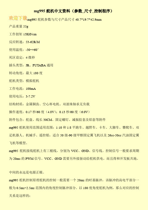
图 2MG 9 9 5舵机外形及相关参数 图 3 机控制示 意图 舵 舵机控制 图如同 3所示 , 3条导线分别是 电源线 、 有 地线 、 控制线 。 从 图 2看出电压介于 4 ~ . , 般取 5 。控制线 的输入是 P . 7 V一 8 2 v WM脉 冲信号 , 为 2 m ([ 周期 0 s ̄ 1频率为 s r )通过调节 占空 比来控制 电机 的转 1 o , e 动 角度 。 当脉冲宽度 为 0 m ~ . s , . s 2 m 时 舵机旋转一 O到 9 。角度变化 5 5 9。 O, 与脉 冲宽度 的变化成正 比。舵 机的输出轴转角 与输 入信号的脉冲宽度 之 间的关 系如 图 4 所示 。 WM的幅值是 5 P V时 , 的输 出轴就会保持在 它 个相对应的角度上 , 无论外界转矩怎样改 变 , 只有提供下一个宽度 的 脉冲信 号时才会 改变输 出角度 到新 的对应 的位置上。
松下PLC步进电机控制例子

! ! !
R42 [ ] TMX 3 10
[ F0 MV, H 4, DT9052 [ F0 MV, H 0, DT9052 [ ED ]
] ]
!=uQ=
!"#$
PLC-2
=O
! uM opO uQ opP
fkqbok^qflk^i =====qo^fkfkd
!"
! m_P uR m_N uN
PLC-2
=P
fkqbok^qflk^i =====qo^fkfkd
!"#$ råáíF=
%= Es NF=
= M= J= NMs
!"#$%&'()*= E^å~äçÖ
!"#$%&'
a)
iba
=EsF
sN= =R ON OFF
sN=
=R
OFF ON
b)
iba
=EsF
sN= =Q Q ON OFF OFF
~F=
!"#$%&'()=EbåÅçÇÉêF= =m_N= !"#$%& =uP= ' !"#$=mi`=
!"# ()*+,
m_N uN uP uM opO uQ opP uR m_P ! ! ! !" vM vO vQ
!"#$%&'
!"#$%&'()*+,-./0123 !"#$%&'()*+$%&!,-./
!"#$%&'()*+,-./0123 !"=EuRF= ÄF= !"#$%&'()*+,
mg995舵机控制

mg995舵机控制Chapter 1: IntroductionThe MG995 servo is a widely used motor in robotic systems due to its high torque, accuracy, and reliability. This chapter provides an overview of the significance and objectives of this paper, along with an introduction to the MG995 servo.1.1 Significance of the StudyThe MG995 servo has gained popularity in various robotic applications, including robotics arm, autonomous vehicles, and aerial drones. Its precise control and robust construction make it suitable for a wide range of tasks. Understanding the principles of controlling the MG995 servo is crucial for designing efficient and reliable robotic systems.1.2 ObjectivesThe objective of this paper is to explore the control methods and principles of the MG995 servo. By delving into the technical aspects and capabilities of this servo, we can gain insights into its potential applications and improve the overall performance of robot systems.Chapter 2: MG995 Servo MechanicsIn this chapter, we focus on the internal mechanics of the MG995 servo. Understanding its structure and principles of operation helps in comprehending its unique control requirements.2.1 Internal StructureThe MG995 servo consists of a DC motor, gears, a potentiometer, and a control circuit. The gear reduction system enhances torquewhile preserving accuracy. The potentiometer provides feedback to the control circuit, allowing for precise position control.2.2 Principles of OperationWhen a control signal is supplied to the MG995 servo, the control circuit adjusts the current flowing through the DC motor. This current, combined with the gear reduction system, generates the desired output torque. The potentiometer provides feedback on the servo's position, allowing for closed-loop control.Chapter 3: Control Methods for MG995 ServoThis chapter focuses on various control methods and techniques used to operate the MG995 servo effectively. We explore both open-loop and closed-loop control approaches.3.1 Open-Loop ControlOpen-loop control involves sending a specific control signal to move the servo to a predetermined position. However, due to external factors such as friction and load variations, open-loop control may result in positional errors. Nevertheless, it is suitable for simple applications where precise positioning is not critical. 3.2 Closed-Loop ControlClosed-loop control incorporates feedback from the potentiometer to continuously adjust the control signal until the desired position is achieved. Proportional-Integral-Derivative (PID) control is a commonly used technique in closed-loop control for MG995 servos. It allows for accurate and stable position control, compensating for external disturbances.Chapter 4: Applications and Future DirectionsThis final chapter discusses the practical applications of MG995 servos in various fields and identifies potential areas for future research and development.4.1 ApplicationsThe MG995 servo finds applications in robotics arms, walking robots, humanoid robots, autonomous vehicles, and aerial drones. It offers precise actuation, enabling these systems to perform complex tasks with high accuracy and reliability.4.2 Future DirectionsFuture research can focus on improving the MG995 servo's performance by exploring advanced control techniques, reducing positional errors, enhancing communication interfaces, and minimizing power consumption. Additionally, exploring the integration of MG995 servos with advanced artificial intelligence algorithms can enable more sophisticated and intelligent robotic systems.In conclusion, the MG995 servo is a versatile and high-performance motor widely used in robotics. This paper provides an overview of its mechanics, control methods, and potential applications. Understanding the control principles of the MG995 servo is crucial for designing efficient and reliable robotic systems. With further advancements, the MG995 servo holds immense potential to revolutionize the field of robotics.Chapter 1: Introduction1.1 Significance of the StudyThe MG995 servo is a crucial component in various fields of robotics, including industrial robotics, humanoid robots, and autonomous vehicles. Understanding the control methods and principles of the MG995 servo is significant as it allows researchers and engineers to optimize its performance, improve the accuracy of robotic systems, and enable them to perform complex tasks efficiently.1.2 ObjectivesThe objective of this paper is to delve into the technical aspects and capabilities of the MG995 servo. By exploring its internal mechanics and control methods, we can gain insights into its potential applications and provide guidelines for efficient and reliable integration of the servo into robotic systems. This paper aims to provide a comprehensive understanding of the MG995 servo, its control principles, and its role in the advancement of robotics.Chapter 2: MG995 Servo Mechanics2.1 Internal StructureThe internal structure of the MG995 servo consists of several key components. These include a DC motor, gear system, potentiometer, and control circuit. The DC motor is responsible for generating the necessary torque to drive the servo's movement. The gear system provides torque amplification and precise motion transmission. The potentiometer serves as a feedback device, constantly measuring the position of the servo, allowing for accurate control. The control circuit processes the control signal and adjusts the electrical current to the motor accordingly.2.2 Principles of OperationThe MG995 servo operates based on the principles of electrical and mechanical systems. When a control signal is applied to the servo, the control circuit adjusts the electrical current flowing through the motor coils. This current generates a magnetic field that interacts with the permanent magnet inside the motor, resulting in rotational motion. The gear system amplifies the torque generated by the motor, allowing for precise movement control. The potentiometer provides position feedback to the control circuit, enabling closed-loop control.Chapter 3: Control Methods for MG995 Servo3.1 Open-Loop ControlOpen-loop control is a basic control method where a control signal is sent to the servo without considering feedback from the potentiometer. While open-loop control is simple to implement, it may result in positional errors due to external factors such as friction and load variations. This control method is suitable for applications where precise positioning is not critical, such as controlling the opening and closing of a robot gripper or adjusting the orientation of a camera.3.2 Closed-Loop ControlClosed-loop control incorporates feedback from the potentiometer, allowing for more accurate position control. Proportional-Integral-Derivative (PID) control is a commonly used technique in closed-loop control for MG995 servos. It continuously adjusts the control signal based on the difference between the desired position and theactual position measured by the potentiometer. By taking into account the history of error and the rate of change, PID control ensures stability and improves the servo's response to external disturbances.Chapter 4: Applications and Future Directions4.1 ApplicationsThe MG995 servo has countless applications in the field of robotics. Its high torque and accurate control make it suitable for tasks that require precise movement and manipulation. In industrial robotics, the MG995 servo can be used to control robotic arms for assembly, handling, and welding operations. In the field of humanoid robotics, it can be employed to control the joints of humanoid robots, enabling them to mimic human movements. Furthermore, in autonomous vehicles and aerial drones, theMG995 servo can be used to control steering mechanisms, camera gimbals, and flight control surfaces.4.2 Future DirectionsFuture research and development of the MG995 servo can focus on several areas. Firstly, advanced control techniques can be explored to improve its performance, such as adaptive control algorithms and nonlinear control methods. Secondly, efforts can be made to reduce positional errors by enhancing the mechanical design and minimizing backlash in the gear system. Additionally, improving communication interfaces and integrating the MG995 servo with advanced artificial intelligence algorithms can enhance its capabilities and enable more sophisticated and intelligent robotic systems. Moreover, research can be conducted to optimize powerconsumption and develop energy-efficient control strategies for the servo.In conclusion, the MG995 servo is a versatile and high-performance motor widely used in robotics. This paper has provided an overview of its internal mechanics, control methods, and potential applications. By understanding the principles of controlling the MG995 servo, researchers and engineers can optimize its performance, improve the accuracy of robotic systems, and enable more efficient and reliable task execution. With further advancements and developments, the MG995 servo holds immense potential to contribute to the advancement of robotics in various fields.。
松下PLC伺服控制案例共50页文档

21、要知道对好事的称颂过于夸大,也会招来人们的反感轻蔑和嫉妒。——培根 22、业精于勤,荒于嬉;行成于思,毁于随。——韩愈
23、一切节省,归根到底都归结为时间的节省。——马克思 24、意志命运往往背道而驰,决心到最后会全部推倒。——莎士比亚
松下PLC伺服控制案例
11、用道德的示范来法律是无私的,对谁都一视同仁。在每件事上,她都不徇私情。—— 托马斯
13、公正的法律限制不了好的自由,因为好人不会去做法律不允许的事 情。——弗劳德
14、法律是为了保护无辜而制定的。——爱略特 15、像房子一样,法律和法律都是相互依存的。——伯克
25、学习是劳动,是充满思想的劳动。——乌申斯基
谢谢!
mg995舵机中文资料(参数_尺寸_控制程序)
mg995舵机中文资料(参数_尺寸_控制程序)
mg995舵机参数与尺寸产品尺寸40.7*19.7*42.9mm
产品重量55g
工作扭矩13KG/cm
反应转速:53-62R/M
使用温度:-30~+60°
死区设定:4微秒
插头类型:JR、FUTABA通用
转动角度:最大180度
舵机类型:模拟舵机
工作电流:100mA
使用电压:3-7.2V
结构材质:金属铜齿、空心杯电机、双滚珠轴承无负载
操作速度:0.17秒/60度(4.8V);0.13秒/60度(6.0V)
附件包含:舵盘、线长30CM、固定螺钉、减振胶套及铝套等附件
mg995舵机使用范围适用范围:1:10和1:8平跑车、越野车、卡车、大脚车、攀爬车、双足机器人、机械手、遥控船,适合50级-90级甲醇固定翼飞机以及26cc-50cc汽油固定翼飞机等模型。
mg995舵机接线舵机上有三根线,分别为VCC、GND、信号线。
控制信号一般要求周期为20ms的PWM信号。
VCC、GND需要另外接驱动给舵机供电,而且得和开发板共地。
中间的永远是电源正极。
mg995舵机控制原理舵机的控制一般需要一个20ms的时基脉冲,该脉冲的高电平部分一般为0.5ms~2.5ms范围内的角度控制脉冲部分。
以180度角度舵机为例,那么对应的控制关系是这样的:。
基于松下PLC脉冲控制机械手系统的设计

工作 过 程 :当机 械 手 处 于初 始 位 置 ( 上 方 位 置 ) 左
时 .按 下 启 动 按 钮 后 ,机 械 手 下 移 至 左 工 作 台 ,夹 紧 工 件
后 . 向 上 回 到 原 点 ;然 后 右 移 ,移 到 位 后 向 下 至 右 工 作
台 ,放 下 工 件 。再 向上 、向 左 回 到 初 始 位 置 ,完 成 一 次 动 作周期 。 机 械 手 的 操 作 方 式 分 为 点 动 、单 步 、单 周 期 和连 续 操 作。 ( )点 动 操 作 :操 作 按 钮 对 机 械 手 的 每 一 种 移 位 运 动 1 单 独 进 行 控 制 。 例如 , 当选 择 上/ 运 动 方式 后 ,按下 启动 下 图 1 气 压 驱 动
3 )气 源 大 于 01 a而 且 小 于 08 a .MP .MP ; 4)外 型尺 寸 :4 e 3 e 4 c 0 mx 5 mx 5 m;
按 钮 。机械 手 右移 。 当选 择 夹 紧/ 松运 动方 式 后 ,按 下 启 放 动 按 钮 ,机 械 手 夹 紧 ;按下 停 止 按 钮 ,机 械 手放 松 。
位 置
输 输 脉 椭号几
方向信号
驱
动
执行 机构包括 手部 、手臂和躯 干 。手部装 在手 臂的前 端 。 根据 夹持对象 的形状 和大小配 备多 种形状 和尺 寸的夹 头 ,
以适 应操 作 的 需 求 .本 文 设 计 采 用 二 指 的 构 造 ,手 爪 部 分 采 用 气 压 驱 动 。示 意 图 如 图 l 示 。 所
用 小 型 可 编 程 控 制 器 实 现 ,选 用 步 进 电动 机 带 动 丝 杠 、螺
母 机 构 驱 动 手 臂 运 动 ,P C 脉 冲 控 制 步 进 电 机 系 统 框 图如 L
松下PLC伺服控制案例

松下PLC伺服控制案例
欢迎来到本次松下PLC伺服控制案例分享。接下来,我们将介绍PLC和伺服控 制的基本概念,并展示松下PLC伺服控制的优势和应用案例。
PLC和伺服控制的简介
PLC(可编程逻辑控制器)和伺服控制都是先进的自动化控制技术。PLC用于 逻辑控制和输入/输出管理,而伺服控制用于实现精确的运动控制。
案例2:家庭自动化中的松下 PLC伺服控制
松下PLC伺服控制可将家庭自动化系统整合为一个智能平台,实现智能家居设 备的远程控制和协同运行,提升居住体验。
案例3:交通领域中的松下PLC 伺服控制
松下PLC伺服控制在交通信号控制和交通系统管理中发挥重要作用,确保交通 流畅、安全和高效。
未来的发展和趋势
随着物联网和人工智能的快速发展,松下PLC伺服控制技术将不断创新和演进, 为各个领域提供更多智能化和自动化的解决方案。
总结和要点
• 松下PLC伺服控制提供高性能和稳定可靠的运动控制解决方案。 • 它在工业、家庭和交通领域都有广泛的应用案例。 • 随着技术的发展,松下PLC伺服控制将继续创新和演进。
松下PLC伺服控制的优势
• 高性能和精度,适用于各种运动控制应用。 • 可编程性和可扩展性,方便用户根据需求进行定制和升级。 • 稳定可靠下PLC伺服控制
通过松下PLC伺服控制技术,工业自动化系统可以实现高精度的生产流程控制和协调,提高生产效率并降低人 力成本。
MG995945995舵机的参考资料剖析
舵机的工作原理:控制信号由接收机的通道进入信号调制芯片,获得直流偏置电压。
它内部有一个基准电路,产生周期为20ms,宽度为 1.5ms的基准信号,将获得的直流偏置电压与电位器的电压比较,获得电压差输出。
最后,电压差的正负输出到电机驱动芯片决定电机的正反转。
当电机转速一定时,通过级联减速齿轮带动电位器旋转,使得电压差为0,电机停止转动。
当然我们可以不用去了解它的具体工作原理,知道它的控制原理就够了。
就象我们使用晶体管一样,知道可以拿它来做开关管或放大管就行了,至于管内的电子具体怎么流动是可以完全不用去考虑的。
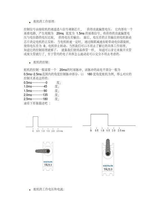
舵机的控制:舵机的控制一般需要一个20ms的时基脉冲,该脉冲的高电平部分一般为0.5ms~2.5ms范围内的角度控制脉冲部分。
以180度角度舵机为例,那么对应的控制关系是这样的:0.5ms--------------0度;1.0ms------------45度;1.5ms------------90度;2.0ms-----------135度;2.5ms-----------180度;请看下形象描述吧:舵机的工作电压和电流:每一款舵机都有自己的参数,如TR213舵机的工作电压是 4.8-7.2V,TR205舵机的工作电压是 4.8-6V,电压不能超过这个范围,否则会很容易烧坏舵机,在不清楚舵机工作电压范围的情况下,建议使用5V给舵机供电。
舵机的工作电流是根据舵机的实际情况而定的,如TR213舵机,在空载的时候电流几乎为0,而在正常负载的情况下,电流在0.5A左右,视实际情况而定。
六足机器人需要18个TR213金属舵机,需要提高的电流大概在8A左右,如果电源功率不够会影响舵机的性能,最常见的现象是,当一个舵机负载的时候,其他舵机会出现混乱,无规律的乱摆。
舵机三根线的区分:信号线接单片机I/O口,由于舵机内部有驱动电路,所以可以直接用普通的单片机I/O口直接控制;电源正极,接输入电源的正极;地线,接输入电源的负极;备注:如果控制部分和电源部分是分开的,两者一定要共地。
- 1、下载文档前请自行甄别文档内容的完整性,平台不提供额外的编辑、内容补充、找答案等附加服务。
- 2、"仅部分预览"的文档,不可在线预览部分如存在完整性等问题,可反馈申请退款(可完整预览的文档不适用该条件!)。
- 3、如文档侵犯您的权益,请联系客服反馈,我们会尽快为您处理(人工客服工作时间:9:00-18:30)。
图 5 接口电路 4.程序设计 4.1 用定时器产生 PW M 波形法 定时中断就是中断程序里面设定中断的次数,每隔一定时间反复 执行中断。它最短定时为 0.5m s,输出高电平时次数乘以定时时间结果 等于 1.5m s 后输出低电平,结果等于 20m s 时再输出高电平,计数器清 零,循环执行前面的程序。把脉宽的可调功能加上去,调节中断的次数, 达到调节脉宽的效果。 具体的程序如图 6。
参考文献 [1]万国江,白占国,王浩然等.洱海近代沉积物中碳氮磷的生物地球 化学记录.地球化学,2000.29:189- 196 [2]万国江.湖泊沉积物 - 水界面地球化学.地球科学基金项目研究 进展(一).北京:地震出版社,1994 [3]张维.红枫湖、百花湖环境特征及富营养化.贵阳:贵州科技出版 社,1999 [4]朱俊等.过程沉积磷的早期成岩作用模型研究.矿物学报,2006.9 [5]王雨春等.贵州红枫湖沉积物磷赋存形态及沉积历史.湖泊科学, 2004.3
参考文献 [1]EvangelosPetroutsos.PLC 从入门到精通.北京:电子工业出版社, 1999 [2]熊有伦.机器人技术基础.武汉:华中科技大学出版社,1996.78- 81 [3]北京创博兴盛机器人技术有限公司“. 未来之星”用户手册.2008 [4]李智辉.基于 A R M 的舵机控制器研究.硕士学位论文.北京:北 京理工大学,2008 [5]张万忠,钱入庭,宋晋等.可编程控制器入门及应用实例.北京: 中国电力出版社,2008 [6]O M R O N 公司提供.C PM 1A 可编程序控制器操作手册.1997 [7]松下公司提供.PF0 可编程序控制器操作手册.2001 [8]T I公司提供.M A X 232 数据手册.2004
(上接第 134 页) 是“活性”相对较大的有机态磷和铁结合态磷,表 明沉积磷的活化再迁移作用显然控制着红枫湖的磷循环。红枫湖各形 态磷在垂直沉积剖面(或沉积时间序列)的分布特征,一方面反映了早 期成岩作用的动力学过程;另一方面,也反Байду номын сангаас了物源输入负荷变化等人 为影响的重要信息。红枫湖有机态磷和铁结合态磷,在埋藏过程中受到 明显的早期成岩作用改造,表层(或近年输入)沉积物有机质的矿化分 解,导致了沉积磷的强烈转化迁移;而吸附态磷、自生磷灰石磷和残留 态磷的变化则是沉积物埋藏过程相对较弱的过程。同时,沉积物有机态 磷和铁结合态磷的剖面分布变化,显然与近年来红枫湖水环境富营养 化演化(人为活动影响)历史相关。
载,响应时间快(约 0.2m s),可带外部负载小。 晶闸管输出型:C PU 通过光耦合使三端双向可控硅通断,以控制外
部交流负载,开路漏电流大,响应时间较快(约 1m s)。 松下型号为 FP0-PLC 32C T 是晶体管输出型,具有 2 路最高可达
10K H z 的脉冲输出,可实现独立控制,互补干扰。2 通道输出时,每通道 最高 5K H z,可用于两轴位置控制。该型号 PLC 具有 PW M 输出功能,它 输出的 PW M 波形周期是固定的几种,占空比可调。从操作手册查输出 电压为 21.6~26.4V ,Y 0、Y 1 的响应时间为不大于 50 微秒,输出的响应 时间满足 PW M 波形程序输出,即电压不符合要求;可通过 PLC 产生 PW M 波形后通过接口电路接到舵机上。选用该型号的 PLC 符合控制 M G 995 舵机要求。
图 4 舵机的输出轴转角与输入信号的脉冲宽度之间的关系 2.P LC 的特性 2.1 PLC 的输出类型 PLC 的输出有继电器输出、晶闸管输出和晶体管输出三种方式。 继电器输出型:C PU 驱动继电器线圈,当触点吸合,外部电源通过 闭合的触点驱动外部负载,其开路漏电流为零,响应时间慢(约 10m s), 可带较大的外部负载。 晶体管输出型:C PU 通过光耦合使晶体管通断,以控制外部直流负
图 1 系统构成图 1.舵机的控制 舵机,顾名思义是控制舵面的电动机,是一种位置伺服的驱动器。 它接收一定的控制信号,输出一定的角度,适用于需要角度不断变化并 可保持的控制系统。主要组成部分:舵盘、减速齿轮组、位置反馈电位计 5k、直流电机、控制电路板等。M G 995 舵机外形及相关参数如图 2:
2.2 PLC 生成 PW M 波形法 (1)PW M 模块,某些 PLC 有专门的产生 PW M 功能。 (2)使用定时器定时生产 PW M 波形,可用 PLC 的定时器定方波高 电平和低电平的时间。循环输出波形就是 PW M 波形。 (3)使用间隔定时器生产 PW M 波形,间隔定时器是一到设定的时 间,就不受扫描周期的影响,中断正在执行的程序,立即转去执行中断 处理子程序。它也是定时高电平和低电平的输出时间,循环执行产生 PW M 波形。 因此用 PLC 控制舵机,就是控制 PLC 输出符合要求的 PW M 波形。 3.接口电路 从实验测量输出高低电平为 22.2V /0.6V ,而舵机输入的 PW M 波形 为一定的脉宽 TTL 电平,高低电平为 0V /5V 。PLC 连接舵机时需要通过 接口电路实现 PLC 输出的高电平 22.2V 转换成 5V ,PLC 输出的低电平 0.6V 转换成 0V 。 该接口电路选用的电压转化芯片是 M A X 232,该芯片包含 2 驱动 器、2 接收器和一个电压发生器电路提供 TIA /E IA -232-F 电平。它能够 把 PLC 输出的 PW M 波形转化成符合舵机输入特性的波形,即把±30V 的电压转化为 0/5V 的电压。M A X 232 实现电平转换时,1.2V 以下属于 低电平,1.7V 以上属于高电平。PLC 输出的 PW M 波形在接入 M A X 232 之前,把直流成分去掉,根据电容的隔直通交作用,在 M A X 232 的输入 端前面加上电容就可实现了,接口电路连接如图 5。
参考文献 [1]殷跃平,张作辰,张开军.我国地面沉降现状及防治对策研究 [J].中国地质灾害与防治学报,2005,16(2):1- 8. [2]张阿根,魏子新.中国地面沉降[M ].上海:上海科学技术出版社, 2005. [3]薛禹群,吴吉春,张云等.长江三角洲(南部)区域地面沉降模拟研 究[J].中国科学,2008,38(4):477- 492. [4]陈崇希,裴顺平.地下水开采—地面沉降数值模拟及防治对策研 究—以江苏省苏州市为例[M ].武汉:中国地质大学出版社,2001. [5]薛禹群.我国地面沉降模拟现状及需要解决的问题[J].水文地 质工程地质,2003(5):1- 4. [6]阎世骏,刘长礼.城市地面沉降研究现状与展望[J].地学前缘(中 国地质大学,北京),1996(3):1- 2.
动角度。当脉冲宽度为 0.5m s~2.5m s 时,舵机旋转-90°到 90°,角度变化
与脉冲宽度的变化成正比。舵机的输出轴转角与输入信号的脉冲宽度
之间的关系如图 4 所示。PW M 的幅值是 5V 时,它的输出轴就会保持在
一个相对应的角度上,无论外界转矩怎样改变,只有提供下一个宽度的
脉冲信号时才会改变输出角度到新的对应的位置上。
图 7 采集 PW M 的上升沿生产 PW M 的程序 5.总结 用定时器产生 PW M 波形法, 通过示波器的测试显示 PW M 波形不 稳定,脉冲宽度经常变化,接上舵机后,手臂会抖动;另中断定时最少只 能定时 0.5m s,脉冲宽度调节时,每次脉冲宽度只能改变 0.5m s,相对于 舵机每次最少都得转 45°,不能实现对舵机的微调。采集 PW M 的边沿 产生 PW M 波形法,通过示波器的测试显示 PW M 波形非常好,上升沿 和下降沿可调性好,脉冲宽度能在 0.5m s~2.5m s 之间任意变换;PW M 波形整体上移峰值减小平均值增大,通过接口转换后接上舵机,能够很 好的控制舵机。
0.引言 PLC 的应用已经成为现代设备的象征,是现代工业控制的主要手 段和重要的基础控制设备之一。PLC 具有稳定、可靠和实时处理能力强 的优点。PLC 利用最基本的逻辑运算、定时、计数等功能进行逻辑控制, 可以取代传统的继电器控制系统,广泛应用于机器人、机电系统和航模 的输出执行机构。PLC 控制机械臂是由 PLC 操作达到我们预定的目标。 机械臂是由舵机关节组成,里面的舵机控制卡来控制具有自由度。控制 机械臂是通过控制舵机来实现。本控制系统是利用松下 FP0-PLC 对 M G 995 舵机控制实现机械臂的动作。该系统主要由 M G 995 舵机、接口 电路、松下 FP0-PLC 三部分构成,如图 1 所示:
(上接第 133 页) 的拟合精度显然较高,为 0.7655867,G M (1,1)曲线 模型预测的精度较低,为 3.454123,在该地面沉降趋势中,L 曲线较能 准确的接近实际沉降。
四、结束语 通过上述理论分析和工程实例测算,结合沉降预测模型的研究,可 得出如下结论:本文中对模型预测的精度最终表达成为 M A PE [6(] 平均 绝对百分误差),M A PE 是可以用于评定模型预测精度的一种重要标 准,为了方便比较,本系统对两种模型采用了同一比较标准;此外,我们 还能看到,L 曲线属于增长型曲线,增长特征依时间变化是线性的,对 “S”型增长规律的拟合预测较适用。用 G M (1,1)模型预测,方法简单,易 于计算(特别是用计算机编程或利用软件计算),而且对原始数据的分 布和个数无严格要求(少到四个数据便可建模),因而适应性强,应用范 围广,既可以用于宏观系统,如经济、社会、人口等,也可以用于微观系 统。
图 2 M G 995 舵机外形及相关参数
图 3 舵机控制示意图
舵机控制图如图 3 所示,有 3 条导线分别是电源线、地线、控制线。
从图 2 看出电压介于 4.8~7.2V ,一般取 5V 。控制线的输入是 PW M 脉
冲信号,周期为 20m s(即频率为 50H z),通过调节占空比来控制电机的转
科技信息
高校理科研究
基于松下 FP0- PLC 的 MG995 舵机控制系统实现
中北大学信息与通信工程学院 蒙清华 王忠庆 刘长明
[摘 要]随着 PLC 在工业控制的广泛应用,基于松下 FP0- PLC 输出波形 PW M 占空比可调的特性设计了对 M G 995 舵机的控制系 统。该系统应用 PLC 定时器触发和采集 PW M 的边沿来通断 PW M 波形的输出,通过接口电路完成 PLC 输出的电平到舵机 T T L 的 电平转换,达到对 M G 995 舵机的控制。实验结果表明,该系统 PW M 脉冲宽度在 0.5m s~2.5m s之间任意变换,实现了角度不断变化 和保持的控制,能够很好的控制 M G 995 舵机,达到系统的控制目标。 [关键词]FP0- PLC PW M M G 995 舵机 M A X 232