海德堡CD102飞达调节(英文版)
海德堡SMCD-102四色胶印机常见故障及排除方法
海德堡SM CD-102四色胶印机常见故障及排除方法资料来源:《广东印刷》2009年第4期作者:王永峰颜勇陈卫家海德堡SM CD-102四色胶印机具有自动化程度高、速度快、性能稳定、安全性能好、精度高、误差小、产品质量可靠等特点。
海德堡四色机的运用减少了印刷次数,提高了生产率和成图效果质量,降低了消耗,在印刷生产中发挥着巨大的作用。
但我们在使用中也常出现一些故障,对此总结了一些解决方法供大家参考。
故障一:机器在生产过程中,CP2000系统故障显示栏显示人体进入安全检测对主传动装置的锁定和吹气管位置错误的蓝色色块,不影响机器运行,当继续工作十分钟左右,机器突然闷车,无法运行,并同时出现开关柜和可信度检测故障。
分析原因及排除:初步判断是吹气管开关引起的,调整吹气管开关位置,机器可以正常运行,但人体进入安全检测对主传动装置的锁定和吹气管位置错误的蓝色显示依然存在,机器运行不到十分钟再次闷车,故障显示和以前一样,所以可以判断此故障不只是由吹气管开关位置引起的。
进一步查找,发现平纸器的吹气管有A、B两个位置。
调整平纸器的吹气管位置,故障排除。
故障二:润版系统的制冷机不制冷。
机器工作正常,各印刷单元同时上脏,查看CP窗发现润版液温度高于设定温度,酒精浓度也达不到设定值,水箱水泵工作正常,各单元上水正常,但水箱内用于降温的压缩机不工作。
造成此类故障的原因有两种:分析原因及排除(一):初步判断上脏原因是压缩机不工作,润版液温度过高,酒精挥发过快,导致酒精浓度过低,只有压缩机重新工作,使润版液温度下降,酒精浓度稳定,上脏问题才能解决。
打开电柜检查,压缩机过载跳闸保护,经检测电路正常,压缩机工作,说明压缩机完好,开关复跳说明压缩机所需电流过大,引起压缩机过载。
仔细检查,水箱上端压缩机散热器表面灰尘和污物较多,可能使压缩机过载的原因,压缩机散热器表面的堆积物严重阻碍散热。
对压缩机散热器表面堆积物清理后,故障排除。
分析原因及排除(二):查找原因发现水箱不制冷,关掉水箱重新开机,水箱制冷机只启动一下就停止工作,把整机关机再重新开机,故障依然。
海德堡速霸CD102胶印机电气控制系统解说

海德堡速霸CD102胶印机电气控制系统解说20世纪80年代初期和末期,海德堡公司先后推出了CPC(Computer Print Control)计算机印刷控制系统和世界首创的用于监测、控制和诊断印刷机的全数字化电子系统——CP Tronic(CP窗)印刷机中央控制系统。
CPC和CP窗的结合使用(如图1所示),大大提高了印刷机操作的简便性和可靠性,使得海德堡胶印机设计更加完善。
20多年来,海德堡C PC系统经过不断改进发展,形成了包括CPC1给墨量和套准电子遥控装置、CPC2印刷质量控制系统、CPC3印版图像阅读器和CPC4自动套准控制装置的系列组件。
1999年,CP窗衍生出了为因特网用户服务的CP2000系统。
该系统将CP窗的全数字化整机遥控和CPC1-04的即时供墨、套准遥控系统整合于一体,不仅保留了CP窗独立于选定文字的图形显示系统,并为最终实现用户服务中心的远程遥控诊断奠定了技术基础。
作为印刷设备电气维修人员,要想在印刷机出现电气故障时快速及时地排除故障、解决问题,就必须了解和熟悉印刷机的电气控制系统。
下面就以我厂2000年引进的标准配置CPC1-04遥控系统和CP窗系统的海德堡Speedmaster(速霸)CD102-4四色对开胶印机为例,分析该机的电气控制系统。
一、CPC1-04遥控系统CPC1-04遥控系统(如图2所示)是海德堡CPC系统的基础,可在带显示屏的控制台上对所有调墨机构和印版滚筒的调整机构进行遥控,并配有光笔(6)、作业存储器(5)和与CP窗匹配的图形等离子监视器(15)。
(10)是墨区LED显示屏和墨量调节按钮。
LED显示屏可显示墨斗辊上墨膜厚度分布,CPC通过电位器把实际墨量位置的数据反馈到LED显示屏上。
按下“+”或“-”按钮即可调节墨斗刀片与墨斗辊的间隙,以增加或减少墨量。
此外,还可以用光笔直接在墨区LED显示屏上预调墨量。
给墨量的数据可通过作业存储器记录到磁盘上,便于以后重印此种产品时调用。
海德堡102系列胶印机递纸牙的调节
海德堡102系列胶印机递纸牙的调节※递纸牙的调节(一)所用工具在对递纸牙进行调节时,需要下述辅助工具:1.刻度盘WLm22 231及其相应的固定装置WLm22 232/1、定位工具WLm22 149;2.测试工具WLm22 1077(件号,包括有两个测试轴及一个测试滚球;(见图一)3.另外,在提供一套递纸滚筒或递纸牙排时,常带有一套可供选择的定位轴(零件号整套)这套定位轴有三对,可供精确选择,其公差情况如(图二):件号件号件号二)操作过程1.安装刻度盘。
2.机器运动至递纸牙与压印滚筒的交换位置204o。
注意:如果递纸牙上安装有补偿器,则在对递纸牙进行的各项调节前将补偿器凸轮置于“0”位。
3.反向转动递纸牙,按图三所示使递纸牙尖与压印滚筒前边缘的间隙为1 mm.在这个位置上安装传动面的齿轮并拧上固定螺钉。
4.拆下传动面及操作面的两个定位轴A(图四),换上图一所示的测试轴WLm22 1077,这个轴比实际定位轴尺寸小。
5.为了调节两个内凸轮连续转动机器至刻度盘读数11 o30′(等于此递纸牙在输纸板上取纸位置超前0 o30′或递纸牙与输纸板成90 o角位置)。
当定位杆接触测试轴时要当心,因为凸轮是松动的!在角度11 o 30′时,定位杆B必须与测试轴A相接触。
6.在内凸轮C与摆体驱动滚球D之间塞人mm的钢片,用凸轮靠紧后将凸轮固定。
7.摆开递纸牙,安装外凸轮E,用测试工具WLm22 1077中的测试滚球F定位,定位后测试滚球在两个凸轮间必须移动灵活并无间隙,紧固外凸轮并安装定位销。
8.取下两个测试轴A WLm221077并安装刚取下的定位轴,再使机器运动至位置11o30′此时应能手动转动定位轴并感到有些阻力。
如果定位轴转动时太松或太紧,则需要选用图二中的定位轴。
9.递纸牙转过在输纸板上取纸位置后,牙排慢慢地靠向止动螺钉A(见图五),此时凸轮与摆体驱动滚球C之间的间隙至少应为mm。
当止动螺钉A由于意外的原因被转动时,必须检查递纸牙排的调节参数。
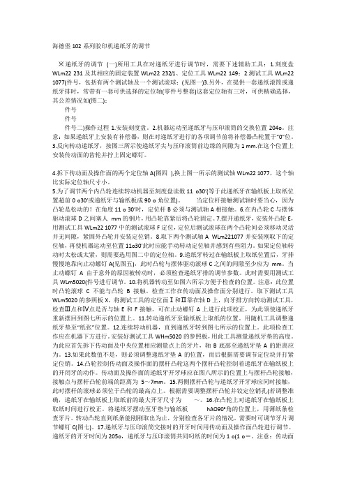
海德堡CD102输纸按键说明和用法精编版
海德堡CD102输纸按键说明和用法海德堡CD102胶印机输纸部分控制台按键如图所示:1、印刷机信息显示屏(MID)2、生产按钮3、停止按键4、加速按键5、减速按键6、正点按键7、安全开关8、紧急停机按钮9、运转按键10、输纸器开按键11、进纸按键12、风漿开关13、着水辊离合键14、走纸故障15、红灯错误显示16、蓝灯错误显示17、扩音器18、麦克风19、音量调节键20、内部通话系统21-22、来去方向移动纸堆挡板23-24、侧挡纸堆位置调节键25-26、主纸堆校正27-28、副纸堆校正29-30、吸气头高度调节31-32吸气头宽度调节33-34输纸器台板定位轮调整1.按键:印刷机信息显示(MID) 显示印刷机数据(印数,机器角度),监测进纸一般错误信息等。
2、按键:生产:在机器运转中按下此键:印刷机自动进入生产模式。
在印刷机停止时按下此键:首先是启动警报。
如果再按下此键,机器自动进入生产模式。
3、按键:停止停止机器。
再机器运行中按下此键:关闭与机器生产有关的所有功能( 除了压缩机)。
4、按键:升高印刷速度按住此键,机器速度将持续上升。
5、按键:降低印速度按下此键,机器速度将持续下降。
中断印刷机提速。
6按键:正点动:启动警报响,然后机器正点动。
需要条件:首先启动飞达的安全开关。
7、按键:安全开关:按下此键:机器只能在该操作面板确认点动模式操作。
(此时发光二极管应闪烁)。
再次按下此键,功能将被解除( 发光二极管停止闪烁)。
8紧急停机按钮:按下此键,机器立即停止,该键被锁定。
转动此钮可解除锁定。
9、按键:运转按下此键,警报声响。
再次按下此键,机器以最低速度运转。
10、按键:飞达开此键控制飞达自动开关。
打开时,发光二极管亮。
11 按键:走纸此键控制走纸开( 此键亮) 和关。
12、按键:风泵开关此键控制风泵开( 此键亮) 和关。
13、按键:靠版水辊合/ 离所有被预选的靠版水辊通过此键可以手动合(此键亮) / 离。
海德堡CD102调牙角度1993年版文档
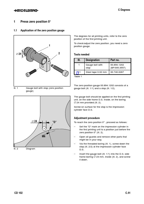
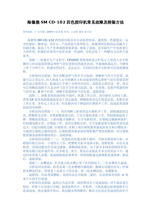
1Press zero position 0°1.1Application of the zero position gaugegauge)The degrees for all printing units, refer to the zero position of the first printing unit.To check/adjust the zero position, you need a zero position gauge.Tools neededTable 1The zero position gauge 00.894.1202 consists of a gauge bolt (Ill. 1/1) and a stop (Ill. 1/2).The gauge bolt should be applied on the first printing unit, on the side frame D.S. inside, on the boring∅ 24 mm provided (Ill. 2).Screw-on surface for the stop is the impression cylinder face D.S.Adjustment procedureTo reach the zero position 0° , proceed as follows:–Set the ”D” mark on the impression cylinder in the first printing unit to a position just before thezero position 0° (Ill. 2).–Open all guards and remove other parts that might be in your way.–Via the threaded boring (Ill. 1), screw down the stop (Ill. 2/2) at the impression cylinder faceD.S.–Insert the gauge bolt (Ill. 1/1) into the D.S. side frame boring ∅ 24 mm, inside (Ill. 2), and screw it down.Ill. 3Obtaining the zero position–Insert a 0.02 mm steel tape (Ill. 3/1) between stop (Ill. 3/2) and gauge bolt (Ill. 3/3).–Carefully rotate the press manually until the steel tape can be removed easily.Note:At this position, the press is at its zero posi-tion 0°.–Remove the zero position gauge, consisting of stop and gauge bolt.Attention!Remove the gauge bolt with stop (zero posi-tion gauge) (Ill. 3) immediately after reaching the mechanical zero position. Danger ofcollision!Ill. 4Press display MIDIf the press display MID does not indicate 000.0, the encoder (HWI) must be adjusted as described in chapter 1.4.1.2Application of the degree wheelIf it is not possible to read the degrees on the press display, e.g. when the press is dead, the degree wheel 00.894.0323 (ill. 5/3) must be mounted.For an exact adjustmet of the degrees and/or gripper timings, the degree wheel can be mounted in printing unit 1 on the feed drum.Attention!The degrees for all printing units refer to the zero position of the first printing unit.Tools neededTable 2Adjustment procedureTo mount the degree wheel (Ill. 5/3) at O.S. by means of a mounting bolt (Ill. 5/2) on the cylinder journal (Ill. 5/1) of the feed drum proceed as follows:–Set the press to position 0° (chapter 1.1).–Open printing unit guard O.S.–Demount the encoder (HWI) (chapter 1.3).–Screw down the mounting bolt (Ill. 5/2) for the degree wheel 00.894.0323 (Ill. 5/3) on the cylin-der journal (Ill. 5/1) of the feed drum.–Fix the degree wheel (Ill. 5/3) on the mounting bolt.–Mount a magnetic stand with pointer and set the pointer to 0° to the degree wheel.1.3Mounting/demounting of the encoder (HWI)The encoder (ill. 6) is the basis for functions that are dependent on speed and degrees.Mounting position:The encoder (HWI) is located at operator’s side of printing unit 1 at the face of the cylinder journal of the feed drum (Ill. 6).To mount and demount or replace the encoder pro-ceed as follows:Demounting the encoder –Switch off the main switch of the press.–Disconnect the plug (Ill. 7/4) of the encoder (HWI).–Remove the plug (Ill. 7/2).–Unscrew the Allen screw (Ill. 7/3).–Remove the encoder (ill. 7/1).Mounting the encoder –Reverse the a.m. procedure to mount the enco-der (HWI).–Turn the shaft of the encoder until the reading000.0 appears on the MID.Ill. 8SupportAttention!Make sure that the spring (Ill. 8/1, 7/5) in the support (Ill. 8/2, 7/6) is not damaged or can jump out.1.4Adjusting the encoder (HWI)Coarse adjustment–Set the press to its zero position 0° as de-scribed in chapter 1.1.Attention!Remove the gauge bolt with stop (zero posi-tion gauge) (Ill. 3) immediately after reachingthe mechanical zero position. Danger ofcollision!–Open two Allen screws (Ill. 9/1, 11/4).–Shift the mounting support (Ill. 9/2, 11/3) untilthe reading 000.0 appears on the MID.Note:If possible, the pin of the HWI should becentered (Ill.11).–Tighten the Allen screws (Ill. 9/1, 11/4).Precision setting–Open the locking nut (Ill. 10/2, 11/2).–Turn the adjusting screw (Ill. 10/1, 11/1) until thereading 000.0 appears on the MID.–Tighten the locking nut (Ill. 10/2, 11/2).Ill. 11Support2Gripper opening and closing times2.1Printing unit IIll. 12Printing unit INote:The values in brackets indicated for thetransfer gripper (swinging transfer gripper)refer to cover guide height 0.4 mm (seechapter C Printing unit 4.3.1).2.2Intermediate printing unitsPrinting units II (VIII)Attention!The degrees for all printing units refer to thezero position of the first printing unit.2.3Last printing unitAttention!The degrees for all printing units refer to thezero position of the first printing unit.2.4Coating unitAttention!The degrees for all printing units and coatingunits refer to the zero position of the firstprinting unit.3Degree tables 3.1FeederTable 33.2Printing units I (V)Table 43.3Printing units VI (VIII)Table 53.4Last unit,printing unit II... VIII or coating unit, sheet transfer to deliveryTable 6。
海德堡飞达调节课件

05
海德堡飞达调节的实际应用案例
案例一:某印刷企业的飞达调节
总结词:高效稳定
详细描述:某印刷企业通过海德堡飞达调节,实现了高效稳定的印刷生产。在调 节过程中,技术人员根据印刷机的特点和纸张特性,对飞达进行了精确的参数设 置,确保了印刷品的质量和效率。
案例二:某出版社的飞达调节
总结词:色彩还原
详细描述:某出版社在印刷过程中,注重色彩还原的准确性。通过海德堡飞达调节,技术人员实现了对印刷机的精准控制, 确保了印刷品的色彩还原度,满足了出版社对色彩的高标准要求。
优化结构设计
通过优化结构设计,提高 设备的抗干扰能力和稳定 性。
加强软件稳定性
通过加强软件稳定性,减 少因软件故障导致的调节 不稳定。
提升调节速度
优化硬件配置
通过优化硬件配置,提高设备的 处理速度和响应速度。
优化算法
通过改进或定制算法,提高数据处 理和计算的效率,从而提升调节速 度。
实现并行处理
通过实现并行处理,提高设备的处 理能力,从而提升调节速度。
海德堡飞达调节课件
CONTENTS
• 海德堡飞达调节的基本知识 • 海德堡飞达调节的操作流程 • 海德堡飞达调节的常见问题及
解决方案 • 海德堡飞达调节的优化建议 • 海德堡飞达调节的实际应用案
例
01
海德堡飞达调节的基本知识
飞达调节的定义
01
飞达调节是指通过调整印刷机的 飞达(即送纸装置)相关参数, 以达到最佳的纸张输送效果和印 刷质量的过程。
提高印刷质量
合理的飞达调节有助于减少纸张在印 刷过程中的位移,确保印刷内容与纸 张位置的准确性,提高印刷品的清晰 度和色彩还原度。
飞达调节的基本原理
CD102操作说明书

A章:安全装置1 印刷机基本安全说明...................... A.1.3 1.1安全说明和一般注释.......................... A.1.31.2 本印刷机的用途............................ A.1.51.3 印刷机操作人员的人身安全保护设备................... A.1.51.4 清洗液,油墨,溶剂和上光液................... A.1.61.5 安全操作印刷机............................ A.1.72. 印刷机的技术规格.......................2.1印刷机的技术规格...........................3. 印刷机上的操作位置......................3.1 印刷机上的操作位置4. 印刷机上配备的操作控制装置..................4.1 电源开关...............................4.2 “紧急停车”(EMERGENCYSTOP)按钮................4.3 “安全”(SAFE)控制旋钮.......................5.CD102印刷机安全防护装置...................5.1 无自动换版装置的印刷机的固定式安全护罩................5..2 无自动换版装置的印刷机的可拆卸式安全护罩...............5..3 配置自动换版装置的印刷机的固定式安全护罩...............5.4 配置自动换版装置的印刷机的可拆卸式安全护罩..............5..5 带有上光单元印刷机的安全护罩.....................5.6 带有双上光单元印刷机的附加安全须知..................5.7 配置紫外线烘干装置的印刷机的安全护罩.................5.8 配置加长收纸装置的印刷机的安全护罩..................5.9 其它安全保护装置...........................6.检查CP2000型印刷机的安全防护装置..............6.1 检查安全防护装置...........................6.2 安全防护装置的各标识意义.......................7.印刷机的操作方式..........................7.1 当按动了“安全”(SAFE)按钮时,印刷机的操作方式.......8. 手动盘车...........................8.1 手动操作;插入盘车杠.........................8.2 手动操作-推入调节轴..........................8.3 手动操作–盘车转动..........................1 印刷机基本安全说明:1.1 安全说明和一般注释:在本印刷机操作手册中包括有三类注释。
海德堡CD102飞达调节(英文版)(学习资料)

turn eccentric screw below the cover with a long screwdriver until paper strip has contact, then turn eccentric screw in opposit direction until the strip has only light contact. Turn a further notch in this direction (the strip has no more contact and can be removed easily). Close the safety bar.
• loosen locking nut of the other forwarding roller
1
• turn adjusting screw until the contact of both forwarding rollers is simultaneous.
• tighten locking nut and check adjusted contact again
Speedmaster 102 Setting pull lay cover height
3 1
0,1 mm
2
1 basic position
2 printing material
- 1、下载文档前请自行甄别文档内容的完整性,平台不提供额外的编辑、内容补充、找答案等附加服务。
- 2、"仅部分预览"的文档,不可在线预览部分如存在完整性等问题,可反馈申请退款(可完整预览的文档不适用该条件!)。
- 3、如文档侵犯您的权益,请联系客服反馈,我们会尽快为您处理(人工客服工作时间:9:00-18:30)。
06/99_CSA-PT
4
Speedmaster 102
Setting of the forwarding rollers
Setting of the contact pressure of a single forwarding roller:
• turn feeder with the handwheel until forwarding rollers (1) touch down on the driving shaft and turn the handwheel half a turn further
• loosen locking nut (2), loosen adjusting screw (3)
• place 0.3 mm thick cardboard strip between adjusting screw (3) and lever (4)
• set adjusting screw to a light contact to the cardboard strip and tighten locking nut (2)
• this forwarding roller is now adjusted
Setting of the simultaneous touchdown of the other forwarding roller:
• turn handwheel until the just set roller has light contact to the driving shaft
• loosen locking nut of the other forwarding roller
• turn adjusting screw until the contact of both forwarding rollers is simultaneous.
• tighten locking nut and check adjusted contact again
Speedmaster 102
Setting of the electronic pull guide monitor
06/99_CSA-PT
106/99_CSA-PT
Speedmaster 102
Setting pull lay cover height
setting the pull lay cover height
• disengage the the safety bar and swing away
• inch press forwards until the pull roll has reached the lowest point
• insert a paper strip (5 mm wide 0,10 mm thick) between pull roll and side lay under the cover
adjustment
1.if paper strip has no contact:
turn eccentric screw below the cover with a long screwdriver until paper strip has contact, then turn eccentric screw in opposit direction until the strip has only light contact. Turn a further notch in this direction (the strip has no more contact and can be removed easily). Close the safety bar.
2. i f contact is too tight:
turn eccentric screw below the cover with a long screwdriver until paper strip slides in, then follow the steps on point 1.
hint: while using heavy cardboard place strip of printing material under the cover and use steps of point 1.
Speedmaster 102
Setting of the sheet arrival control
06/99_CSA-PT check and set sheet arrival control:
• Cut sheet aprox. 100 x 20 cm and disengage side lay. • switch press to safe at feeder, switch feeder on and inch press until the sheet stop fingers are raised up, the inch forwards to 332°.
• set upper dial on zero and align sheet to the front lays
• the control bars appear on the display
adjustment on misalignment:
• turn lower dial anticlockwise to the stop, the control bars will disappear on the display, then turn dial clockwise until one of the control bars reappears on the display.
• continue to turn dial clockwise and count increments (within max. 10 increments the second contol bar must appear on the display).
• on bigger tolerances call service!
• the reflex sensor consists out of two different sensors, one for early and overshooted sheets and one for late sheets.• if the sensors are adjusted they are now on the front edge of the paper
• distance between early and late sheet sensor = 2.6 mm. • To reach final position between the sensors turn dial further 2 1/6 revolutions (= 1.3 mm).
• one full revolution of the dial = 0.6 mm
Speedmaster 102
Setting of the feed drum
• save feeder and inch the press until the locking screws
are easily accessible. Loosen all three locking screws
and inch press further to reach the two dials with the
scale.
• each digit on the scale corresponds to 0.1 mm printing
material thickness.
example: for paper up to 0.1 mm -> position 1
for paper up to 0.2 mm -> position 2
......
• use position 2 as basic position. Any deviations of
material thickness up to +/- 0.1 mm are in tolerance,only
for bigger changes of material thickness change position
of transfer gripper.
• to compensate for any possible backlash of threads
occuring, always turn scale back to position 1 and then
clockwise to the new position.
• after any changes, continue to inch the press until the
locking screws can be reached.
• tighten locking screws , close guard and release the
feeder.
06/99_CSA-PT。