英搏尔_ 隔离DC转换器
艾顿 bypass 隔离自动转换交换器说明书

Unmatched performance and reliabilityBypass isolation ATS Eaton’s bypass isolation automatic transfer switch (ATS) is designed to provide unmatched performance, reliability and versatility for critical standby power applications. Supervisory intelligence is provided by an ATC-900 or ATC-300+ controller, delivering operational simplicity and field adaptability coupled with diagnostic and troubleshooting capabilities. The bypass isolation ATS design is ideal for those applications where the ability to perform maintenance is required without interrupting power to life safety and other critical loads.Product configuration• Automatic operation—ATS and bypass switch• Open and closed transition• 100–1200 A rating• Two-, three- or four-pole• NEMA T 1, 3R• Up to 600 Vac, three- orfour-wire, 60 Hz or 50/60 Hz• Drawout ATS and fixedbypass switch, facilitatingconcurrent maintenance• Service entranceFeatures and benefitsProven performanceand reliability• Automatic and non-automaticoperation modes are availableto provide multiple methods oftransferring the load betweenpower sources• Manual operation allowsunloaded transfer betweenpower sources for allproduct configurations• UL T 1008 Listed short-circuitand short-time (select catalognumbers only) withstandclosing current ratingsmaximize system reliabilitySimplified installationand integration• Factory-configured powersource and load terminalsfor top/bottom cable ingress• Removable enclosure panelsprovide front and rear accessto cable terminal connections• Seismic certified to OSHPD,CBC, IBC and UBCEnhanced safety• Two-door, compartmentalizedconstruction provides steelbarriers, protecting workers• Integral safety interlocksautomatically open the maincontacts prior to the ATSbeing isolated for test orremoved for serviceImproved serviceability• Two-door design eliminatesthe need to scheduleshutdowns for routine test,inspection or maintenanceof the ATS• Drawout design allows theATS to be disconnectedfrom the electrical bus andisolated in cell for regulartesting as prescribed bycode (NFPA T 70, 99, 110)• Testing of the isolated ATScan be performed whilethe bypass switch is in theautomatic or non-automaticmode of operationDesign featuresDual automatic technology Eaton’s bypass isolationtransfer switch design includes an automatic bypass switch and an ATS housed within a single assembly.Regardless of which power switch is actively distributing power, redundant automatic operation provides for a rapid load transfer and restoration of power to life safety and critical loads, eliminating the need for active supervision by qualified personnel.Segmented construction The ATS and automatic bypass switch are housed in separate compartments, with robust steel walls, that isolate the power switches from each other to facilitate ease of maintenance and worker safety. Eachcompartment includes a door with padlockable handle. This design prevents the possibility of inadvertent contact andunnecessary exposure to power cable terminations and energized electrical control components.Drawout ATS and fixed-mounted bypassService personnel can rack-out and isolate the ATS (with compartment door closed) from the electrical bus for routine test or exercise. A Kirk T -key interlock prevents access to the racking mechanism until the load connection has been transitioned to the automatic bypass switch.Opening the compartment door allows the ATS to be completely drawn out of the cell for inspection or maintenance.Safety interlocks prevent rack-out or rack-in of the ATS from the electrical bus with the main contacts closed. The automatic bypass switch is fixed mounted to the electrical bus and stands ready to initiate an automatic load transfer when the ATS is undergoing maintenance.Multi-tap control power transformerSystem voltage can be fieldconfigured via a multi-tap control power transformer (CPT) with quick-disconnect plugs.T ransition to bypass mode When maintenance or testing of the ATS needs to be performed, qualified personnel can easily and quickly transition the load connection between the ATS and automatic bypass switch using door-mounted operator controls fitted with indication lights. The transition occurs in a make-before-break fashion, ensuring continuous power flow to loads.Multiple operation modes Operation is possible in the following modes:• Automatic • Non-automatic •Manual AIn automatic mode, the transfer switch is self-acting, and atransfer is automatically initiated by the intelligent logic controller.In non-automatic mode(optional), a transfer is initiated by the operator using a door-mounted selector switch.In manual mode, a transfer is initiated by the operator using controls mounted directly on the automatic bypass switch or ATS.Alternatively, a transfer can be initiated remotely via an HMi remote annunciator controller.A Manual operation (unloaded) is provided forall product configurations.for top and bottom cable terminationFixed-mounted automatic Drawout ATS can be isolated for test within compartment orand automatic bypassswitch compartments600–1200 A rating (480 V), NEMA 1 enclosure100–400 A rating (480 V), NEMA 1 enclosureFixed-mounted automatic Drawout ATS can within compartmentor completely removedRemoveable optionpanels allow front access for top and bottom cableterminationDrawout ATS removed for bench level inspection/Automatic bypass switch stands ready to transfer load2EATON Bypass isolation automatic transfer switchesStandard enclosure dimensions and weightsDimensions and weights shown are approximate and subject to change. Reference product outline drawings for the latest information.NEMA 1 enclosure NEMA 3R enclosureNEMA 12/4X enclosureTransferswitch rating Device Dimensions in inches (mm)Normal,emergency, loadNeutral A Weight ABCA Neutral connection size listed is for product configuration with a solid neutral. For product configurations with a switched neutral (four-pole), reference the size listed in theEmergency/Load Connection column.B Three-pole product configuration.C Four-pole product configuration.3EATON Bypass isolation automatic transfer switchesEaton is a registered trademark.All other trademarks are property of their respective owners.Eaton1000 Eaton Boulevard Cleveland, OH 44122United States © 2022 EatonAll Rights Reserved Printed in USAPublication No. PA01602019E / Z25954March 2022Product selectionCatalog numbering systemote: N Some catalog number combinations may not be available. For additional information, please contact your local Eaton sales representative.Bypass isolation ATS schematic diagramUL 1008 withstand and closing current ratings (kA)Ampere Device Up to 480 VUp to 600 V Short-circuit (specific circuit Short-circuit (specific circuit SpecificFollow us on social media to get the latest product and support information.。
PI3101Cool—Power60W隔离DC—DC转换器设定行业尺寸和功率密度新基准

络 通 信 、带 电 以 太 网 应 用 和 高 速 服 务 器 平 台 的 终 端 系 统 。 P3 0 I1 1的 直 流 输 入 电 压 范 围 很 宽 ,从 3 7 6V~ 5V,提 供
33V 的 稳 压 输 出 ,输 出 电 流 高 达 1 实 现 了 2 c 4 0 i ) 功 率 密 度 , 现 有 解 决 方 案 提 高 了 3 4 倍 , . 8A, 5W/m (0 W/ 的 n 比 ~ 同 时 板 面 面 积 密 度 也 高 达 l . W /m (0 i ) I1 1将 隔 离 、 压 转 换 和 输 出 稳 压 集 成 在 ~ 个 高 密 度 、 贴 功 6 5 e 15W/ 。P30 n 电 表 率 系 统 封 装 (SP 中 , 面 面 积 只 有 36e 05 . 形 非 常 薄 ,高 度 只 有 67m 02 n 。 P i) 板 . m (.7i ) 外 n . m( .7i) C o- o e ol Pw r系 列 在 专 利 零 电 压 开 关 ( V 拓 扑 技 术 基 础 上 , 用 领 先 的 控 制 芯 片 集 成 技 术 、 进 的 平 面 磁 器 Z S) 使 先
于 技 术 上 一 些 固 有 的 限 制 , 得 电 源 的 发 展 也 受 到 制 约 。 如 果 电 源 系 统 所 占 间 太 多 , 得 增 加 到 终 端 产 品 具 有 使 使
竞 争 优 势 的 其 他 技 术 特 征 就 可 能 会 被 削 弱 或 者 完 伞 忽 略 。 解 决 这 问 题 , 统 设 计 者 一 直 努 力 设 计 一 种 最 佳 类 为 系 型 的分 布式 电源 系 统 以 满 足 系统 需 求 , 时仍 然 保 持 高效 、 靠 、 成 本 的特 点 , 活 地适 应快 速 变 化 的需 求 。 同 可 低 灵
莫尔森DC DC转换器产品说明书
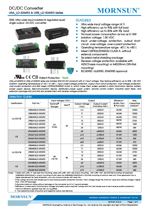
30W,Ultra wide input isolated ®ulated dual/single output,DC/DC converterCB Patent ProtectionRoHSFEATURES●Ultra wide input voltage range (4:1)●High efficiency up to 90%with full load ●High efficiency up to 82%with 5%load●No-load power consumption as low as 0.14W ●Isolation voltage:1.5K VDC●Input under-voltage protection,output short circuit,over-voltage,over-current protection ●Operating temperature range:-40℃to +80℃●Meet CISPR32/EN55032CLASS A,without external components●Six-sided metal shielding package●Reverse voltage protection available with A2S(Chassis mounting)or A4S(35mm DIN-Rail mounting)●IEC60950,UL60950,EN60950approvalURA_LD-30WR3&URB_LD-30WR3series are isolated 30W DC-DC products with 4:1input voltage.They feature efficiency up to 90%,1.5K VDC isolation,operating temperature of -40℃to +80℃,Input under-voltage protection,output short circuit protection,over-voltage protection,over-current protection and EMI meets CISPR32/EN55032CLASS A,which make them widely applied in data transmission device,battery power supply device,tele-comunication device,distributed power supply system,remote control system,industrial robot fields.And extension package A2S and A4S also enable them with reverse voltage protection.Product Characteristic CurveFig.1Apply model :URA2405LD-30W(H)R3(9-18V input voltage )、URA2424LD-30W(H)R3(9-18V input voltage )、URA4805LD-30W(H)R3(18-36V input voltage )Fig.2Apply model :URA2405LD-30W(H)R3(18-36V input voltage )、URA2424LD-30W(H)R3(18-36V input voltage )、URA4805LD-30W(H)R3(36-75V input voltage )、URA2412LD-30W(H)R3、URA2415LD-30W(H)R3、URA4812LD-30W(H)R3、URA4815LD-30W(H)R3Fig.3Apply model :URB2403LD-30W(H)R3、URB2405LD-30W(H)R3、URB4803LD-30W(H)R3、URB4805LD-30W(H)R3Fig.4Apply model :URB2409LD-30W(H)R3、URB2412LD-30W(H)R3、URB2415LD-30W(H)R3、URB2424LD-30W(H)R3、URB4812LD-30W(H)R3、URB4815LD-30W(H)R3、URB4824LD-30W(H)R3All the DC/DC converters of this series are tested according to the recommended circuit(see Fig.5)before delivery.If it is required to further reduce input and output ripple,properly increase the input&output of additional capacitors Cin and Cout or select capacitors of low equivalent impedance provided that the capacitance is no larger than the max.capacitive load of the product.V in0VV in0VDual outp ut:Single outputvoltage(VDC)Cout(µF)Cin(µF)Dual outputvoltage(VDC)Cout(µF)Cin(µF)3.3/5/9220100±5/±12/±1522010012/15/24100±241002.EMC solution-recommended circuitSingle outputFig.6Notes:Part①in the Fig.6is used for EMC test and part②for EMI filtering;selected based on needs.Parameter descriptionModel Vin:24V Vin:48VFUSEChoose according to actual inputcurrentMOV S20K30S14K60C0680µF/50V330µF/100VC1330µF/50V330µF/100VC2 4.7µF/50V 2.2µF/100VC3Refer to the Cout in Fig.5LCM1mH,recommended to useMORNSUN’s FL2D-30-102sCY1、CY21nF/2KVDual outputFig.7Notes:Part①in the Fig.7is used for EMC test and part②for EMI filtering;selected based on needs.Model Vin:24V Vin:48VFUSE Choose according to actual inputcurrentMOV S20K30S14K60C0680µF/50V330µF/100VC1 2.2µF/50V 2.2µF/100VC2 2.2µF/50V 2.2µF/100VC3330µF/50V330µF/100VC4Refer to the Cout in Fig.5LDM1 3.3µHCY1、CY2 2.2nF/400V AC Safety Y Capacitor3.Application of Trim and calculation of Trim resistanceTrim up Trim downApplied circuits of Trim(Part in broken line is the interior of models)Calculation formula of Trim resistance:up: a=VrefVo’-VrefR1R=TaR2R-a2-R3down: a=VrefVo’-VrefR2R=TaR1R-a1-R3R T is Trim resistance,a is a self-definedparameter,with no real meaning.Vo’for the actual needs of the up ordown regulated voltageVout(VDC)R1(KΩ)R2(KΩ)R3(KΩ)Vref(V)3.34.801 2.8712.4 1.245 2.883 2.8710 2.597.500 2.8715 2.51211.000 2.8715 2.51514.494 2.8715 2.52424.872 2.8717.8 2.54.It is not allowed to connect modules output in parallel to enlarge the power5.For more information please find DC-DC converter application notes on Horizontal Package(without heat sink)Dimensions and Recommended LayoutHorizontal Package(with heat sink)DimensionsURA_LD-30WR3A2S&URB_LD-30WR3A2S(without heat sink)DimensionsNotes:1.Packing information please refer to Product Packing Information which can be downloaded from .Horizontal Packing Bag Number:58200035(without heat sink),58200051(with heat sink),A2S/A4S Packing Bag Number:58220022;2.The maximum capacitive load offered were tested at input voltage range and full load;3.Unless otherwise specified,parameters in this datasheet were measured under the conditions of Ta=25℃,humidity<75%RH with nominalinput voltage and rated output load;4.All index testing methods in this datasheet are based on Company’s corporate standards;5.We can provide product customization service,please contact our technicians directly for specific information;6.Products are related to laws and regulations:see"Features"and"EMC";7.Our products shall be classified according to ISO14001and related environmental laws and regulations,and shall be handled byqualified units.Mornsun Guangzhou Science&Technology Co.,Ltd.Address:No.5,Kehui St.1,Kehui Development Center,Science Ave.,Guangzhou Science City,Luogang District,Guangzhou,P.R.China Tel:86-20-38601850-8801Fax:86-20-38601272E-mail:***************。
摩恩孙U6WR3系列6W隔离DC-DC转换器产品说明书

6W,Ultra wide input isolated ®ulateddual/single output,DIP package,DC/DC converte r CBPatent Protection RoHSFEATURES ●Wide input voltage range (4:1)●High efficiency up to 88%●No-load power consumption as low as 0.12W ●Isolation voltage :3K VDC●Operating temperature range:-40℃to +85℃●Input under-voltage protection,output short circuit ,over-current,over-voltage protection●Meet CISPR32/EN55032CLASS A,without external components●International standard pin-out●IEC60950,UL60950,EN60950approvalURF_P-6WR3&URF_P-6WR3series are isolated 6W DC-DC converters with 4:1input voltage.They feature efficiency up to 88%,3000VDC isolation voltage,operating temperature of -40℃to +85℃,solation voltage of 3000VDC,output over-voltage protection and output short circuit protection with the bare component in compliance with CISPR32/EN55032CLASS A;these products are widely used in fields such as industrial control,electric power,instruments and communication.Selection GuideCertificationPart No.Input Voltage (VDC)OutputEfficiency(%,Min./Typ.)②@Full LoadMax.CapacitiveLoad ③(µF)Nominal(Range)Max.①Output Voltage (VDC)Output Current (mA)(Max./Min.)UL/CE/CBURE2405P-6WR324(9-36)40±5±600/078/80680URE2412P-6WR3±12±250/082/84330URE2415P-6WR3±15±200/083/85220URF2403P-6WR3 3.31500/077/792200URF2405P-6WR351200/080/822200URF2409P-6WR39667/083/851000URF2412P-6WR312500/084/86680URF2415P-6WR315400/086/88680URF2424P-6WR324250/085/87680URF4803P-6WR348(18-75)803.31500/077/792200URF4805P-6WR351200/081/832200URF4812P-6WR312500/085/87680URF4815P-6WR315400/086/88680URF4824P-6WR324250/085/87680Notes :1The input voltage shoud not exceed the maximun rating,or it maight cause unrecoverable damages;2Efficiency is measured In nominal input voltage and rated output load;3The capacitive loads of positive and negative outputs are identical.Input SpecificationsItemOperating ConditionsMin.Typ.Max.UnitInput Current (full load /no-load)24VDC Input3.3V output --261/5268/8mAOther output --297/5320/848VDC Input3.3V output --131/4134/7Other output--146/4154/7Reflected Ripple Current24VDC Input --20--mA48VDC Input --20--Input impulse Voltage (1sec.max.)24VDC Input -0.7--50VDC48VDC Input -0.7--100Starting Voltage24VDC Input ----948VDC Input ----18Input Under-voltage Protection24VDC Input 5.5 6.5--48VDC Input1215.5--Starting Time Nominal input&constant resistance load--10--msInput Filter Pi filter Hot PlugUnavailableOutput SpecificationsItemOperating ConditionsMin.Typ.Max.UnitOutput Voltage Accuracy 5%-100%load --±1±3%0%-5%loadSingle output --±1±3Dual output--±2±5Balance of Output Voltage Dual output,balanced load --±0.5±1.5Line Regulation Full load,the input voltage is from low voltage to high voltage Positive output --±0.2±0.5Negative output --±0.5±1Load Regulation ①5%-100%loadPositive output --±0.5±1Negative output --±0.5±1.5Cross Regulation Dual output,main circuit with 50%load,auxiliary circuit with 10%-100%load ----±5Transient Recovery Time 25%load step change --300500µs Transient Response Deviation --±3±5%Temperature Drift Coefficient Full load----±0.03%/℃Ripple&Noise ②20MHz bandwidth,5%-100%load --85120mV p-p Over-voltage Protection Input voltage range 110--160%Vo Over-current Protection Input voltage range 24V output 110220290%IoOthers110140190Short circuit ProtectionInput voltage rangeContinuous,self-recoveryNote:①When testing from 0%to100%load working conditions ,load regulation index of ±5%;②0%-5%load ripple&Noise is no more than 5%Vo.Ripple and noise are measured by “parallel cable”method,please see DC-DC Converter Application Notes for specific operation.General SpecificationsItemOperating ConditionsMin.Typ.Max.Unit Isolation Voltage Input-output,with the test time of 1minute and the leak current lower than 1mA3000----VDC Isolation Resistance Input-output,insulation voltage 500VDC 1000----M ΩIsolation Capacitance Input-output,100KHz/0.1V--1000--pF Operating Temperature Derating if the temperature is ≥71℃(see Fig.1)-40--85℃Storage Temperature -55--125Storage Humidity Non-condensing5--95%RH Pin Welding Resistance Temperature Welding spot is 1.5mm away from the casing,10seconds----300℃Vibration10-55Hz,10G,30Min.along X,Y and ZSwitching Frequency PWM mode--300--KHz MTBFMIL-HDBK-217F@25℃1000----K hoursNote:*This series of products using the technique of reducing frequency.The switching frequency is test at full load;when the load is below 50%,the switching frequency decreases with decreasing load.Physical SpecificationsCasing Material Black flame-retardant heat-proof plastic (UL94V-0)Package Dimensions 31.60*20.30*10.20mm Weight13.00g(Typ.)Cooling methodFree air convectionEMC SpecificationsEMICECISPR32/EN55032CLASS A (Bare component)/CLASS B (see Fig.3-②for recommended circuit)RE CISPR32/EN55032CLASS A (Bare component)/CLASS B (see Fig.3-②for recommended circuit)EMSESD IEC/EN61000-4-2Contact ±4KV perf.Criteria B RS IEC/EN61000-4-310V/mperf.Criteria A EFTIEC/EN61000-4-4±2KV (see Fig.3-①for recommended circuit)perf.Criteria B Surge IEC/EN61000-4-5±2KV (see Fig.3-①for recommended circuit)perf.Criteria B CSIEC/EN61000-4-63Vr.m.sperf.Criteria A Immunities of voltage dip,drop and short interruptionIEC/EN61000-4-290-70%perf.CriteriaBProduct Characteristic CurveOperat ing Temperat ure()℃ Temperature Derating C urveO u t p u t P o w e r P e r c e n t a g e (%)-400407185120806010012040200Safe Operating AreaFig.1Design Reference1.Typical applicationAll the DC/DC converters of this series are tested according to the recommended circuit (see Fig.2)before delivery.If it is required to further reduce input and output ripple,properly increase the input &output of additional capacitors Cin and Cout or select capacitors of low equivalent impedance provided that the capacitance is no larger than the max.capacitive load of the product.SingleVinGND+Vo0VDCCinDC CoutDualV inGND+Vo 0V CinCout DC DC-VoCoutFig.2Vin(VDC)Cin(µF)Cout(µF)24100104810~47102.EMC solution-recommended circuitURE_P-6WR3&URF_P-6WR3:Fig.3-①URE_P-6WR3:URF_P-6WR3:Fig.3-②Notes:Part ①in the Fig.3is used for EMS test and part ②for EMI filtering;selected based on needs.Parameter descriptionURE_P-6WR3Model Vin:24VFUSE Choose according to actual input currentC01000µF/50V C11µF/50VC3Refer to the Cout in Fig.2LDM1 4.7µH CY1、CY21nF/3KVParameter descriptionURF_P-6WR3Model Vin:24V Vin:48V FUSE Choose according to actual input currentC01000µF/50V 680µF/100V C1,C2 2.2µF/50V2.2µF/100VLCM 2.2mH,recommended to use MORNSUN’sFL2D-30-222C3Refer to the Cout in Fig.23.It is not allowed to connect modules output in parallel to enlarge the power4.For more information please find DC-DC converter application notes on Dimensions and Recommended LayoutNote:1.Packing information please refer to Product Packing Information which can be downloaded from .ThePacking bag number of Horizontal package:58210008;2.The max.capacitive load should be tested within the input voltage range and under full load conditions;3.Unless otherwise specified,data in this datasheet should be tested under the conditions of Ta=25℃,humidity<75%RH when inputtingnominal voltage and outputting rated load;4.The recommended unbalance degree of the dual output module load is≤±5%;if the degree exceeds±5%,the product performancecannot be guaranteed to comply with all parameters in the datasheet.Please contact our technicians directly for specific information;5.All index testing methods in this datasheet are based on our Company’s corporate standards;6.The performance indexes of the product models listed in this datasheet are as above,but some indexes of non-standard modelproducts will exceed the above-mentioned requirements,and please directly contact our technicians for specific information;7.We can provide product customization service;8.Products are related to laws and regulations:see"Features"and"EMC";9.Our products shall be classified according to ISO14001and related environmental laws and regulations,and shall be handled byqualified units.Mornsun Guangzhou Science&Technology Co.,Ltd.Address:No.5,Kehui St.1,Kehui Development Center,Science Ave.,Guangzhou Science City,Luogang District,Guangzhou,P.R.China Tel:86-20-38601850-8801Fax:86-20-38601272E-mail:****************。
摩尔晟UWTH1D_QB-100W(H F)R3系列100W隔离DC-DC转换器产品说明书

100W isolated DC-DC converterUltra-wide input and regulated single outputCB Report RoHSCSA62368EN62368BS EN62368IEC62368-1EN50155EN45545FEATURES●Ultra-wide12:1input voltage range:14-160VDC●High efficiency up to90%●Reinforced insulation,I/O isolation test voltage3k VAC●Operating ambient temperature range-40℃to+105℃●Active hold-up control,programmable inputunder-voltage control●Input reverse polarity protection,Inputunder-voltage protection,output over-voltage,over-current,short-circuit protection,over-temperature protection●Industry standard1/4-Brick package●Design to meet AREMA standards●Design to meet UL62368standardsThe UWTH1D_QB-100W(H/F)R3series is a high-performance product specifically designed for a variety of railway applications.The output power can reach at100W.It features wide input voltage of14-160VDC,which is compatible with nominal input type of24V,48V,72V,96V and110V.Meets EN50155standard for voltage fluctuations.The reinforced high insulation3000V AC ensures that the system can still be used safely in5000m high altitude applications.The allowable operating temperature is up to105°C.It integrates multiple protection functions to ensure the safety and high reliability of the system,with functions of remote control and compensation,output voltage adjustment,etc., which perfectly matches the requirements of line loss and special voltage in the application.It is widely used in vehicle-mounted switches, train control systems and associated equipment.Selection GuideCertification Part No.①Input Voltage(VDC)Output Full LoadEfficiency(%)③Min./Typ.Max.CapacitiveLoad(µF)Nominal(Range)Max.②Voltage(VDC)Current(mA)(Max./Min.)CSA/EN/BS EN/IECUWTH1D12QB-100W(H/F)R3110(14-160)160128330/088/907000 UWTH1D15QB-100W(H/F)R3156670/04500UWTH1D24QB-100W(H/F)R3244160/087/891800 UWTH1D28QB-100W(H/F)R3283570/01300UWTH1D48QB-100W(H/F)R3482080/088/901000 UWTH1D54QB-100W(H/F)R3541850/0820 Note:①Use“F/H”suffix for heat sink mounting.We recommend to choose modules with a heat sink for enhanced heat dissipation and applications with extreme temperature requirements;②Exceeding the maximum input voltage may cause permanent damage;③Efficiency is tested at nominal voltage and full load at+25℃ambient;④When UWTH1D_QB-100W(H/F)R3series products input voltage is14V~16.8V,the converter can work100ms at full load.Input SpecificationsItem Operating Conditions Min.Typ.Max.Unit Input Current(full load)24V input voltage24V,28V output--47894902mA12V,15V,48V,54V output--4735484536V input voltage24V,28V output--3157323012V,15V,48V,54V output--3121319348V input voltage24V,28V output--2341239612V,15V,48V,54V output--2315236972V input voltage24V,28V output--1561159712V,15V,48V,54V output--1543157896V input voltage24V,28V output--1184121112V,15V,48V,54V output--11711197Patent ProtectionInput Current (full load)110V input voltage 24V,28V output--10331057mA12V,15V,48V,54V output--10221045Reflected Ripple Current Nominal input voltage--150--Surge Voltage (1sec.max.)-0.7--200VDC Start-up Voltage ----14Start-up Current Nominal 48input voltage,full load----5000mA Start-up Time Nominal input voltage,constant resistance load--50100ms Input Filter LC filterHot PlugUnavailableNo-load Input Power Ctrl pin open or pulled high,DC-DC ON (14-160VDC)-- 1.2 2.0WIdle Input Power Ctrl pin pulled low to -Vin,DC-DC OFF (14-160VDC)--0.71.6Ctrl①Module on Ctrl pin open or pulled high (3.5-12VDC)Module offCtrl pin pulled low to -Vin (0-1.2VDC)Input Under-voltage Protection 1011--VDCUVLO②Operating temperature range,UVLO pin open,module off 10----Operating temperature range,UVLO pin connect to -Vin,module off60----Note:①The Ctrl pin voltage is referenced to input -Vin;②The UVLO pin voltage is referenced to input -Vin,please refer to Fig.9.Output SpecificationsItemOperating ConditionsMin.Typ.Max.Unit Voltage Accuracy Nominal input voltage,0%-100%load----±2%Linear Regulation Input voltage variation from low to high at full load --±0.2±0.5Load Regulation Nominal input voltage,10%-100%load --±0.5±1Transient Recovery Time 25%load step change @25℃----500µs Transient Response Deviation --±3±5%Temperature Coefficient Nominal output voltage,full load ----±0.03%/℃Ripple &Noise ①20MHz bandwidth,10%-100%load--150300mVp-p Trim 90--110%Vo Sense----105Over-temperature Protection Max.Case Temperature --115125℃Over-voltage Protection Input voltage range (14-160V)110--160%Vo Over-current Protection 105160260%IoShort-circuit ProtectionHiccup,continuous,self-recoveryNote:①The “Tip and barrel method”is used for ripple and noise test,for details please refer to Fig.3.General SpecificationsItem Operating Conditions Min.Typ.Max.UnitIsolationElectric Strength Test for 1minute with a leakage current of 5mA maxInput-output 3000----V AC Input-case 2500----Output-case2100----Insulation Resistance Input-output resistance at 500VDC 1000----M ΩIsolation Capacitance Input-output capacitance at 100KHz/0.1V--1100--pF Operating Temperature -40--105℃Storage Temperature -55--125Pin Soldering Resistance TemperatureSoldering spot is 1.5mm away from case for 10seconds ----300Storage Humidity Non-condensing 5--95%RH Switching Frequency PWM mode --175--KHz MTBF IEC 61709@25℃1000----k hours Cooling Test EN60068-2-1Dry Heat EN60068-2-2Damp HeatEN60068-2-30Shock and Vibration Test IEC/EN61373Class B Pollution Level PD3Fire&Smoke Compliance EN45545-2,HL3 Salt Mist Test EN60068-2-11,Ka Cyclic Damp Heat Test EN60068-2,Db variant2 Altitude①5000mLow Temperature Start-up andStorage Test EN60068-1,Ad and Ab Note:①When the altitude is above2000m,the product surface max.temperature must be below105℃.Mechanical SpecificationsCase Material Aluminum alloy case;Black plastic bottom,flame-retardant and heat-resistant(UL94V-0)Dimension Without heat sink57.90x36.80x12.70mm With H heat sink57.90x36.80x25.40mm With F heat sink62.00x56.00x14.50mmWeight Without heat sink79.5g(Typ.) With H heat sink109.5g(Typ.) With F heat sink99.5g(Typ.)Cooling Method Conduction cooling or forced air coolingFree air convection cooling with additional heat sink Electromagnetic Compatibility(EMC)(EN50121-3-2)Emissions CEEN50121-3-2EN55016-2-1150kHz-500kHz99dBuV(see Fig.6for recommended circuit)500kHz-30MHz93dBuV(see Fig.6for recommended circuit)EN55032EN55032-11150kHz-500kHz79dBuV(see Fig.6for recommended circuit)500kHz-30MHz73dBuV(see Fig.6for recommended circuit) RE CISPR16-2-330MHz-230MHz40dBuV/m at10m(see Fig.6for recommended circuit)230MHz-1GHz47dBuV/m at10m(see Fig.6for recommended circuit)1GHz-6GHz47dBuV/m at10m(see Fig.6for recommended circuit)Immunity ESD EN61000-4-2Contact±6kV/Air±8kV perf.Criteria A RS EN61000-4-380–800MHz20V/m800–1000MHz20V/m1400–2000MHz10V/m2000–2700MHz5V/m5100–6000MHz3V/mperf.Criteria A EFT EN61000-4-4±2kV5/50ns5kHz(see Fig.6for recommended circuit)perf.Criteria A Surge EN61000-4-5line to line±1kV(42Ω,0.5μF)line to ground±2kV(42Ω,0.5μF)(see Fig.6for recommended circuit)line to line±1kV(2Ω,18μF)line to ground±2kV(12Ω,9μF)(see Fig.6for recommended circuit)perf.Criteria A CS EN61000-4-60.15MHz-80MHz10V r.m.s perf.Criteria AElectromagnetic Compatibility(EMC)(AREMA)Emissions CECISPR16-2-1150kHz-500kHz79dBuV(see Fig.6for recommended circuit)CISPR16-1-2500kHz-30MHz73dBuV(see Fig.6for recommended circuit)RE CISPR16-2-330MHz-230MHz230MHz-1GHz40dBuV/m at10m(see Fig.6for recommended circuit)47dBuV/m at10m(see Fig.6for recommended circuit)Immunity ESD IEC61000-4-2Contact±6kV/Air±8kV perf.Criteria ARS IEC61000-4-380–1000MHz10V/m160–165MHz20V/m450–470MHz20V/m800–960MHz20V/m1400–2000MHz20V/m2100–2500MHz5V/mperf.Criteria AEFT IEC61000-4-4±2kV5/50ns5kHz(see Fig.6for recommended circuit)perf.Criteria A Surge IEC61000-4-5line to line±2kV(2Ω,18μF)line to ground±2kV(12Ω,9μF)(see Fig.6for recommended circuit)perf.Criteria A CS IEC61000-4-60.15MHz-80MHz10V r.m.s perf.Criteria AMS IEC61000-4-860Hz100A/m(see Fig.6for recommended circuit)perf.Criteria A 60Hz300A/m(see Fig.6for recommended circuit)Typical Performance CurvesRemote Sense Application1.Remote Sense Connection if not usedFig.1Notes:(1)If the sense function is not used for remote regulation the user must connect the+Sense to+Vo and-Sense to-Vo.(2)The connections between Sense lines and their respective power lines must be kept as short as possible,otherwise they may be picking up noise,interference and/or causing unstable operation of the power module.2.Remote Sense Connection used for CompensationFig.2Notes:(1)Using remote sense with long wires may cause unstable output,please contact technical support if long wires must be used.(2)PCB-tracks or cables/wires for Remote Sense must be kept as short as possible.Twisted pair or shielded pairs are suggested for remote compensation and must be kept as short as possible.(3)We recommend using adequate cross section for PCB-track layout and/or cables to connect the power supply module to the load in order to keep the voltage drop below0.3V and to make sure the power supply's output voltage remains within the specified range.(4)Note that large wire impedance may cause oscillation of the output voltage and/or increased ripple.Consult technical support or factory for further advice of sense operation.Design ReferenceAll the DC-DC converters of this series are tested before delivery using the recommended circuit shown in Fig.3.Fig.3CapacitorsvalueOutput voltageC0(µF)C1(µF)C2(µF) 12VDC100µF,voltage≥200V1µF,voltage≥1.2*Vo330µF,voltage≥1.2*Vo 15VDC24VDC28VDC48VDC54VDC2.Typical application1.Mornsun EMC circuit is recommended,otherwise please ensure that at least a100µF electrolytic capacitors is connected at the input in order to ensure adequate voltage surge suppression and protection.2.Output ripple can be further reduced by appropriately increasing the output capacitor values C3and/or by selecting capacitors with a low ESR(equivalent series resistance).Also make sure that the capacitance is not exceeding the specified max.capacitance load value of the product.3.The UVLO pin can adjust the point of input under-voltage protection by the external resistance RUVLO.Please refer to Fig.9for the value of RUVLO,if the pin is left open,the under-voltage protection point is11V.4.Ctrl current-mode logic recommended circuit design refer to fig.4.Fig.4Components Value Recommended Component R010K--C30.1µF voltage≥25VQ1Ic≥10mA voltage≥30V Note:S1pin open,DC-DC ON.3.Trim Function for Output Voltage Adjustment (open if unused)Fig.5Trim resistor connection (dashed line shows internal resistor network)Calculation formula of Trim resistance:322T R a R R *a =R :up Trim -- 2.5-Vo R *2.5=a 1311T *=R :down Trim R bR R b --5.2R *)5.2o V (=b 2-Note :a ,b:self-defined parameter ,round to the nearest hundredth R T [k Ω]:Resistance of Trim.Vo:Output voltage change.V ref [VDC]:Reference voltage.Vo Res 12(VDC)15(VDC)24(VDC)28(VDC)48(VDC)54(VDC)R1(K Ω)1114.3524.828.85461R2(K Ω) 2.87 2.87 2.87 2.87 2.94 2.94R3(K Ω)20.220.223.123.118.218.2Practical Example trim up -10%for 12V output:53.9=5.287.2*)5.28.10(=b -ΩK 113.51=2.2053.91111*53.9=R T --R T according to E24≈51k ΩPractical Example trim up +10%for 12V output:57.2=5.22.1311*5.2=a -ΩK 386.4=2.2057.287.287.2*57.2=R T --R T according to E24≈4.3k Ω4.EMC compliance circuit1.The anti-reverse connection circuit is composed of a circuit breaker and a diode D1.The withstand voltage of the diode D1mustbe greater than 250V;2.The EMC filter part is composed of modular circuits.Please refer to Figure 6for recommended circuits and parameters.Self-built circuits can also be used;3.Resistor RUVLO is used to adjust the input under-voltage protection point.Refer to Figure 9for the value.Fig.6Matching Power output voltageC omponents ValueC4C2C1CY4,CY5,CY6D112V 330µFVoltage ≥200V330µFVoltage ≥1.2*Vo1µFVoltage ≥1.2*Vo3300pF /400V AC Y1safety capacitor20AVoltage ≥200V15V 24V 560µFVoltage ≥200V28V 48V 54V BreakerThe Breaker value varies with different power modules and must be selected in accordance with the specified input current of the corresponding power converter,but not exceeding the filter specifications.Note:A ferrite core on the power lines and load lines can ensures a better EMI test margin.EMC FilterComponentsValue Recommended ComponentC60.1µF Voltage ≥630V C80.22µF Voltage ≥250V C9 2.2µF Voltage ≥250V LCM1≧2mH FL2D-A2-202LCM2≧4mH COMMON MODE,≧4mH,35m Ω,-40to +125℃Ø1.2mm×24Ts LDM10.47µH Shielding Inductive LDM2150µH Differential MODE,150uH ±35%,30m Ω,-40to +125℃Core T10*6*4,Ø0.5mm×25TsCY1,CY22200pF /400V AC Y1safety capacitor CY31000pF /400V ACY1safety capacitorMOV17D221KVaristorNote:The emc filter recommended to use MORNSUN P/N:FC-C08D.Surge standardComponentsValue Recommended Component line to line ±1KV (42Ω,0.5μF)line to ground ±2kV (42Ω,0.5μF)C0100µF Voltage ≥250VC10,C11----line to line ±1KV (2Ω,18μF)line to ground ±2kV (12Ω,9μF)C0,C10100µF Voltage ≥250VC11----line to line ±2KV (2Ω,18μF)line to ground ±2kV (12Ω,9μF)C0,C10,C11100µFVoltage ≥250V5.Hold-up time setup capacitorFig.7Recommended circuit and PCB layout for hold-up timeThe hold-up time capacitor CExt.Cap is used to hold the output when the input power off.Note:1.If there is no requirement for the hold-up time,no additional capacitor CExt.Cap is required;2.For the hold-up time of 10ms and 30ms,please refer to table blow;3.Vq is Start-up voltage.Po (W)100Vin (V)2436487296110V q (V)13.219.526.940.353.461.1C Ext.Cap (µF)△t:10ms470470470470470470△t:30ms1410141014101410141014106.Recommended circuit for multi-module parallel redundant designFig.8Note:1.The function of capacitor C1,C2is filtering.It is used for margin design and cannot be used to increase power;2.The diodes D2and D3are used to protect the power module.In actual use,the user can choose the parameters of the diode or MOSFET according to the output current;3.Because the output impedance of the two modules is different,the output power of each module cannot be guaranteed to be equal;Pload =P1+P2<Pmax (100W).7.UVLO Function and R UVLO ValuesThe products with an ultra-wide input voltage range,covering a variety of nominal input voltages.Set the input under-voltage point adjustable function for different input systems,connect a resistor between UVLO pin and -Vin,adjust the under-voltage point of the product by adjusting the resistor value.Fig.9UVLO values for various nominal input voltage and R UVLO tableNominal input voltage (V)2436487296110Starting Voltage (V)13.219.526.940.353.461.1Shutdown Voltage (V)11.216.723.334.846.353.1UVLO setup resistance (K Ω)open15056.118.35.61.5UVLO setup calculation100nF/50V/0805Calculation formula of R UVLO setup resistance :20-c-182c*182=R UVLO 6.45-V 1272.35=c shutdown Note:c:self-defined parameter.R UVLO (K Ω):UVLO setup resistance.V shutdown:UVLO shutdown voltage.8.For additional information please refer to DC-DC converter application notes on Dimensions and Recommended Layout(without heat sink)Note:1.For additional information on Product Packaging please refer to .Packaging bag number:58010113(UWTH1DxxQB-100WR3);58220017(UWTH1DxxQB-100WHR3);58200069(UWTH1DxxQB-100WFR3);2.The maximum capacitive load offered were tested at input voltage range and full load;3.Unless otherwise specified,data in this datasheet should be tested under the conditions of Ta=25℃,humidity<75%RH with nominal inputvoltage and rated load;4.All index testing methods in this datasheet are based on our company corporate standards;5.Product customization is available,please contact below email directly for specific needs;6.Products are related to laws and regulations:see"Features"and"EMC";7.Our products shall be classified according to ISO14001and related environmental laws and regulations,and shall be handled byqualified units.Mornsun Guangzhou Science&Tech nolo gy Co.,Ltd.Address:No.5,Kehui St.1,Kehui Development Center,Science Ave.,Guangzhou Science City,Huangpu District,Guangzhou,P.R.ChinaTel:86-20-38601850Fax:86-20-38601272E-mail:***************。
DC DC转换器 URB_MT-3WR3系列

3W,Ultra wide input isolated®ulated singleoutput DC/DC converterCB Patent Protection RoHSFEATURES●Ultra wide input voltage rang (4:1)●High efficiency up to 84%●No-load power consumption as low as 0.10W ●Isolation voltage:1.5K VDC●Input Under-voltage Protection ,outputshort-circuit protection ,over-current protection ●Operating temperature range:-40℃to +85℃●International standard pin-out●IEC60950,UL60950,EN60950approvalURB_MT-3WR3series products are of 3W output power,extremely wide range of voltage input of 9-36VDC,18-75VDC,isolation voltage of 1500VDC,Input Under-voltage Protection,output short circuit protection,over-current protection,these products are widely used in fields such as industrial control,electric power,instruments and communication.Selection GuideCertificationPart No.Input Voltage (VDC)OutputEfficiency ②(%,Min./Typ.)@Full LoadMax.Capacitive Load(µF)Nominal (Range)Max.①Output Voltage (VDC)Output Current (mA)(Max./Min.)--URB2403MT-3WR324(9-36)403.3728/073/752200UL /CE/CBURB2405MT-3WR35600/078/802200--URB2409MT-3WR39333/078/801000UL/CE/CBURB2412MT-3WR312250/080/82680URB2415MT-3WR315200/081/83470URB2424MT-3WR324125/080/82100CEURB4803MT-3WR348(18-75)803.3728/073/752200URB4805MT-3WR35600/077/792200URB4812MT-3WR312250/080/82680URB4815MT-3WR315200/082/84470URB4824MT-3WR324125/080/82100Notes:①Exceeding the maximum input voltage may cause permanent damage ;②The efficiency value is measured in the input nominal voltage and output rated load.Input SpecificationsItemOperating Conditions Min.Typ.Max.UnitInput Current (full load /no-load)24VDC input series nominal input voltage3.3V Output --134/4138/7mA Others --154/4161/748VDC input series nominal input voltage3.3V Output --67/469/7Others--77/482/7Reflected Ripple Current Nominal 24VDC input series --120--Nominal 48VDC input series --60--Surge Voltage (1sec.max.)Nominal 24VDC input series -0.7--50VDC Nominal 48VDC input series -0.7--100Starting VoltageNominal 24VDC input series ----9Nominal 48VDC input series ----18Input under-voltage protection Nominal 24VDC input series 5.5 6.5--Nominal 48VDC input series1315.5--Starting Time Nominal input voltage &constant resistance load--10--ms Input FilterC filterCtr l*Module turn-onCtrl pin floating or connected to TTL highlevel(3.5-12VDC)Module turn-offCtrl pin connected to GND or low level(0-1.2VDC)Input current when switched off--610mAHot PlugUnavailableNote:*The voltage of Ctrl pin is relative to input pin GND.Output SpecificationsItemOperating ConditionsMin.Typ.Max.UnitOutput Voltage Accuracy --±1±3%Line Regulation Full load,the input voltage is from low voltage to high voltage --±0.2±0.5Load Regulation 0%-100%load--±0.5±1Transient Recovery Time 25%load step change,nominal input voltage --300500µs Transient Response Deviation --±3±5%Temperature Coefficient Full load----±0.03%/℃Ripple &Noise*20MHz bandwidth ,5%-100%load --30120mV p-p Over-current Protection Input voltage range --150250%Io Short circuit ProtectionHiccup protectionNote:*Ripple and noise are measured by “parallel cable”method,please see DC-DC Converter Application Notes for specific operation.0%-5%load ripple&Noise is no more than 5%Vo.General SpecificationsItemOperating ConditionsMin.Typ.Max.Unit Insulation Voltage Input-output,with the test time of 1minute and the leak current lower than 1mA 1500----VDC Insulation Resistance Input-output,insulation voltage 500VDC 1000----M ΩIsolation Capacitance Input-output,100KHz/0.1V --1000--pFOperating Temperature see Fig.1-40--+85℃Storage Temperature -55--+125Casing Temperature Rise Ta=25℃,nominal input voltage,full load output --+40--Pin Welding Resistance Temperature Welding spot is 1.5mm away from the casing,10seconds ----+300Storage HumidityNon-condensing 5--95%RH Reflow Soldering Temperature Peak temp.≤245℃,maximum duration time ≤60s at 217℃.For actual application,please refer to IPC/JEDEC J-STD-020D.1.Vibration10-55Hz,10G,30Min.along X,Y and ZSwitching Frequency*PWM Mode--350--KHz MTBFMIL-HDBK-217F@25℃1000----K hoursNote:*This series of products using lower frequency technology,the switching frequency value is the test value in full load,when the load is reduced to 50%or less,the switching frequency decreases with decreasing load.Physical SpecificationsCasing Material Black flame-retardant heat-proof plastic Dimensions 19.20*18.10*10.16mm Weight3.5g(Typ.)Cooling MethodFree air convectionEMC SpecificationsEMICECISPR22/EN55022CLASS B (see Fig.3-②for recommended circuit)RE CISPR22/EN55022CLASS B (see Fig.3-②for recommended circuit)EMSESD IEC/EN61000-4-2Contact ±4KV perf.Criteria B RS IEC/EN61000-4-310V/mperf.Criteria A EFT IEC/EN61000-4-4±2KV (see Fig.3-①for recommended circuit)perf.Criteria B Surge IEC/EN61000-4-5line to line ±2KV (see Fig.3-①for recommended circuit)perf.Criteria B CSIEC/EN61000-4-63Vr.m.sperf.Criteria A Immunities of voltage dip,drop and short interruptionIEC/EN61000-4-290%,70%perf.Criteria BProduct Characteristic CurveOperating Temperature()℃Temperature Derating CurveO u t p u t P o w e r P e r c e n t a g e (%)-400407185120806010012040200Safe Operating AreaFig.1Design Reference1.Typical applicationAll the DC/DC converters of this series are tested according to the recommended circuit (see Fig.2)before delivery.If it is required to further reduce input and output ripple,properly increase the input &output of additional capacitors Cin and Cout or select capacitors of low equivalent impedance provided that the capacitance is no larger than the max.capacitive load of the product.VinGND+Vo0VDCCinDC CoutFig.2Vn Cin Cout 24VDC 100µF 10µF 48VDC10µF-47µF10µF2.EMC solution-recommended circuitVi nGND+Vo0VDC/DCLOADC2LDM1②MOVFUSE①C1CY1C3C0+Vi nGNDFig.3Notes:Part ①in the Fig.3is used for EMS test and part ②for EMI filtering;selected based on needs.Parameter descriptionModel Vin:24V Vin:48V FUSE Choose according to actual input currentMOV S20K30S14K60C0680µF/50V 680µF/100V C1,C2 4.7µF/50V4.7µF/100VC3Refer to the Cout in Fig.2LDM112µH CY11nF/2KV3.It is not allowed to connect modules output in parallel to enlarge the power4.For more information about Mornsun EMC Filter products,please visit todownload the Selection Guide of EMC FilterDimensions and Recommended LayoutNC:Pin to be isolated from circuitryNotes:1.Packing information please refer to Product Packing Information which can be downloaded from .TubePacking Bag Number:58010114,Reel Packing Bag Number:58010115;2.The max.capacitive load should be tested within the input voltage range and under full load conditions;3.If the product needs to be cleaned after welding,please wait to completely dried before electrical use it;4.Unless otherwise specified,parameters in this datasheet were measured under the conditions of Ta=25℃,humidity<75%RH with nominalinput voltage and rated output load;5.All index testing methods in this datasheet are based on our Company’s corporate standards;6.We can provide product customization service,please directly contact our technicians for specific information;7.Specifications of this product are subject to changes without prior notice.Mornsun Guangzhou Science&Technology Co.,Ltd.Address:No.5,Kehui St.1,Kehui Development Center,Science Ave.,Guangzhou Science City,Luogang District,Guangzhou,P.R.China Tel:86-20-38601850-8801Fax:86-20-38601272E-mail:***************。
1W超薄隔离型DCDC模块及其应用
1W超薄隔离型DC/DC模块及其应用豆豆网技术应用频道 2009年04月23日【字号:小中大】收藏本文关键字:电平逆变器电源适配器基站电池LabView为提高通信设备或装置在信号传输中的抗干扰能力,提高通信的可靠性及满足一些仪表、仪器在复杂环境中的测量精度、提高测量的可靠性,往往在其部分电路或器件上采用了输出稳压的隔离型电源模块供电。
这样不仅提高了电源的输出电压精度、减少纹波噪声电压;并且,由于采用了不共地的隔离电源,可以有效地抑制电磁干扰,消除接地环路的干扰,保护系统电路免受外部网络的影响。
在便携式仪器、仪表及通信装置中,采用超薄隔离型DC /DC模块,不仅占PCB面积小,并且可靠性高,是最佳的选择。
2008年,广州金升阳公司在DC/DC模块上有新的突破,开发出1W超薄隔离型DC/ DC模块系列。
该系列为定压输入,有非稳压输出及稳压输出两类。
本文介绍该系列中定压输入、稳压输出的1W超薄隔离型DC/DC模块,其型号为IF0505RN/RT-1W。
型号中前一个05的意思是输入电压,后一个05的意思是输出电压。
DC/DC电源模块IF0505RN/RT-1WIF0505RN/RT-1W是一种额定功率为1W、定压5V输入、单路5V稳压输出、隔离电压为3000VDC的DC/DC电源模块。
型号中有RN的为DIP封装,有RT的是贴片或SMD 封装。
该模块的主要特点:● 模块体积小,厚度超薄,仅4.5mm;● 输出电压精度高,可达±3%;● 隔离电压高达3000V,并且隔离电容小,仅为25pF;● 无须外部元器件;● 具有输出短路保护,短路排除后能自动恢复;● 输出纹波电压低,为传统的50%,其典型值为10mVp-p;● 温度稳定性高,温漂最大值为0.03%/℃;● 有DIP及SMD两种封装;● 工作温度范围为工业级,-40~+85℃;● 符合RoHS指令要求。
为提高输出电压精度及减小输出纹波、噪声电压,模块内还增加了一个低压差线稳压器(LDO),使性能进一步提高,其结构框图如图1所示。
MORNSUN VCB48_EBO-100WR3 100W 隔离 DC-DC 转换器 产品说明书

100W isolated DC-DC converterWide input and regulated single outputPatent Protection RoHSFEATURES●Wide input voltage range:36-75VDC ●High efficiency up to 93%●I/O isolation test voltage 1.5K VDC●Operating ambient temperature range:-40℃to +100℃●Input under-voltage protection,output short circuit,over-current,over–voltage protection,over-temperature protection ●Industry standard package:1/8brick ●Meet IEC/UL/EN62368standardVCB48_EBO-100WR3series of isolated 100W DC-DC converter products with an wide 2:1input voltage range.They feature efficiencies up to 93%,input to output isolation is tested with 1500VDC and the converter safety operate ambient temperature of -40℃to +100℃,input under-voltage protection,output over-voltage,over-current,short-circuit protection,over-temperature protection.They are ideally and widely used in applications such as industrial control,electric power,instruments and communications.Selection GuideCertificationPart No.Input Voltage (VDC)OutputFull LoadEfficiency ②(%)Min./Typ.Capacitive Load (µF)Max.Nominal (Range)Max.①Voltage (VDC)Current(A)Max./Min.--VCB4805EBO-100WR348(36-75)75520/090/926000VCB4812EBO-100WR348(36-75)75128.3/091/932000VCB4815EBO-100WR348(36-75)7515 6.67/091/932000VCB4824EBO-100WR348(36-75)7524 4.17/090/921000VCB4828EBO-100WR348(36-75)75283.57/090/921000Notes :1Exceeding the maximum input voltage may cause permanent damage;2Efficiency is measured in nominal input voltage and rated output load.Input SpecificationsItemOperating Conditions Min.Typ.Max.Unit Input Current (full load /no-load)Nominal input voltage--2264/202315/30mA Reflected Ripple Current --30100Surge Voltage (1sec.max.)-0.7--80VDC Start-up Voltage ----36VDC Start-up Current----5A Input Under-voltage Protection 2629--VDC Start-up Time Nominal input voltage &constant resistance load ----100msInput Filter πfilterHot PlugUnavailableCtrl①Module onCtrl pin open or pulled high (TTL 3.5-12VDC)Module offCtrl pin pulled low to GND (0-1.2VDC)Input current when off--310mANote:①The Ctrl pin voltage is referenced to input GND.Temperature Derating CurveVCB4805EBO-100WR3(Vin=48V )VCB4812EBO-100WR3(Vin=48V )VCB4815EBO-100WR3(Vin=48V )VCB4824EBO-100WR3(Vin=48V )VCB4828EBO-100WR3(Vin=48V )Remote Sense Application1.Remote Sense Connection ifnot usedNotes :(1)If the sense function is not used for remote regulation the user must connect the +Sense to +Vo and -Sense to 0V at the DC-DC converter pins and will compensate for voltage drop across pins only.(2)The connections between Sense lines and their respective power lines must be kept as short as possible,otherwise they may be picking up noise,interference and/or causing unstable operation of the power module.2.Remote Sense Connection Notes:(1)Using remote sense with long wires may cause unstable output,please contact technical support if long wires must be used.(2)PCB-tracks or cables/wires for Remote Sense must be kept as short as possible.Twisted pair or shielded wairs are suggested for remote compensation and must be kept as short as possible.(3)We recommend using adequate cross section for PCB-track layout and/or cables to connect the power supply module to the load in order to keep the voltage drop below 0.3V and to make sure the power supply's output voltage remains within the specified range.(4)Note that large wire impedance may cause oscillation of the output voltage and/or increased ripple.Consult technical support or factory for further advice of sense operation.1.Ripple &NoiseAll the DC-DC converters of this series are tested before delivery using the recommended circuit shown in Fig.1.Fig.1CapacitorsvalueOutput voltageC0C1C2C35VDC 100uF/100V1uF/50V10uF/50V330uF/63V12VDC 15VDC 24VDC28VDC2.Typical applicationWe recommended using Mornsun’s EMC circuit,otherwise please ensure that at least a 100μF electrolytic capacitors is connected at the input in order to ensure adequate voltage surge suppression and protection.Input and/or output ripple can be further reduced by appropriately increasing the input &output capacitor values Cin and Cout and/or by selecting capacitors with a low ESR (equivalent series resistance).Also make sure that the capacitance is not exceeding the specified max.capacitive load value of the product.0VFig.2Capacitorsvalue Output voltageCin Cout5VDC100uF/100V 330uF/63V12VDC 15VDC 24VDC28VDC3.EMC compliance recommended circuitFig.3C01470uF/100V (electrolytic capacitor)C02100uF/100V (electrolytic capacitor)C03330uF/63V (electrolytic capacitor)C1,C2,C3,C4 4.7uF/100V CY1,CY2,CY3,CY42.2nF/2KVLCM12.2mH,recommended to use MORNSUNFL2D-30-222Fig.4C01470uF/100V (electrolytic capacitor)C02100uF/100V (electrolytic capacitor)C03330uF/63V (electrolyticcapacitor)C1,C2,C3,C4,C5,C6 4.7uF/100V CY1,CY2,CY3,CY4,CY5,CY62.2nF/2KVLCM1 2.2mH,recommended to use MORNSUNFL2D-30-222LCM21.0mH,recommended to use MORNSUNFL2D-30-1024.Trim Function for Output Voltage Adjustment (open if unused)Trim up Trim downTRIM resistor connection (dashed line shows internal resistor network)Calculating Trim resistor values:Trim up)(22.10%511%225.1%)100(11.5Ω⎪⎭⎫ ⎝⎛-∆-∆∆+=k V R nom T Trim down)(22.10%511Ω-⎪⎭⎫ ⎝⎛∆=k R TWhen the output voltage is 12V,the up-regulated voltage is +10%,that is,the output voltage set to 13.2V:10100*122.1312%=-=∆ΩK 48922.1010511-10*225.1)10100(*12*11.5R T =-+=When the output voltage is 12V,the down-regulated voltage is -10%,that is,the output voltage set to 10.8V:10100*128.1012%=-=∆ΩK 88.4022.1010511R T =-=5.Hot Test PointThe thermal element is installed on the top surface of the product and dissipates heat to the surrounding environment through conduction,convection and radiation.Sufficient heat dissipation conditions should be provided to ensure the reliable operation of the product.By measuring the temperature of the thermal test point ①in Fig.5,it can be verified whether the heat dissipation conditions are met.Fig.56.The products do not support parallel connection of their output7.For additional information please refer to DC-DC converter application notes on ①Note:The temperature of the hot test point ①cannot exceed 130℃,otherwise the product will trigger protection due to excessive temperature and cannot work normally.Dimensions and Recommended LayoutNote:1.For additional information on Product Packaging please refer to .Packaging bag number:58210119;2.The maximum capacitive load offered were tested at input voltage range and full load;3.Unless otherwise specified,parameters in this datasheet were measured under the conditions of Ta=25℃,humidity<75%RH with nominalinput voltage and rated output load;4.All index testing methods in this datasheet are based on company corporate standards;5.We can provide product customization service,please contact our technicians directly for specific information;6.Products are related to laws and regulations:see"Features"and"EMC";7.Our products shall be classified according to ISO14001and related environmental laws and regulations,and shall be handled byqualified units.Mornsun Guangzhou Science&Technology Co.,Ltd.Address:No.5,Kehui St.1,Kehui Development Center,Science Ave.,Guangzhou Science City,Huangpu District,Guangzhou,P.R.China Tel:86-20-38601850Fax:86-20-38601272E-mail:***************。