蓝梅主编 给排水科学与工程专业英语部分课文翻译中文版
给水排水专业英语翻译

《给水排水专业英语》Lesson 1specif ic yield[spə'sifik][ji:ld] 单位产水量mass curve累积曲线capita l investment投资recurring natura l event['nætʃərəl] 重现历史事件subter ranea n [sʌbtə'reiniən] 地下的ground water地下水surfac e water地表水tap [tæp]开关、龙头;在…上开空(导出液体)swampl and ['swɔmplænd] n. 沼泽地;沼泽地带capill ary [kə'piləri] n. 毛细管adj. 毛状的,毛细管的hygro- [词头] 湿(气),液体hygros copic [,haigrəu'skɔpik] adj. 易湿的,吸湿的hygros copic moistu re 吸湿水stratu m ['streitəm] n. [地质学]地层,[生物学](组织的)层aquife r ['ækwəfə] ['ækwifə] n.含水层,地下蓄水层satura tion[,sætʃə'reiʃən] n.饱和(状态),浸润,浸透,饱和度hydros tatic[,haidrəu'stætik] adj. 静水力学的,流体静力学的hydros tatic pressu re 静水压力watertable 1. 地下水位,地下水面,潜水面2. 【建筑学】泻水台;承雨线脚;飞檐;马路边沟[亦作 water-table]Phreat ic surfac e [fri(:)'ætik]地下水(静止)水位,浅层地下水面Superf icial [sju:pə'fiʃəl] adj. 表面的,表观的,浅薄的Porosi ty [pɔ:'rɔsiti] n. 多孔性,有孔性,孔隙率Unconf ined ['ʌnkən'faind] adj. 无约束的,无限制的Permea bilit y [,pə:miə'biliti] n. 弥漫, 渗透, 渗透性Permea meter [pə:mi'æmitə] n.渗透仪,渗透性试验仪)Clay [klei] n. 粘土,泥土gravel ['ɡrævəl] n.[总称]砾,沙砾,小石;砾石cone of depres sion[kəun] 下降漏斗, [水文学]下降锥体drawdo wn ['drɔ:daun] n. 水位下降(降落,消耗,减少)integrate ['intigr eit] 【数学】作积分运算;求积分observ ation well [,əbzə:'veiʃən] 观测井,观测孔extrac tion [ik'strækʃən] n. 抽出,取出,提取(法),萃取(法)deriva tion [deri'veiʃən] n. 1. 导出,引(伸)出,来历,出处,得出,得到;诱导,推论,推理;溯源【数学】1) (定理的)求导,推导2) 微商,微分,导数【语言】词源,衍生deplet e [di'pli:t] v. 耗尽, 使...衰竭refuse [ri'fju:z] n. 废物,垃圾vt. 拒绝,谢绝dump [dʌmp] n. 垃圾场,垃圾堆,堆存处vt. 倾卸,倾倒(垃圾)unconf ined aquife r 潜水含水层,非承压含水层,无压含水层confin ed aquife r 自流含水层,承压含水层homoge neous [,hɔməu'dʒi:njəs] adj. 同类的,相似的,均匀的,均相的;同种类的,同性质的;相同特征的Aquacl ude 不透水层,难渗透水的地层Offset['ɔ:fset] n.偏移量抵销,弥补,分支,胶印,平版印刷,支管,乙字管Vt. 弥补,抵销,用平版印刷vi. 偏移,形成分支sophis ticat ed [sə'fistik eitid] adj. 复杂的,需要专门技术的;诡辩的,久经世故的equili brium [,i:kwi'libriəm] n. 平衡,均衡WaterSupply(给水工程)A supply of wateris critic al to the surviv al of life, as we know it.(众所周知,水对生命的生存至关重要。
建筑工程及给排水专业中英文对照翻译
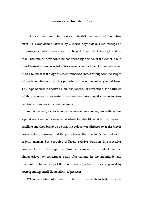
Laminar and Turbulent FlowObservation shows that two entirely different types of fluid flow exist. This was demon- strated by Osborne Reynolds in 1883 through an experiment in which water was discharged from a tank through a glass tube. The rate of flow could be controlled by a valve at the outlet, and a fine filament of dye injected at the entrance to the tube. At low velocities, it was found that the dye filament remained intact throughout the length of the tube, showing that the particles of water moved in parallel lines. This type of flow is known as laminar, viscous or streamline, the particles of fluid moving in an orderly manner and retaining the same relative positions in successive cross- sections.As the velocity in the tube was increased by opening the outlet valve, a point was eventually reached at which the dye filament at first began to oscillate and then broke up so that the colour was diffused over the whole cross-section, showing that the particles of fluid no longer moved in an orderly manner but occupied different relative position in successive cross-sections. This type of flow is known as turbulent and is characterized by continuous small fluctuations in the magnitude and direction of the velocity of the fluid particles, which are accompanied by corresponding small fluctuations of pressure.When the motion of a fluid particle in a stream is disturbed, its inertiawill tend to carry it on in the new direction, but the viscous forces due to the surrounding fluid will tend to make it conform to the motion of the rest of the stream. In viscous flow, the viscous shear stresses are sufficient to eliminate the effects of any deviation, but in turbulent flow they are inadequate. The criterion which determines whether flow will be viscous of turbulent is therefore the ratio of the inertial force to the viscous force acting on the particle. The ratioμρvl const force Viscous force Inertial ⨯= Thus, the criterion which determines whether flow is viscous or turbulent is the quantity ρvl /μ, known as the Reynolds number. It is a ratio of forces and, therefore, a pure number and may also be written as ul /v where is the kinematic viscosity (v=μ/ρ).Experiments carried out with a number of different fluids in straight pipes of different diameters have established that if the Reynolds number is calculated by making 1 equal to the pipe diameter and using the mean velocity v , then, below a critical value of ρvd /μ = 2000, flow will normally be laminar (viscous), any tendency to turbulence being damped out by viscous friction. This value of the Reynolds number applies only to flow in pipes, but critical values of the Reynolds number can be established for other types of flow, choosing a suitable characteristic length such as the chord of an aerofoil in place of the pipe diameter. For agiven fluid flowing in a pipe of a given diameter, there will be a critical velocity of flow corresponding to the critical value of the Reynolds number, below which flow will be viscous.In pipes, at values of the Reynolds number > 2000, flow will not necessarily be turbulent. Laminar flow has been maintained up to Re = 50,000, but conditions are unstable and any disturbance will cause reversion to normal turbulent flow. In straight pipes of constant diameter, flow can be assumed to be turbulent if the Reynolds number exceeds 4000.Pipe NetworksAn extension of compound pipes in parallel is a case frequently encountered in municipal distribution system, in which the pipes are interconnected so that the flow to a given outlet may come by several different paths. Indeed, it is frequently impossible to tell by inspection which way the flow travels. Nevertheless, the flow in any networks, however complicated, must satisfy the basic relations of continuity and energy as follows:1. The flow into any junction must equal the flow out of it.2. The flow in each pipe must satisfy the pipe-friction laws for flow in a single pipe.3. The algebraic sum of the head losses around any closed circuit must be zero.Pipe networks are generally too complicated to solve analytically, as was possible in the simpler cases of parallel pipes. A practical procedure is the method of successive approximations, introduced by Cross. It consists of the following elements, in order:1. By careful inspection assume the most reasonable distribution of flows that satisfies condition 1.2. Write condition 2 for each pipe in the formh L = KQ n(7.5) where K is a constant for each pipe. For example, the standard pipe-friction equation would yield K= 1/C2and n= 2 for constant f. Minor losses within any circuit may be included, but minor losses at the junction points are neglected.3. To investigate condition 3, compute the algebraic sum of the head losses around each elementary circuit. ∑h L= ∑KQ n. Consider losses from clockwise flows as positive, counterclockwise negative. Only by good luck will these add to zero on the first trial.4. Adjust the flow in each circuit by a correction, ΔQ , to balance the head in that circuit and give ∑KQ n = 0. The heart of this method lies in the determination of ΔQ . For any pipe we may writeQ = Q 0 +ΔQwhere Q is the correct discharge and Q 0 is the assumed discharge. Then, for a circuit100/Q h n h Q Kn Q K Q L L n n ∑∑∑∑∆-=-=- (7.6) It must be emphasized again that the numerator of Eq. (7.6) is to be summed algebraically, with due account of sign, while the denominator is summed arithmetically. The negative sign in Eq. (7.6) indicates that when there is an excess of head loss around a loop in the clockwise direction, the ΔQ must be subtracted from clockwise Q 0’s and added to counterclockwise ones. The reverse is true if there is a deficiency of head loss around a loop in the clockwise direction.5. After each circuit is given a first correction, the losses will still not balance because of the interaction of one circuit upon another (pipes which are common to two circuits receive two independent corrections, one for each circuit). The procedure is repeated, arriving at a second correction, and so on, until the corrections become negligible.Either form of Eq. (7.6) may be used to find ΔQ . As values of K appear in both numerator and denominator of the first form, values proportional to the actual K may be used to find the distribution. Thesecond form will be found most convenient for use with pipe-friction diagrams for water pipes.An attractive feature of the approximation method is that errors in computation have the same effect as errors in judgment and will eventually be corrected by the process.The pipe-networks problem lends itself well to solution by use of a digital computer. Programming takes time and care, but once set up, there is great flexibility and many man-hours of labor can be saved.The Future of Plastic Pipe at Higher PressuresParticipants in an AGA meeting panel on plastic pipe discussed the possibility of using polyethylene gas pipe at higher pressures. Topics included the design equation, including work being done by ISO on an updated version, and the evaluation of rapid crack propagation in a PE pipe resin. This is of critical importance because as pipe is used at higher pressure and in larger diameters, the possibility of RCP increases.Several years ago, AGA’s Plastic Pipe Design Equation Task Group reviewed the design equation to determine if higher operating pressurescould be used in plastic piping systems. Members felt the performance of our pipe resins was not truly reflected by the design equation. It was generally accepted that the long-term properties of modern resins far surpassed those of older resins. Major considerations were new equations being developed and selection of an appropriate design factor.Improved pipe performanceMany utilities monitored the performance of plastic pipe resins. Here are some of the long-term tests used and the kinds of performance change they have shown for typical gas pipe resins.Elevated temperature burst testThey used tests like the Elevated Temperature Burst Test, in which the long-term performance of the pipe is checked by measuring the time required for formation of brittle cracks in the pipe wall under high temperatures and pressures (often 80 degrees C and around 4 to 5-MPa hoop stress). At Consumers Gas we expected early resins to last at least 170 hrs. at 80 degrees C and a hoop stress of 3 MPa. Extrapolation showed that resins passing these limits should have a life expectancy of more than 50 yrs. Quality control testing on shipments of pipe made fromthese resins sometimes resulted in product rejection for failure to meet this criterion.At the same temperature, today’s resins last thousands of hours at hoop stresses of 4.6 MPa. Tests performed on pipe made from new resins have been terminated with no failure at times exceeding 5,700 hrs. These results were performed on samples that were squeezed off before testing. Such stresses were never applied in early testing. When extrapolated to operating conditions, this difference in test performance is equivalent to an increase in lifetime of hundreds (and in some cases even thousands) of years.Environmental stress crack resistance testSome companies also used the Environmental Stress Crack Resistance test which measured brittle crack formation in pipes but which used stress cracking agents to shorten test times.This test has also shown dramatic improvement in resistance brittle failure. For example, at my company a test time of more than 20 hrs. at 50 degrees C was required on our early resins. Today’s resins last well above 1,000 hrs. with no failure.Notch testsNotch tests, which are quickly run, measure brittle crack formation in notched pipe or molded coupon samples. This is important for the newer resins since some other tests to failure can take very long times. Notch test results show that while early resins lasted for test times ranging between 1,000 to 10,000 min., current resins usually last for longer than 200,000 min.All of our tests demonstrated the same thing. Newer resins are much more resistant to the growth of brittle crack than their predecessors. Since brittle failure is considered to be the ultimate failure mechanism in polyethylene pipes, we know that new materials will last much longer than the old. This is especially reassuring to the gas industry since many of these older resins have performed very well in the field for the past 25 yrs. with minimal detectable change in properties.While the tests showed greatly improved performance, the equation used to establish the pressure rating of the pipe is still identical to the original except for a change in 1978 to a single design factor for all class locations.To many it seemed that the methods used to pressure rate our pipe were now unduly conservative and that a new design equation was needed. At this time we became aware of a new equation being balloted atISO. The methodology being used seemed to be a more technically correct method of analyzing the data and offered a number of advantages.Thermal Expansion of Piping and Its CompensationA very relevant consideration requiring careful attention is the fact that with temperature of a length of pipe raised or lowered, there is a corresponding increase or decrease in its length and cross-sectional area because of the inherent coefficient of thermal expansion for the particular pipe material. The coefficient of expansion for carbon steel is 0.012 mm/m˚C and for copper 0.0168mm/m˚C. Respective module of elasticity are for steel E = 207×1.06kN/m2 and for copper E = 103×106 kN/m2. As an example, assuming a base temperature for water conducting piping at 0˚C, a steel pipe of any diameter if heated to 120˚C would experience a linear extension of 1.4 mm and a similarly if heated to copper pipe would extend by 2.016 mm for each meter of their respective lengths. The unit axial force in the steel pipe however would be 39% greater than for copper. The change in pipe diameter is of no practical consequence to linear extension but the axial forces created by expansion or contractionare con- siderable and capable of fracturing any fitments which may tend to impose a restraint;the magnitude of such forces is related to pipe size. As an example,in straight pipes of same length but different diameters, rigidly held at both ends and with temperature raised by say 100˚C, total magnitude of linear forces against fixed points would be near enough proportionate to the respective diameters.It is therefore essential that design of any piping layout makes adequate com- pensatory provision for such thermal influence by relieving the system of linear stresses which would be directly related to length of pipework between fixed points and the range of operational temperatures.Compensation for forces due to thermal expansion. The ideal pipework as far as expansion is concerned, is one where maximum free movement with the minimum of restraint is possible. Hence the simplest and most economical way to ensure com- pensation and relief of forces is to take advantage of changes in direction, or where this is not part of the layout and long straight runs are involved it may be feasible to introduce deliberate dog-leg offset changes in direction at suitable intervals.As an alternative,at calculated intervals in a straight pipe run specially designed expansion loops or “U” bends should be inserted. Depending upon design and space availability, expansion bends within a straight pipe run can feature the so called double offset “U” band or thehorseshoe type or “lyre” loop.The last named are seldom used for large heating networks; they can be supplied in manufacturers’ standard units but require elaborate constructional works for underground installation.Anchored thermal movement in underground piping would normally be absorbed by three basic types of expansion bends and these include the “U”bend, the “L”bend and the “Z”bend.In cases of 90 changes indirection the “L” and “Z”bends are used.Principles involved in the design of provision for expansion between anchor points are virtually the same for all three types of compensator. The offset “U” bend is usually made up from four 90° elbows and straight pipes; it permits good thermal displacement and imposes smaller anchor loads than the other type of loop. This shape of expansion bend is the standardised pattern for prefabricated pipe-in-pipe systems.All thermal compensators are installed to accommodate an equal amount of expansion or contraction; therefore to obtain full advantage of the length of thermal movement it is necessary to extend the unit during installation thus opening up the loop by an extent roughly equal the half the overall calculated thermal movement.This is done by “cold-pull” or other mechanical means. The total amount of extension between two fixed points has to be calculated on basis of ambient temperature prevailing and operational design temperatures so that distribution of stresses and reactions at lower and higher temperatures are controlledwithin permissible limits. Pre-stressing does not affect the fatigue life of piping therefore it does not feature in calculation of pipework stresses .There are numerous specialist publication dealing with design and stressing calculations for piping and especially for proprietary piping and expansion units; comprehensive experience back design data as well as charts and graphs may be obtained in manufacturers’publications, offering solutions for every kind of pipe stressing problem.As an alternative to above mentioned methods of compensation for thermal expansion and useable in places where space is restricted, is the more expensive bellows or telescopic type mechanical compensator. There are many proprietary types and models on the market and the following types of compensators are generally used.The bellows type expansion unit in form of an axial compensator provides for expansion movement in a pipe along its axis; motion in this bellows is due to tension or compression only.There are also articulated bellows units restrained which combine angular and lateral movement; they consist of double compensator units restrained by straps pinned over the center of each bellowsor double tied thus being restrained over its length.Such compensators are suitable for accommodating very pipeline expansion and also for combinations of angular and lateral movements.层流与紊流有两种完全不同的流体流动形式存在,这一点在1883年就由Osborne Reynolds 用试验演示证明。
给水排水专业英语翻译

《给水排水专业英语》Lesson 1specific yield [spə'sifik] [ji:ld] 单位产水量mass curve 累积曲线capital investment 投资recurring natural event ['nætʃərəl] 重现历史事件subterranean [sʌbtə'reiniən] 地下的groundwater 地下水surface water 地表水tap [tæp]开关、龙头;在…上开空(导出液体)swampland ['swɔmplænd] n. 沼泽地;沼泽地带capillary [kə'piləri] n. 毛细管adj. 毛状的,毛细管的hygro- [词头] 湿(气),液体hygroscopic [,haigrəu'skɔpik] adj. 易湿的,吸湿的hygroscopic moisture 吸湿水stratum ['streitəm] n. [地质学]地层,[生物学](组织的)层aquifer ['ækwəfə] ['ækwifə] n.含水层,地下蓄水层saturation [,sætʃə'reiʃən] n.饱和(状态),浸润,浸透,饱和度hydrostatic [,haidrəu'stætik] adj. 静水力学的, 流体静力学的hydrostatic pressure 静水压力water table 1. 地下水位,地下水面,潜水面2. 【建筑学】泻水台;承雨线脚;飞檐;马路边沟[亦作water-table]Phreatic surface [fri(:)'ætik]地下水(静止)水位,浅层地下水面Superficial [sju:pə'fiʃəl] adj. 表面的,表观的,浅薄的Porosity [pɔ:'rɔsiti] n. 多孔性,有孔性,孔隙率Unconfined ['ʌnkən'faind] adj. 无约束的,无限制的Permeability [,pə:miə'biliti] n. 弥漫, 渗透, 渗透性Permeameter [pə:mi'æmitə] n.渗透仪,渗透性试验仪)Clay [klei] n. 粘土,泥土gravel ['ɡrævəl]n.[总称]砾,沙砾,小石;砾石cone of depression [kəun] 下降漏斗, [水文学]下降锥体drawdown ['drɔ:daun] n. 水位下降(降落,消耗,减少)integrate ['intigreit] 【数学】作积分运算;求积分observation well [,əbzə:'veiʃən] 观测井,观测孔extraction [ik'strækʃən] n. 抽出,取出,提取(法),萃取(法)derivation [deri'veiʃən] n. 1. 导出,引(伸)出,来历,出处,得出,得到;诱导,推论,推理;溯源【数学】1) (定理的)求导,推导2) 微商,微分,导数【语言】词源,衍生deplete [di'pli:t] v. 耗尽, 使...衰竭refuse [ri'fju:z] n. 废物,垃圾vt. 拒绝,谢绝dump [dʌmp] n. 垃圾场,垃圾堆,堆存处vt. 倾卸,倾倒(垃圾)unconfined aquifer 潜水含水层,非承压含水层,无压含水层confined aquifer 自流含水层,承压含水层homogeneous [,hɔməu'dʒi:njəs] adj. 同类的,相似的,均匀的,均相的;同种类的,同性质的;相同特征的Aquaclude 不透水层,难渗透水的地层Offset ['ɔ:fset] n.偏移量抵销,弥补,分支,胶印,平版印刷,支管,乙字管Vt. 弥补,抵销,用平版印刷vi. 偏移,形成分支sophisticated [sə'fistikeitid] adj. 复杂的,需要专门技术的;诡辩的,久经世故的equilibrium [,i:kwi'libriəm] n. 平衡,均衡Water Supply(给水工程)A supply of water is critical to the survival of life, as we know it.(众所周知,水对生命的生存至关重要。
大学专业英语给排水专业课文翻译

第7章 水处理工艺选择 流域管理应该被视为给水系统运行的一部分,这对于保护原水水质非常重要。 在取水构筑物之后,是水的处理工艺。目前在市政水处理的预处理工艺有:筛选,预沉淀或 清淤,化学药剂添加和曝气。 筛选应用在地表水的预处理之中。预沉淀常常用于从河水去 除悬浮物质. 化学处理,在水厂内混凝之前,频繁用于提高预沉淀效果,处理难去除的物质, 如味道和气味的化合物、色度,降低高的细菌浓度。用于预沉淀的传统化学药剂是聚合电解 质和明矾。曝气习惯上是从地下水中除铁除锰的第一步,也是分离溶解性气体如硫化氢和二 氧化碳的标准的方法。用于水厂的处理工艺依赖原水水源和所需的出厂水水质。 选择用于 处理的具体化学药剂基于运行所需反应的有效性和成本。例如,活性炭、氯、二氧化氯和高 锰酸钾都可用于味道和气味的控制。虽然价格最低廉,但过量的氯化,会产生不期望出现的 三卤甲烷。在地表水处理厂中经常提供用于投加两到三种除味的化学药剂的设备,所以操作 者可以选择最有效和最经济的化学应用。没有用于各种水体的色度去除的固定方法。经过足 够预处理明矾混凝,采用化学氧化药剂或者活性炭,可能提供满意的去除。另一方面,更昂 贵的混凝剂有可能证明更加有效并降低整体化学药剂成本。也许在水处理工艺设计要考虑最 重要的是提供灵活性。操作者应该有一些手段来改变某些化学药剂的应用点(投加点)。例 如,加氯的投药管线常常提供满足前投加、中间投加、后投加氯的要求。应该提供多种药剂 进料器和存储容器,使处理工艺能采用不同的化学药剂。原水水质的降解,或者药剂成本的 改变,可能决定了在混凝中混凝剂和助凝剂使用药剂类型的改变。在地表水处理厂情况下, 预留场地以背建额外的预处理设施建设空间是值得考虑的。河水流量可能由于水坝的建设、 渠道的改进或者上游用水而改变。水质会因人为改变和流域的侵占而改变源于市政和工业废 物和农业地表径流的污染物浓度可能增加。湖泊会变得更加富营养化。通过增加曝气装置容 量、增加加氯量,使用沉淀池作为调节池,安装完毕后,水厂生产能力得到扩大,处理工艺 转变成只去除铁锰。目前该水厂只能够运行曝气氧化去除铁锰与氯化消毒。由于水井供水稳 定,全年的出厂水水质优良。图 2-3 的给水处理厂是一个始建于 1950 年代的传统的地表水 处理厂。从那时起,湖水水源日益富营养化,已经提供额外的设备进行味道与气味的控制。 在较差原水水质的关键时期,活性炭、二氧化氯和各种用于提高药品处理的辅助药剂目前是 适宜的。在一年之中的大部分时间,最终出水是非常可口的,但是在春秋季节的湖泊倒层期 间,味道和气味不能够被完全去除。对于水质剧烈变化的浑浊污染的河水而言,应该采用一 个复杂而灵活的处理系统。一般的处理方案包括:用于沉砂的普通沉淀,混合与沉淀,必要 的情况下采用混凝剂;分离处根据原水水质的变化,这个水厂的运行每天都会改变,每个季 节都会改变。即使这样,一些难处理的无机或有机物质仍然能够通过复杂的处理系统。 理以实现部分软化;在澄清池中的絮凝,双媒过滤,加氯获得余氯,pH 调节和结垢控制。 一个河水处理厂应该具有足够的工艺高度,以防止任何污染紧急事件短流的可能性。 第8章 混凝 显然,如果在水的混凝与软化过程中的化学反应将要发生的话,那么化学药剂必须与水进行 混合。在这一章节我们将要开始关注必要的物理方法以完成混凝与软化的过程。 下面将要提出的基本原理对于混合、絮凝以及过滤的操作都是适用的。或者,或者称为快速 混合,是由此化学药剂快速均匀的分布到水中的过程。理想状态下,化学药剂会迅速分散到 水中。在混凝和软化的过程中, 在快速混合中发生的化学反应形成了沉淀。在混凝过程中 形成氢氧化铝或氢氧化铁,而在软化过程中形成碳酸钙和氢氧化镁。在形成沉淀后,有必要 使它们互相碰触,以使得它们能够聚集,然后形成更大的颗粒,叫做絮体。这个接触的过程 叫做絮凝,它是通过缓慢、柔和的混合完成的。在给水处理与污水处理的过程中,混合的程
给排水工程外文翻译

给排水工程外文翻译 Final approval draft on November 22, 2020Short and Long Term Advantage roof drainage design performanceDecade has witnessed great changes in the design of the roof drainage system recently, particularly, siphon rainwater drainage system has been gradually improved, and there is likely to be the key application. At the same time these changes, urban drainage system design has undergone tremendous changes, because the scope of a wider urban drainage system design for sustainable development, as well as people for climate change flooding more attention. The main contents of this article is how to design roof drainage systems and make a good performance. Special attention is how to get rid of bad habits already formed the design, but also need to consider innovative roof drainage system, such as green roofs and rainwater harvesting systems.Practical application: In the past few years, the design of the roof rainwater drainage system has undergone tremendous changes. On large buildings, siphon rainwater drainage technology has been very common, as well as green roofs because it is conducive to green development, being more and more applications. Taking into account the ongoing research, this article focuses on how to effectively design a variety of roof rainwater drainage system, and make it achieve the desired design effect.1. IntroductionIn the past decade, the city and the water drainage system design has been widely accepted thinking about sustainable urban drainage system, or the optimal management direction. The main principles of the design of these systems is both a local level in line with the quality of development, but also to create some economic benefits for the investors. This principle has led to the development of new changes in the sump. Although the application of such a device is gradually reduced, but the urban environment relatively high demand areas still require 100% waterproof and rapid drainage, such as the roof. Typically roof drainage system in the design, construction and maintenance has not been given due attention. Although the drainage system investment costs account for only a small portion of the total construction investment, but not able to judge the loss caused by poor design.There are two different forms of roof drainage system design methods, namely the traditional and siphon method. Traditional systems rely on atmospheric pressure work, the drive ram affectedsink flow depth. Therefore, the conventional roof drainage systems require a relatively large diameter vertical drop tube, prior to discharge, all devices must be connected to the groundwatercollection pipe network. In contrast, siphonic roof drainage pipe systems are generally designed to full flow (turbulent flow meansthat require less exhaust pipe), which will form a negative pressure, the larger the higher flow rate and pressure head. Typically siphon system requires less down pipe work under negative pressure to the water distribution network can mean higher altitude work, thereby reducing the amount of underground pipe network.Both systems consists of three parts: the roof, rainwater collection pipes, pipe network.All of these elements are able to change the water pressure distribution system. This section focuses on the role and performance of each part. Due to the principle of siphon system has not been well understood, resulting argument is relatively small, this article will highlight siphon system.2. RoofThe roof is usually designed by the architect, designer and not by the drainage design. There are three main roof.2.1 Flat roofFlat roofs are used in industrial buildings less rainfall regions and countries. This roof is not completely flat, but lower than the minimum roof slope may require. For example, the United Kingdom require maximum slope of 10 °. Setting minimum slope in order to avoid any unnecessary water.Despite the flat roof if it is not properly maintained will have more problems, but it will reduce the dead zone within the building, and the ratio of sloping roofs in favor of indoor air.2.2 sloping roofsMost residential and commercial buildings are pitched roof, inclined roof is the biggest advantage can quickly drain, thereby reducing leakage. In temperate regions, we need to consider carrying roof snow load. Once it rains, rainfall through the sloping roofs can be determined by calculation. When rainfall data can be used, you can use the kinematic theory to solve such problems.2.3 green roof (flat or inclined)It can prove roof is the oldest green roofs, including rainfall can reduce or disperse roof planted with plants. It can be planted with trees and shrubs roof garden, it can also be a vegetated roof light carpet. Wherein the latter technique has been widely used. Some of these applications tend to focus on aesthetic requirements and are often used in green development. Since the aesthetic requirements and pressure requirements, as well as green roofs thermal insulation function, reduce the heat island effect, silencer effect, extend the life of the roof.Green roofs in Germany, the most widely used, followed in North America, but to consider the impact on the aesthetics. Germany is by far the most experienced countries in the 19th century have practical application, then as an alternative to reduce the risk of fire tarroof an option in urban areas. Germany is currently the main research question on the cultivation of other issues to consider smaller cities. A study from 1987 to 1989, was found packed with 70 mm thick green roof can be reduced by 60% -80% of heat loss. In a Canadianwork computer model based on the roof indicates that as long as the sump, the area can reach 70% of the roof area can be reduced by 60 percent in one year, the same model was also used for artificial rainfall, which the results indicate that rainfall in the catchment season helps to drain away rainwater.However, none of these studies show that green roofs can play a useful role in the rainfall season, or how high collection efficiency of water supply. The United States did some tests, as long as the green roofs regular watering, can reduce 65 percent of the runoff ina rainfall. America's most authoritative green roof guidelines by the New Jersey state environmental agencies promulgated. The mainprinciple is to solve the structural problems of light, and how can the normal drainage after two years.Rainfall period is based on the probability of failure is determined. The system is typically based on rainfall during rainstorms two minutes, two minutes, have a choice. Although this model will get more traffic, but there is no other better alternative. Studies have shown that the traditional model is applied to study green roofs are premature.Loss factor than traditional roof records should be small, about 98.7%.Peak flow will be reduced, although not penetrate, the surface roughness but also have a significant impact.Concentrated rainfall than two minutes for a long time,especially for large roof areas, such as public buildings, commercial buildings, industrial buildings.Urban drainage design should also consider other factors, for a complex system, a green roof in a rain is not enough. Water flow duration curve shows a longer than traditional systems. And two independent and will affect between is possible, which requires a more precise time period.3. Rainwater CollectorBasic requirements rainwater collector is designed to be able to accommodate rainfall rainstorms. Although it is possible to make a slightly inclined roof drainage purposes, but the nature of the construction industry and building settlement will become flat roofTypically, the tank is placed in a horizontal, sectional view of the water is outwardly inclined, which the role of hydrostatic.3.1 drain outletAnalyzing rainwater collector has sufficient volume is the key to the sump outlet external setting conditions. Also affect the flow rate into the storm water drainage system piping, but also affect the depth of the water catchment. Although the depth of the sump will not bring any particular problems, but too deep can cause excessive sump.Numerous studies in the 1980s showed that the flow of conventional roof drainage system outlet can be divided into two cases. It depends on the size of the depth and size of the outlet. When the water depth is less than half the diameter of the outlet, the flow of the first type, and the outlet of the flow can be calculated by an appropriate equation; water depth increases, exports are slowly clogging the flow will become another form forms, at the same time, the flow of exports can be obtained through other equations. While conventional roof drainage systems are designed to be free-draining, but may cause limitations encountered in the design of the flow is not free. In this case, it will require additional depth.Siphon roof drainage systems, the outlet is designed to be submerged stream. In this case, the depth of the outlet of the decision is more complicated, because the design of the sump depends on the flow. Recent studies have shown that conventional roof drainage systems use a variety of non-standard catchment, their depth and height, bigger than the diameter of the outlet. This will eventually result in a siphon effect. For a given catchment, the flow depends on the starting end of the drop tube diameter. A similar phenomenon has also been used to study the standard catchment, in these circumstances, only limited siphon action occurs within relatively close distance from the exit.3.2 tank flow classificationIn the complex flow sump outlet flow classification, can be seen from Table 2a, the flow will be uniform layering, regardless of whether the same inlet flow. Table 2b and 2c show, exportdistribution will greatly influence the flow.When the outlet is not a free jet, sump outlet complex flow classification is difficult to describe. Because each catchment tank pressures are likely to be merged. For example, the siphon tube system design point is at near full jet outlet flow classification depends on the energy loss of each branch.3.3 hydrostatic sectionalSump shape of the water surface in the canal can be classified according to the flow equation. In most cases, a low flow rate meansthat there is less friction loss, if exports are free jet, thefriction loss is negligible cross-section through the hydrostatic equation 1 to determine the horizontal distance.Where Q-- flow (m3 / s)T- surface width (m)g- acceleration of gravity (m / s2)F- flow area (m2)Equation 1 can not be ignored when the friction required to correct (or very long pipe velocity is large), or not a free jet.3.4 The current design methodsThe previous discussion has highlighted the main factors that should be considered with sink design. However, without the help of a certain number of models, computing hydrostatic sectional roof drainage system, the volume of the sump is possible. This large commercial and manufacturing industry, is a development opportunity, you can merge several kilometers of water routes. Thus, the conventional drainage system sump design methods are mainly based on experience, and assume that exports are free jet.Sump location in the building, it may cause the example to fail. Different interface sumpExcept in the case cited above, but also allows designers to use empirical data.3.5 Digital ModelLarge number of digital models can be used to accurately describe the flow of any form of catchment tank, regardless of whether the roof flows stable. An example of this model is a combination of roof space model. This model enables users to classify different aspects of the data indicated, includes: details of the rains, the roof surface drainage and other details. Kinematics have also been used to study rainwater tank to flow from the research collection. A typical method is based on open system to solve a basic problem of spatial mobility. This model automatically resolve the sump outlet flow situation, but also to deal with the case of free jet can also be simulated space limited mobility and submerged discharge. Output values include depth and flow rate.Currently, the model is essentially just a variety of research tools, but also through practical engineering test. However, we should face up to the various role models.4 pipe systems groupComposition in the form and scope of the tube group determinesthe roof drainage system relies mainly on the traditional system or siphon action.4.1 Traditional stormwater systemsConventional roof drainage systems, the ground plane is generally vertical pipe-line network, connected to the sump outlet and underground drainage systems, critical systems as well as compensating tube. It should be emphasized that the angle between the ground and the compensating tube is less than 10 °. Capacity of the entire system relies mainly on the outlet tube instead of down.Flow vertical tube is usually free-flowing, full of only 33%, the efficiency depends on the excess length of the tube. If the drop tube long enough (typically greater than 5m), there may be an annular flow. Similarly, under normal circumstances flow compensation pipe is free-flowing, full of up to 70%. Such designed process both for the design, various equations can also be used.4.2 Siphon roof drainage systemIn contrast with the traditional drainage systems, Siphon roof drainage system relies on air flow outside the system, and the tubeis full pipe flow stream.The designs are usually made on the assumption that the design of heavy rain, the system can quickly siphon discharge rainwater. This assumption allows the application of hydrostatic siphon system theory. Often used steady flow energy equation. While this approach ignores the small amount of energy loss at the entrance, but after the experiment showed that there are still conducive to practical use.However, steady-state design methods in the siphon system is exposed to rain when the system does not meet the standard requirements or changes in rainfall intensity is large is not applied. In the first case, there will be some mixing of air quality, annular flow occurs. These problems are not integrated in the system when more serious. Because usually designed rains are common, it is clear now design methodology over time may not apply to siphon system. This is a major disadvantage, because the design of the main problem isthe noise and vibration problems.Despite the disadvantages of the prior design approach, but a lot of the world's very few engineering failure reports. When a failure occurs, most likely for the following reasons:An incorrect understanding of the operation pointsSubstandard materials listInstallation defectsMaintenance mismanagementTo overcome these disadvantages, we have recently launched aseries of research projects, to discuss the siphon system, and the development of digital models. From this work we learn a lot.In contrast with conventional design methods of some assumptions, siphon system mainly has the following aspects:1) non-flow system of full flow2) levels of certain pipe-flowing full pipe flow3) full pipe flow downstream propagation through a vertical pipe, riser, etc.4) the inner tube flow occurs over the vertical section, the system to reduce the pressure5) downward tube is full pipe flow, there will be air lock6) appears completely siphon action until well into the air system is lower than a certain levelTable 4a column data indicate that below the design point, the system will siphon unstable flow, depth of the water collecting tank is insufficient to maintain the siphon action. Table 4b show that the unsteady flow in siphon system when it will appear.Table 5 lists the data output of a digital model. It can be seen that the model can accurately describe the siphon action, siphon and steady state, the data also show that the model can accurately describe the complex siphon action.5 ConclusionThis article has illustrated the critical roof drainage systems, but these are often overlooked in the urban drainage system design. This article also shows that the design process is a complex process, rely mainly on the performance of exports. The following conclusions are based on the design summed up:1) Run depend on three interacting parts: the roof, sump, water pipes2) Green roofs can reduce traffic and beautify the city3) the export performance of the system is essential4) siphon drainage system have a greater advantage in large-scale projects, but must be considered high maintenance costs5) Design siphon drainage system should consider additional capacity and operational issuesAlthough the green roof is a more attractive option, but the traditional roof of a building in the country will continue to dominate. Green roofs will be gradually developed, and gradually been widely accepted. Similarly, the roof drainage system shown effective that it will continue to play a huge role in the commercial building drainage systems.Roof drainage system of the greatest threats from climate change, existing systems tend to be not simply aging; rainfall patterns of change will result in inefficient operation, self-cleaning rate will be reduced. Changes in wind speed and the roof will also accelerate the aging of the roof, it is necessary to carry out maintenance. Taking into account the climate change, the increase in materials, roof collected rainwater will be more extensive. Currently, the amount of rain around the globe per person per day 7-300 liters in the UK, with an average consumption of 145L / h / d, of which onlyabout one liter is used by people, about 30 per cent of the toilet, study shows If water shortage, rainwater collected on the roof of developed and developing countries are recommended approach.屋顶排水设计性能的近期与远期优势最近十年见证了屋顶排水系统设计方面的巨大变化,特别的是,虹吸雨水排水系统已经得到逐步改善,并且有可能得到重点应用。
蓝梅主编 给排水科学与工程专业英语部分课文翻译中文版
第四单元给水系统一般来说,供水系统可划分为四个主要组成部分:(1)水源和取水工程(2)水处理和存储(3)输水干管和配水管网。
常见的未处理的水或者说是原水的来源是像河流、湖泊、泉水、人造水库之类的地表水源以及像岩洞和水井之类的地下水源。
修建取水构筑物和泵站是为了从这些水源中取水。
原水通过输水干管输送到自来水厂进行处理并且处理后的出水储存到清水池。
处理的程度取决于原水的水质和出水水质要求。
有时候,地下水的水质是如此的好以至于在供给给用户之前只需消毒即可。
由于自来水厂一般是根据平均日需求流量设计的,所以,清水池为水需求日变化量提供了一个缓冲区。
水通过输水干管长距离输送。
如果输水干管中的水流是通过泵所产生的压力水头维持的,那么我们称这个干管为增压管。
另外,如果输水干管中的水流是靠由于高差产生的可获得的重力势能维持的,那么我们称这个干管为重力管。
在输水干管中没有中间取水。
与输水干管类似,在配水管网中水流的维持要么靠泵增压,要么靠重力势能。
一般来说,在平坦地区,大的配水管网中的水压是靠泵提供的,然而,在不平坦的地区,配水管网中的压力水头是靠重力势能维持的。
一个配水管网通过引入管连接配水给用户。
这样的配水管网可能有不同的形状,并且这些形状取决于这个地区的布局。
一般地,配水管网有环状或枝状的管道结构,但是,根据当地城市道路和街区总体布局计划,有时候环状和枝状结构合用。
城市配水管网大多上是环状形式,然而,乡村地区的管网是枝状形式。
由于供水服务可靠性要求高,环状管网优于枝状管网。
配水管网的成本取决于对管网的几何形状合适的选择。
城市计划采用的街道布局的选择对提供一个最小成本的供水系统来说是重要的。
环状管网最常见的两个供水结构是方格状、环状和辐射状;然而,我们不可能找到一个最佳的几何形状而使得成本最低。
一般地,城镇供水系统是单入口环状管系统。
如上所说,环状系统有一些通过系统相互连接的管道使得通过这些连接接的管道,可以供水到同一个需水点。
给排水专业英语课文翻译

There are several species of bacteria that are widely found in the aquatic environment but so not normally cause illness in the immuno-competent. They are not therefore particularly associated with health problems from drinking-water. It is important to be aware of them nevertheless, as they have occasionally been associated with disease where people may already be ill with other conditions or their immune system is reduced and unable to cope (Dufour 1990).They are usually known as environmental bacteria, but I have also come across the terms adventitious or heterotrophic in this context (although heterotrophic strictly means they get their source of energy and cellular carbon from the oxidation of organic material, that is, by feeding on plants or animals-rather than photosvnchesis). Where laboratories carry out plare counts, it is often these bacteria that are cultured. There will be many different types of environmental bacturia but the imporiant ones for drinking-water safety are listed here.AeromonasAeromonas are commonly found in both fresh and salt waters. There are several species, each one favouring a particular environmental niche. Aeromonas bydropbila is found mainly in clean river water, Aeromonas sobria in stagnant water and Aeromonas caviae in marine water. They are so common that people have tried to use them in rivers as indicators of pollution. They are known to cause diarrhoea and infection in soft tissue where damaged skin comes into contact with contaminated river or lake water.Aeromonas caviae is the one most commonly associated with diarrhoea. Diarrhoeal infection is usually mild, although more severe symptoms have occasionally been known, including bloody diarrhoea and chronic colitis (inflammation of the colon).Aeromonas have been found in treated chlorinated water and sometimes, there is re-growth in the distribution pipes. Chlorine only appears to have a temporary effect on them and this may mean that it stops them from reproducing but does not kill them. If left (presumably so they can get their breath back and have a bit of a rest after the chlorine attack) they can continue as normal.有一些种类的细菌在水生环境中被发现,但通常不引起疾病immuno-competent。
给排水专业英语_中文1
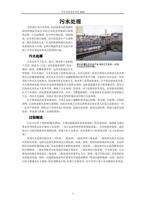
污水处理自然或生活污水处理,是指清除包括家庭排放的和地面径流在内的污水废水和地面污染物的过程。
它包括物理,化学和生物过程,消除物理,化学和生物污染物。
其目的是集中产生废物流(或经处理的污水)以及固体废物或污泥进行处理或再进入环境。
这种污物通常是在无意中受到了许多有毒的有机和无机物的污染。
污水起源污水是由个人住宅,机关,商业和工业机构产生的。
原进水(污水)包括家庭的厕所,浴室,淋浴,厨房,水槽废液等等,这些水将通过污水管排放。
在许多地区,污水也包括工业和商业污水。
在发达国家,家居分别将污水排放为灰水和黑水已经越来越普遍,因为灰水可以用于浇灌植物或回收用来冲马桶。
大量的污水还包括一些屋顶流下的水以及地表水。
因此城市废水包括住宅,商业和工业排放的废水,且可能包括雨水径流。
具有处理雨水能力的污水处理系统被称为合流排水系统。
这种系统通常是不被普遍采用,因为它们复杂化而且由于其季节性,降低了污水处理厂的效率。
由于流量的经常变化,也导致处理量往往大于必需的,因而使处理设施更昂贵。
此外,当遭遇暴雨时,过量的雨水会造成污水处理能力不足,因而引发溢流。
因此在设计排水管网时最好采用雨污分流系统。
由于降雨流经屋顶和地面时,会带走包括土壤颗粒和其他沉积物,重金属,有机物,动物排泄物,污油和油脂等各种污染物质。
因此有些地方会有法律要求在雨水排入河道之前要进行一些一定水平的处理。
例如以下对雨水进行的处理:盆地沉淀处理,湿地过滤处理,混凝土地窖过滤处理,和旋涡分离器(去除粗固体)。
过程概述污水可以在下列构筑物(化粪池,生物过滤器或好氧处理系统)附近被处理,或收集并通过排水管网和泵站送至城市污水处理厂(见污水处理和管道和基础设施)。
污水收集和处理,通常取决于当地州和联邦法规和标准。
来源于的工业废水,往往需要专门的处理过程(见工业废水处理)。
常规污水处理可能涉及三个阶段,一级处理,二级处理和三级处理。
一级处理包括在沉淀池中的短时停留,这样比较重的固体就会沉到池底,而油,油脂,更轻的固体则浮到水面。
- 1、下载文档前请自行甄别文档内容的完整性,平台不提供额外的编辑、内容补充、找答案等附加服务。
- 2、"仅部分预览"的文档,不可在线预览部分如存在完整性等问题,可反馈申请退款(可完整预览的文档不适用该条件!)。
- 3、如文档侵犯您的权益,请联系客服反馈,我们会尽快为您处理(人工客服工作时间:9:00-18:30)。
第四单元给水系统一般来说,供水系统可划分为四个主要组成部分:(1)水源和取水工程(2)水处理和存储(3)输水干管和配水管网。
常见的未处理的水或者说是原水的来源是像河流、湖泊、泉水、人造水库之类的地表水源以及像岩洞和水井之类的地下水源。
修建取水构筑物和泵站是为了从这些水源中取水。
原水通过输水干管输送到自来水厂进行处理并且处理后的出水储存到清水池。
处理的程度取决于原水的水质和出水水质要求。
有时候,地下水的水质是如此的好以至于在供给给用户之前只需消毒即可。
由于自来水厂一般是根据平均日需求流量设计的,所以,清水池为水需求日变化量提供了一个缓冲区。
水通过输水干管长距离输送。
如果输水干管中的水流是通过泵所产生的压力水头维持的,那么我们称这个干管为增压管。
另外,如果输水干管中的水流是靠由于高差产生的可获得的重力势能维持的,那么我们称这个干管为重力管。
在输水干管中没有中间取水。
与输水干管类似,在配水管网中水流的维持要么靠泵增压,要么靠重力势能。
一般来说,在平坦地区,大的配水管网中的水压是靠泵提供的,然而,在不平坦的地区,配水管网中的压力水头是靠重力势能维持的。
一个配水管网通过引入管连接配水给用户。
这样的配水管网可能有不同的形状,并且这些形状取决于这个地区的布局。
一般地,配水管网有环状或枝状的管道结构,但是,根据当地城市道路和街区总体布局计划,有时候环状和枝状结构合用。
城市配水管网大多上是环状形式,然而,乡村地区的管网是枝状形式。
由于供水服务可靠性要求高,环状管网优于枝状管网。
配水管网的成本取决于对管网的几何形状合适的选择。
城市计划采用的街道布局的选择对提供一个最小成本的供水系统来说是重要的。
环状管网最常见的两个供水结构是方格状、环状和辐射状;然而,我们不可能找到一个最佳的几何形状而使得成本最低。
一般地,城镇供水系统是单入口环状管系统。
如上所说,环状系统有一些通过系统相互连接的管道使得通过这些连接接的管道,可以供水到同一个需水点。
与枝状系统不同,在环状系统中,由于需水量在空间和时间上的变化,管道中的水流方向并非不变。
环状管网可为系统提供余量,提高系统应对局部变化的能力,并且保证管道故障时为用户供水。
从水质方面来说,环状形状可减少水龄,因此被推广。
管道的尺寸和配水系统的设计对减少水龄来说是重要的因素。
由于多方向水流模式和系统中流动模式随时间的变化,水不会停留在一个地方,这样减少了水龄。
环状配水系统的优缺点如表4.1所述。
优点:1.Minimize loss of services.as main breaks can be isolated due to multidirectional flow to demand points.2.Reliability for fire protection is higher due to redundancy in the system.3.Likely to meet increase in water demand -higher capacity and lower velocities.4.Better residual chlorine due to in line mixing and fewer dead ends.5.Reduced water age.在文献中曾记载过,只考虑最低成本设计的环状管网系统会转化成树状似的结构,这一做法导致在最终的设计中失去最初的几何形状。
环状保证了系统的可靠性。
因此,一个只考虑最低成本为依据的设计打败了在环状管网中所提供的基本功能。
有文献记载设计环状管网系统的方法。
尽管这个方法也是仅以考虑最低成本为基础,它通过对管网中所有管道最优化规划从而保持了管网的环状结构。
第五单元废水的收集和污水系统的设计污水可以划分为以下几个组成部分:生活污水: 从居民,商业点(比如银行、餐馆、零售商店)和公共设施(比如学校和医院)排放出来的污水。
工业废水:从工厂(比如制造业和化工过程)排放出来的废水。
渗入水和流入水:从地下水渗透到污水管系统的水,从屋顶的排水管、地面的排水管和管网的检查井流入的雨水。
雨水:由降水和雪水的产生量随季节变化,并且每周内的每一天,每天中的每个小时用水量和污水的产生量都不同。
在小的社区中,水的耗用和污水产生量的波动变化大于大的社区,且短时间内大于长时间。
由于收集和处理系统并没有以运输和处理这些工业废水中的废物为目的而设计,所以工业废水可能会对市政系统造成严重的危害。
工业废水中的废物会损坏污水管并且干扰污水处理厂的运作。
工业废水中的废物可能会通过污水处理厂但未被处理而直接排放,或者浓缩在污泥里,成为危险的废物。
最近,城市水资源的消耗和退化已经促使提倡建立一个可持续的城市水系统,这个系统提倡少用水、保护自然排水系统,通过节约用水和回用水减少废水排放的频率,严格控制水污染以及保护或者增强受纳水体生态系统。
城镇污水处理系统的基本元素如图5.1(a)和图5.1(b)所示。
三个主要的水污染控制组成部分是:城市排水系统(既运送地表径流又运送生活污水),污水处理厂和受纳水体。
这三个水污染控制组成部分间的相互依赖和连通性如图表中暗示靠重力或增压方式进行水力输送的箭头所示。
像从这三个水污染控制组成部分中通过机械移除固体和污泥的其他水力输送模式已经被省略。
城市的排水系统用来防止内涝,减少由于地面汇集成水塘带来的不便,减少了对人类健康的危害,改善了美感。
在上个世纪,城市的排水系统已经发展成两种模式,即,图5.1(a)所示的分流制排水系统和图5.1(b)所示的合流制排水系统。
合流制排水系统在同一根管道中输送地表径流和生活污水。
在旱季,水被输送到污水处理厂并进行处理。
在雨季,随着流入合流污水管的径流量增加,水的收集系统和污水处理厂的容量满足不了暴增的排水量,过量的水流允许以所谓的合流溢流的形式脱离水的收集系统排放到受纳水体中。
在分流制排水系统中,地表径流通过雨水管输送和排放到受纳水体中,生活污水通过污水管输送到污水处理厂并且在排入受纳水体之前进行处理。
这两个排水系统存在许多变化。
图5.1(a)和图5.1(b)显示了在集水区排水、排水管、污水处理厂和受纳水体之间的相互联系。
雨水管排水和受纳水体之间的相互联系十分强烈并且与关于水循环的城镇化影响有关。
在城镇化的发展进程中,城市地表被屋顶、街道、人行道、停车场以及因土地利用活动变的密实的土壤等诸如此类的隔水元素覆盖。
因此,植物冠层对降水量的吸收作用变弱和渗入到地下的水量减少,与此同时,更多的雨水直接转换成地表径流。
不透水的地表径流快速汇集以及像排水沟、雨水管和排水管的典型水力促进导致了供水发生率和规模的增加。
这种影响在城镇地区因变直、变深和变线状分布的溪流而今进一步加剧。
如图5.1(b)所示,尽管在分流制系统中雨水和污水是分开输送排放的,但在二者之间不可避免地有一些连通。
城市污水流入到雨水管中导致了雨水被污染,雨水流入到污水管中增加了水流量从而导致水流量超过污水处理厂的容量使得污水溢流。
这样的流入来源包括污水管与雨水管的连通。
在污水管和雨水管以及地下水之间同样有一些连通,即,以地下水渗透(增加了水的流量)和管道渗出导致雨水污染的这种形式连通。
在一个设计和维护良好的分流制排水系统中,雨水管和污水管之间的连通不存在的,采用不漏水的污水管以防渗透,进而使在雨水和污水处理厂之间的相互作用最小化。
主要的剩余相互作用是那些在雨水或污水处理厂出水排放与受纳水体之间的相互作用。
雨天水流对污水处理厂产生水力和污染的冲击负荷,尽管这些冲击负荷不影响合理设计的设备的机械处理部分,但的确影响生化处理的工艺,尤其是硝化作用和反硝化作用,比如通过缩短反应时间,减少回流污泥量,以及当污泥流入终沉池时减少生物量等方式产生影响。
这些因素都可以导致降低处理效果和增加排放到受纳水体的污染物量。
在合流制排水系统中(图5.1a所示),这三个主要的水污染控制部分之间的相互作用强于分流制系统中它们之间的相互作用。
在晴天时,合流制排水系统的功能像只产生一种水流的分流制排水系统的功能,这种水流是输送到污水处理厂去处理的生活污水。
在雨天,地表径流直接进入合流管。
当合流管道系统的容量已经无法满足排水量,过量的合流水或带着负面影响,直接排放入受纳水体(即合流制溢流污水),或者进入污水处理厂联动的溢流设施。
与雨水污染的特点类似,合流制溢流污水的污染特点受到生活污水和从合流污水管中冲刷出来的污泥强烈地影响。
因此,合流制溢流污水是固体、可生物降解有机物、营养盐和排泄物细菌的十分重要来源。
合流制溢流污水对受纳水体的影响和前面部分叙述的类似,但是就氧消耗和水体富营养化和增长的生产力以及排泄污染物来说,合流制溢流污水对水体的影响更大。
因此,在溢流污水排入受纳水体之前对其控制是值得做的。
像这样的控制设备应该与污水处理厂联动运作。
第八单元凝聚和絮凝在水中有三种物质存在形式。
这些物质是以溶解形式存在的化学物质,胶体粒子和悬浮粒子。
凝聚或絮凝将会去除胶体和悬浮颗粒。
在水处理工业中,凝聚和絮凝这两个术语暗示不同的机理。
尽管凝结和絮凝经常混用,但是它们指的是两个不同的工艺。
凝聚是指使胶体颗粒和非常细小的固体悬浮物脱稳并在条件适合时脱稳颗粒开始聚集的处理工艺。
絮凝是指脱稳的胶体颗粒进一步聚结成更大的聚集体以至于它们可以从污水中分离出来。
凝聚凝聚是由于添加了化学试剂(助凝剂)从而使胶体粒子脱稳。
脱稳的目的是减少胶体粒子之间的排斥力而使其能够结合更多的胶体粒子,使它们在随后的沉淀过程中得以去除。
原水中导致色度和浊度的粒子主要是黏土、淤泥、病毒、细菌、腐殖酸、矿物质(包括石棉、硅酸盐、二氧化硅和放射性粒子)和有机粒子。
pH值大于4的水中,这样的粒子和分子往往带负电荷。
凝聚是用来去除以悬浮或胶体状态存在的废弃物。
胶体是以在0.1-1nm 范围的粒子形式存在。
这些粒子通过静置不会沉淀下来,并且以传统的物理处理工艺难以去除。
胶体颗粒在污水中既可以以亲水形式又可以以憎水形式存在。
憎水的胶体颗粒对液体介质没有亲和力并且在电解质存在的情况下缺乏稳定性。
憎水的胶体粒子易受这些因素影响从而凝聚。
亲水性的胶体粒子,比如蛋白质,对水有显著的亲和力。
与水亲和阻碍了絮凝并且常常需要特殊处理来达到有效的凝聚。
胶体的电性质产生了排斥力从而阻止了凝聚和沉降。
稳定化的离子被牢牢的吸附在提供负电荷粒子的内层,这些负电荷随着吸附的离子的数目和化合价变化而变化。
带相反电荷的离子形成外部扩散层,这个扩散层因静电力靠近胶体表面。
胶体的稳定性是由于静电斥力,而对于溶液中的亲水性胶体,水膜阻止了混凝。
凝聚的优势在于它可以缩短悬浮物沉降时间,并且对去除难以去除的细小颗粒行之有效。
混凝也可以有效地去除许多原生动物、细菌和病毒。