纠偏BF-3000说明书
纠偏说明书

K50纠偏控制系统(请务必在使用之前阅读)为了安全使用本产品▲在安装和使用之前,请务必详细阅读本说 明书,一定要注意安全,正确使用本产品, 并遵守本说明书中的各种规定。
▲本纠偏控制器是采用CPU 控制的机电设备, 用来纠正卷材的偏移,所以要严格遵守机电 设备有关规定和法则,适用标准,进行搬运、安装操作和维护。
在打开控制器准备安装和接线之前要断开控制器电源至少要5分钟。
正确的配置和安装是控制器正常运行的前提。
对以下几点要特别注意:● 安装工作必须在无电状态下进行。
●容许保护等级:保护接地,只有正确连接保护接地,才能减少外界电磁干扰。
●与电网断开后,要等电容放电完毕,才可进行操作。
●不要让任何异物进入控制器内。
●在使用前,要除去所有覆盖物,以防止控制器过热。
●切勿在易燃易爆等危险环境中使用。
●请勿将本产品安装在高温、潮湿等恶劣环境下。
● 请勿将产品直接安装在易受震动冲击的环境中。
● 任何单位部门(Kortis 和Kortis 指定公司除外)未经允许不得擅自拆卸、修理及更改产品。
※注意:Kortis对由于不遵守本说明或适用规则而造成的损坏概不负责。
※注意:因产品更新换代迅速,说明书有变动之处,恕不另行通知,本公司对此保留最终解释权。
危险如果错误操作,将会产生危险情况,导致伤亡。
注意如果错误操作,将会产生危险情况,造成设备损坏及财产损失。
设计注意事项目 录1.1 概述1.2 功能及特点1.3 操作界面第一章 系统概述112第二章 安装与配线2.1 控制器安装2.2 超声波传感器安装2.3 控制器基本配线34第三章 编程方法3.1 控制器菜单画面3.2 编程方法3.3 画面说明及参数设置678第四章 调试运行4.1 调试步骤4.2 控制器内部菜单4.3 调试方法99155.1 技术参数5.2 环境规格5.3 外形尺寸161617第五章 规格及维护5.4 系统维护1951.1 概述K50纠偏控制系统广泛应用于印刷、包装、造纸、纺织、机械等行业中,需要卷取纠偏、放卷纠偏或中间导向纠偏的场合。
光电纠偏控制器使用说明书接线及输入输出端口说明1#为对边对

光电纠偏控制器使用说明书一、接线及输入输出端口说明1#为对边对线光电头输出插口,即可作对边检测口作用,又可作对线检测口作用,三芯航空插接口。
可配一般光电头如Z3N-TB22使用。
2#为对线光电头输入插口,可作对线检测口作用,三芯航空插接口。
可配一般光电检测器使用。
3#为四芯光电检测器(如ZPS-2系列槽形双路光电头)输出插口,既可作对边检测口作用,又可作对线检测口作用。
7和8为左限位开关输入端口,接左限位开关常开触头。
9和10为右限位开关输出端口,接右限位开关常开触头。
交流同步电机的红色、黄色、白色和蓝色四线对应接入6、5、4、3四个接线端子。
(调换红色与蓝色接线可改变电机旋转方向。
)220V电源接入1、2两接线端子。
二、运行前的准备工作1、接线:按接线图要求将电源,电机,限位开关,光电头对应接好。
2、电机方向极性确定:(如按手动键,使控制器处于手动状态,再按极性正键),则按键,电机正方向旋转,材料活动架往左移动,按键,电机反方向旋转,材料活动架往右移动,如电机旋转方向与实际相反,可将电机红蓝两线调换接线.3、限位开关控制电机停止方向确定:(如按手动键,使控制器处于手动状态,再按极性正键), 则按键,电机正方向旋转,后碰触活动架移动方向的限位开关,电机运转停止,则表示限位有效,反之则碰触一端限位开关,电机应运转停止,则表示限位开关接线相反,必须给予调换.注意:检验限位开关时必须在电机运转的有效行程内,必须在手动档检验,否则一但限位失灵将损坏电机丝杆的机械结构。
4、材料对边或对线选择:对于材料首先确定它的基准位置是材料边缘还是印刷线条。
确定跟踪边缘以后,再确定左边缘还是右边缘,以后再决定电机方向极性。
对于印刷品的线条一般定于2MM以上线条作为对边处理。
反之则作为对线处理。
5、光电头的定位、调整:按自动键、对边对线键,确定是跟踪材料边缘或印刷线条后,将光斑对准材料边缘或印刷线条,调整光电头位置观察光电头上的指示灯,指示灯从亮-暗-亮,则表示设定成功,若无该状态,则无基准工作。
起重机同步纠偏仪说明书
龙门吊行车起重机行走啃轨问题和纠偏控制方案针对轨道龙门吊大车的刚性支腿与柔性支腿力矩不平衡,导致行走大车走偏而引起啃轨的问题,运用1种新型的力矩偏差调节与位置偏差调节相结合的P ID实时纠偏控制系统进行纠偏. 经实验,与其他控制系统相比,该系统具有一定的优越性,在实际应用中取得良好效果.Because of the torque imbalance between rigid leg and flexible leg of the railmounted gantry crane, the crane walks deflected and the p roblem of rail2gnawing is brought out. A new P IDreal2timecontrol system which rectifies the deviation combining torque modulation with position feedback isap2p lied. The experiment shows that it hasmore advantages compared with other control systems. It makesgood p rogress in the p ractical app lication.轨道式龙门吊与其他类型的港口机械相比,具有堆场利用率与作业效率高、结构简单、维护方便、运行成本低等一系列优点. 港口集装箱堆场作业的使用工况决定该机型跨度较大(通常为30 ~80m) ,沿轨道方向运行距离较长. 为满足作业效率的要求,大车运行机构的运行速度需达到90 m /min以上. 用户在感受其优点的同时,也经常会碰到1个共性问题,即大车运行啃轨.本文具体分析振华港机使用的轨道龙门吊在行走过程中出现的大车啃轨问题,并针对由大车的2个支腿力矩不平衡而引起的啃轨,采取1种新型的PLC结合BEN编码器和变频器来实现的实时PID纠偏控制.本文有2大特点:一是新的纠偏控制对象. 解决起重机啃轨问题的文章很多,但是很少有针对港口用的轨道龙门吊的;二是新型的控制方法. 传统的控制方法都是利用变频器调速,而本文利用频器调力矩,并结合PLC调位置,在实验中取得理想效果.1啃轨的危害啃轨又称“啃道”、“咬道”,指在龙门吊大车的运行过程中,车轮轮缘与轨道侧面接触,产生水平侧向推力所引起的轮缘与轨道的摩擦及磨损. 啃轨是轨道龙门吊运行中的主要问题,尤其在要求快速运行的场合,啃轨给龙门吊正常工作带来许多负面影响,形成事故隐患. 其主要危害有以下几点:(1)降低车轮和轨道的使用寿命. 啃轨造成车轮和轨道强制性接触,加剧2者的相互磨损,严重时可导致轮缘与轨道侧面的金属剥落及轮缘向外翘曲变形,从而加速车轮与轨道的损坏,降低使用寿命.(2)磨损轨道. 车轮啃轨加大轨道的磨损,严重者会将轨道磨出台阶,直至更换轨道.(3)增加运行阻力. 根据实际测定,龙门吊啃轨运行的阻力是正常阻力的2. 5~4. 5倍. 运行阻力的增加,迫使运行电动机和传动机构长期超载运行,可能造成烧坏电动机或扭断传动轴的后果.(4)龙门吊工作时噪声大、振动大. 由于大车车轮啃轨,必然产生水平侧向力,这种侧向力导致轨道横向位移,使固定轨道的螺栓松动,压板脱落,致使轨道向内或向外弯曲加大,加重啃轨,造成整台车在运行时产生巨大震动.(5)龙门吊在行驶中突然脱轨,可能会造成重大的设备、人身伤亡事故.2啃轨原因分析正常运行情况下,轨道龙门吊的车轮轮缘不与轨道侧面接触,车轮轮缘和轨道之间有一定的间隙,一般设计最大间隙为30~40 mm. 但由于某些原因(如机械制造中的偏差或运行中的一些因素) ,使运行中的车轮与轨道的接触面不在踏面中间(即车轮踏面的中心线与轨道的中心线不重合) ,造成车体偏斜,使整个起重机靠着轨道一侧接触而行走,从而产生啃轨. 啃轨的原因有许多,本文主要从以下几个方面作重点分析: (1)大车两侧驱动电动机不同步.由于运行阻力不等,会出现轨道龙门吊大车两侧的电机转速不等,导致左右车轮线速度不同,形成位置差,造成大车跑偏啃轨. 同时,由于轨道龙门吊行走大车的刚性支腿与柔性支腿的驱动力矩不平衡而引起速度和力矩偏差,也会造成龙门吊啃轨. 该方式引起的啃轨是1个重要原因,本文对此提出具体的解决方法.(2)机械制造方面的原因. 由于轨道安装不正确、不符合安装技术要求,导致轨道跨度公差及2根轨道相同跨度标高误差超标等,也会造成轨道龙门吊的大车运行啃轨. 同时,车轮平行度不好也是轨道龙门吊啃轨的原因之一. [ 2 ]车轮(主要是指主动轮)直径不等,会使轨道龙门吊在行驶时两侧大车车轮的速度产生偏差,引起车体走斜而造成啃轨.(3)其他原因. 实际生产中,啃轨原因比较复杂. 操作人员长期不规范作业也是龙门起重机啃轨的原因之一.3PID纠偏控制系统啃轨的问题随轨道龙门吊的诞生而存在,改进措施也层出不穷. 就造成龙门吊大车啃轨的机械制造原因而言,其改进措施包括从分别驱动到集中传动,从开式齿轮、弹性连轴器和齿轮的演化改进及表面热处理工艺,到车轮与钢轨的固热处理、大车轨道安装公差改进和车轮的装配改进等. 这些措施虽然从一定程度上减轻了啃轨危害,但由于受轨道龙门吊工况和导致因素多样的影响,不能从根本上杜绝啃轨的发生.随着变频技术的不断成熟与广泛应用,龙门吊的大车运行机构已越来越多地选用变频调速方案.它可以使大车运行机构具有较完美的机械特性,好的起动和制动性能,补偿机械加工中的不足,使运行更加平稳.本文针对由轨道龙门吊大车2支腿力矩不平衡造成的啃轨问题,提出1种新型的P ID实时纠偏控制系统,该系统利用PLC调整位置差和利用变频器调整力矩差共同作用实现.3. 1P ID纠偏控制系统的总体思路及硬件组成通过以上介绍可知,轨道龙门吊大车在行走过程中,由于刚性支腿与柔性支腿的力矩不等,会造成2支腿位置的偏差,从而引起啃轨. 为解决该问题,可以利用算法调节来消除偏差. 采取的方法是:对大车的刚性支腿按照给定速度进行调节,使其速度保持不变,不对其进行位置控制. 当负载发生变化或者由其他原因引起大车刚性支腿力矩改变时,通过变频器的力矩输出控制调整柔性支腿的力矩,同时结合可编程控制器( PLC)输出的位移纠偏量调整柔性支腿的位置,使其自动、快速、准确地随刚性支腿的变化而变化,从而达到控制的目的. 因此,本系统的控制对象为大车柔性支腿的力矩,系统的变量为刚性支腿与柔性支腿力矩及位置的偏差.本控制系统为一闭环负反馈控制系统,主要由可编程控制器( PLC) 、变频器、交流电动机和旋转编码器组成. 控制对象(龙门吊大车柔性支腿)的运行状态由PLC根据实时变化给出. 本系统的硬件结构见图1. 图中的内环反馈为力矩反馈,外环反馈为位置随动反馈. 轨道龙门吊大车刚性支腿的力矩由主变频器输出,并传送给从变频器(用来控制大车柔性支腿的力矩) , 2个变频器的通信由上海精芬机电BEN编码器提供. 当由于运行阻力等原因使主变频器的力矩发生变化时,从变频器通过P ID控制方法调整力矩的,输出,使之与刚性支腿的力矩保持平衡. 力矩的P ID调节由变频器自身完成,如图1 虚线部分所示. 同时,旋转编码器检测大车柔性支腿速度及位置的大小,将检测信号输出到PLC,控制器将采样得到的信号与刚性支腿的速度及位置信号进行比较,判断龙门吊大车的偏斜状态,根据计算得到偏差值,再利用PID控制理论中闭环反馈控制的原理产生控制信号输出给PLC,由PLC 控制龙门吊柔性支腿的运行状态,从而达到纠偏的目的. 调节过程持续进行以保证轨道龙门吊在正确的姿态下运行,不会因走偏而发生啃轨.3. 2各组成部分原理3. 2. 1刚性支腿的速度控制由于运行中负载变化等原因,轨道龙门吊大车刚性支腿的行走速度会发生变化,为使其行走速度。
JAQUET FT 3000 速度测量系统 说明书

FT 3000 速度测量系统3通道速度控制和超速保护FT 3000系统文档:• FT 3000操作手册•传感器操作手册• 19 ¨机架说明•总体功能说明•系统配置•接线图• IEC 61508认证JAQUET科技集团•Thannerstrasse 15 • 4009 Basel • Switzerland电话: +41 (0)61 306 8822 •传真+41(0)613068818•***************•杰凯特科技集团上海办事处上海市浦东南路379号金穗大厦24Q座377E-63917操作手册版本 4.00 2004年12月20日FT 3000目录1 冗余超速保护系统的概念:............................................... .................................................. (5)2 安全警告 ................................................................................... ....... .. (7)3 应用.................................................................................. ............ . (7)4 结构 ........................................................................................... ............. . (7)5 前面板说明 .......................................................................... ...................... . (8)3024....................................................... ................................................... (8)5.1 FTFU5.2 FTV............................................... ................................. (8)30903072................................. ................................................ .. (9)5.3 FTK5.4 FTW 3013...................................... ............. . (9)............................... .................. .. (10)5.5 FTBU30346 技术规范 ......................................... ....... (11)6.1 统计数据.................................................. .... . (11)6.2 IEC技术规范:......................... . (11)61508-2-36.3 超速保护系统技术数据........................ (11)6.4 跳机链控制卡技术数据......................................... (17)7 工作原理....................................................... ......................... . (18)7.1 测量系统.............................................. ....... .. (18)7.2 测量原理............................................. ........... .. (18)7.2.1 测量数值标准化................................ ....................... (18)7.2.2 速度监控器......................................... ................ . (18)7.2.3 频率测量(周期测量原理) ....................... .................................................. . (18)7.2.4 加速度测量............................................. ................... (20)7.2.5 限值控制..................................................................... ........ (22)7.2.6 限值时间控制................................... ........ . (22)7.3 监控功能................................................................... ............. .. (22)7.3.1 电源............................................................ ....... (22)7.3.2 内电压监控................................................... ......................... (22)7.3.3 传感器监控.................................................... .... .. (22)7.3.4 系统监控.......................................................... ........ . (23)7.3.5 模块OK信息.................................................. ...... (23)7.3.6 故障状态...................................................... .. (23)7.4 旋转方向鉴别器..................................................................... . (23)7.5 继电器控制........................................................................ .... .. (23)7.6 测试频率发生器............................................................. ............... .. (24)7.7 测试................................................. ... . (24)7.8 频率输出.............................. ......................... (24)7.9 指示灯测试................................ . . (25)7.10 信息确认................................... ................................... . (25)7.11 二进制输入............................ ....... .. (25)7.12 参数录入................................... ................. . (25)7.13 信号监控................................... .................. (25)8 安装 ......................................... ......................... . (27)8.1 概述.......................................................... . (26)61508-2-3规定安装标准....... ............................. .. (26)8.2 IEC9 参数设置与操作 ......................................... ................................................ .. (28)9.1 软件概念................................................. ................ (28)9.1.1 操作参数清单................................ ................... .. (28)9.1.2 配置参数清单............................... ............................. .. (28)9.1.3 维修参数清单................................ ........................................... . (30)通讯.................................................. ...................... . (30)9.2 PC系统要求........................................... ......................... (30)9.2.1 PC软件安装.............................................. ...................... . (30)9.2.2 PC9.2.3 优化设置.................................................. ........... (31)9.2.4 显示间隔设置.............................................. ........................ (31)9.2.5 配置参数保护..................................................... (31)9.2.6 操作参数保护.................................................... ................................ (31)9.2.7 参数的读取与写入.......................................... ...................................................... .. (31)9.2.8 参数打印...................................................................... ................... . (31)9.2.9 当前测量数据显示......................................................... (31)9.3 参数设置............................................................................... ...................... (32)9.3.1 系统设置........................................................... ................... (32)9.3.2 传感器监控器............................................... ..... .. (33)9.3.3 模拟输出.......................................................... .............. (33)9.3.4 限值.................................................................. .................. .. (33)9.3.5 测试值..................................................... ........... (34)9.3.6 参数权限................................................. ................. (34)9.3.7 口令........................................................... .................. .. (34)9.4 运行情况.......................................................... ...................... (34)9.4.1 接通电源............................................. ..... (34)9.4.2 测量..................................................... ......................... .. (35)9.4.3 传感器故障响应................................. (35)9.4.4 系统报警情况........................................ ....................................... .. (35)9.4.5 停电响应............................................. .................................... (35)9.5 频率测量校准.............................................. .............................................. . (35)9.5.1 校准工具................................................. ............. .. (36)9.5.2 精确度影响因素..................................... ......................... (36)9.5.3 校准规则............................................... ...................... (36)9.6 传感器监控器校准......................................... ......................... . (37)9.6.1 精确度影响因素................................... ........................ (37)9.6.2 校准规则................................................. ............................... .. (37)10 机械结构.............................................................. ............................................. .. (38)11 电路说明............................................................... ........................... (40)11.1 FTFU 3024 主板与输入卡...................................... ........................ . (40)11.1.1 频率测量.......................................................... ........................... .. (40)11.1.2 速度监控器...................................................... ......... .. (40)11.1.3 微控制器........................................................ .............. .. (40)11.1.4 电源................................................................... ..... (40)11.1.5 复位与非屏蔽中断 (NMI) ............................. ............................ .. (41)11.1.6 输入放大器..................................................... .... . (41)11.1.7 传感器监控................................................. ............ . (41)11.1.8 模块监控...................................................... ................ . (42)11.1.9 继电器输出 (42)11.1.10 界限控制器指示灯.................................... . (42)11.1.11 频率发生器.................................................. ................... . (42)11.1.12 频率输出.................................................... .................. (42)11.1.13 二进制输入.................................................... ... .. (42)11.1.14 测试................................................................. ... . (42)11.1.15 旋转方向鉴别器......................................... .................................. .. (43)11.1.16 指示灯测试.................................................... .. (43)11.2 FTW 3013 – 电流卡.............. ............................................... . (43)11.2.1 电源............................................................... .... . (43)11.2.2 模拟输出......................................................... .......... .. (43)11.3 FTV 3090继电器卡.............................................. ..................................... .. (43)11.3.1 电源................................................................... ....... . (43)11.3.2 继电器输出.................................................... ...... (43)11.4 FTK 3072 通讯卡................................................... .............. . (43)11.4.1 机架主线........................................................ ... (43)232 接口....................................................................... ..... . (44)11.4.2 RS12 维护.................................................................................. .. (44)12.1 定期测试................................................................... .......... (45)12.1.1 说明.............................................................. .............. (45)12.1.2 IEC61508-2-3 技术规范................................. .......... (45)12.2 故障排除:................................................................. ............. . (46)12.2.1 超速保护流程...................................................... ................... .. (46)12.2.2 调机链流程 : ..................................................... ....................... . (47)61508-2-3 技术规范.............................. ............ . (47)12.2.3 IEC12.3 模块交换: .............................................................. .................... .. (47)12.3.1 概述......................................................................... ...... . (47)61508-2-3 技术规范:.................................. ........ . (48)12.3.2 IEC13 储存................................................................................ ................... (48)14 质保................................................................................. ................ . (48)15 图示.................................................................................................... .. (48)1.冗余超速保护系统的概念:和/或19"机架端子上接地。
美国Fisher公司G-3000磁场定位器产品说明书
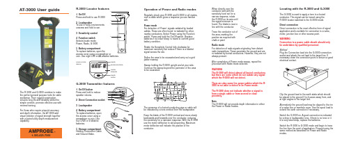
G-3000 Transmitter features1 On/Off buttonPress and hold to reduce speaker volume.2 Direct Connection socket3 Loudspeaker4 Battery compartment To replace batteries, open the access cover using a screwdriver or coin. Use four LR20 or D alkaline batteries.5 Storage compartment Holding Connection Cable and Ground Stake.Locating with the R-3000 and G-3000The G-3000 is used to apply a tone to a buried conductor. This signal can be traced using the R-3000 locator switched to the G-3000 mode.Direct connectionDirect connection is the most effective form of signal application and is suitable for connection to a valve,meter, junction box or other access point.WARNINGConnection to a power cable sheath should only be undertaken by qualified personnel.MethodPlug the Connection lead into the G-3000 connection socket and attach the red lead to the target line. Ifnecessary clean the connection point to ensure a good electrical contact.Clip the ground lead to the earth stake which should be placed in the ground 3 to 4 paces away from, and at right angles to the target line.Alternatively the ground lead may be clipped to the rim of a valve box or manhole cover. Use the spool lead to extend the earth connection if necessary.Switch the G-3000 on. A good connection is indicated by a drop in loudspeaker tone. if there is no tone or it is a very slow bleep, replace the batteries.Switch the R-3000 to G-3000 mode and begin to trace the line from the point of application. Pinpoint using the same method as described for Power and Radio modes.When directly over the conductor and with the sensitivity level set for a narrow response, rotate the R-3000 on its axis until the signal minimum isfound. The blade is now in line with the conductor.Trace the conductor out of the area, marking the position as required with chalk or paint Radio modeFor detection of radio signals originating from distant radio transmitters. These penetrate the ground and are re-radiated by buried conductors. However, they are not always present.After completion of Power mode sweep, repeat the procedure with Radio mode selected.WARNINGThe R-3000 will detect almost all buried conductors but there are some which do not radiate any signal which the R-3000 will not detect.There are also some live power cables which the R-3000 is not able to detect in he Power mode.The R-3000 does not indicate whether a signal is from a single cable or from several in close proximity.NoteThe R-3000 will not provide depth information in either the Power or Radio modes.Liquid crystal displayR-3000 Locator features1 On/OffPress and hold to use R-30002 LoudspeakerTo use in noisy environments unscrew and hold to ear.3 Sensitivity control 4 Function switch Selects locate mode:Power, Radio, G-30005 Battery compartmentTo replace batteries, open theaccess cover using a screwdriver orcoin. Use eight LR6 or AA alkaline batteries.AT-3000 User guideThe R-3000 and G-3000 combine to make the perfect general purpose tools for cable avoidance. Their rugged construction ensures long life and reliability whilst the simple controls promote effective use with minimal training.For those who require pinpoint accuracy and depth information, the AT-3000 add visual indiction of signal strength together with a buried utility depth measurement capability.5341252134mDepthMode/clockface Signal strength Depth buttonOperation of Power and Radio modesRegularly check your R-3000 and G-3000 in all modes,over a cable which gives a response you are familiar with.Power modeFor detection of ‘Power’signals radiated by loaded cables. These are often found ‘re-radiated’by other,nearby conductors. Select Power using the Function switch. Press and hold the On/Off switch. Replace batteries if no initial ‘bleep’is heard to confirm good battery condition.Rotate the Sensitivity Control fully clockwise formaximum sensitivity but reduce if there is a blanket signal across the site.Define the area to be excavated and carry out a grid pattern sweep.Sweep holding the R-3000 upright and at your side.Continue the sweep beyond the perimeter of the area to be excavated.AMPROBE1-305-423-7500®The presence of a buried conducting pipe or cable will be indicated by a tone emitted from the loudspeaker.Keep the blade of the R-3000 vertical and move slowly backwards and forwards over the conductor, reducing the sensitivity for a narrower response. With the R-3000use the meter deflection to aid pinpointing. Maximum meter deflection will indicate the position of the conductor.Optional AccessoriesUsing the optional* Signal Clamp SC-3000The Signal Clamp applies a G-3000 signal safely to a pipe or live cable of up to 76mm (3 inches) diameter,without interrupting the supply.MethodPlug the Clamp into the G-3000 Connection socket.Place the Clamp around the pipe or cable ensuring the jaws are closed. Switch the G-3000 on. Open and close the Clamp. If the jaws are closing correctly a drop in speaker tone will be heard.An earth connection is not necessary but efficientsignal transfer is only achieved if the target conductor is grounded at both ends. This is usually the case with power cables.InductionInduction is a convenient and quick way of applying the G-3000 signal to a pipe or cable where limited access does not permit direct connection or use of the Signal Clamp.Place the G-3000 over the assumed position of the conductor in the orientation shown.Start tracing the cable or pipe at least five paces from the G-3000 with the R-3000 in G-3000 mode. Working too close to the G-3000 may give false readings as the R-3000 will detect more signal directly from the G-3000than from the conductor.Do not attempt to take depth readings unless the distance between the R-3000 and G-3000 is greater than 30 paces (see “Taking depth readings using the R-3000”).Active search using Induction Placing the G-3000 on its side swamps an area with G-3000 signal.Alternatively, use a two man technique to search an area for buried utilities.Taking line depth measurement using the R-3000Depth measurement is only possible when using the R-3000 in the G-3000 mode.MethodLocate the utility as described previously.Ensure that thedepth measurement position is at least 30 paces from the G-3000, especially if signal application is by Induction method.Hold the R-3000 still,vertical and at right angles to the buried line.Momentarily depress the depth button. The display will show a moving clock face followed by the depth measurement.Taking Mouse depth measurements using the R-3000Depth measurement is only possible when using the R-3000 in the G-3000 mode with a Mouse transmitter.MethodLocate the main Mouse signal as previously described.Hold the R-3000 vertically and in line with the Mouse.Press and hold the depth button until ‘M’appears on the display. A clock face will appear in the top right hand corner of the display while the depth calculation is made. The approximate depth to the Mouse will then be displayed on the meter.R-3000 error codesIndicates very shallow conductor Indicates conductor out of range Indicates depth measurement attempted in R or P mode which is not available.WARNINGDo not use the R-3000 depth measurement to decide if mechanical digging over buried conductor is appropriate.ddm in 30 p a c e sr e c o mm e n d e dUsing the optional* Mouse Signal Transmitter M-3000The mouse is a small self-contained watertighttransmitter which can be detected by the R-3000 when switched to the G-3000 mode.MethodReplace the battery in the Mouse. Attach the Mouse to a drain rod using an appropriate connector.Place the Mouse on the ground, set the R-3000 to G-3000 mode and, whilst holding the R-3000 in line with the Mouse, check that a signal is being received.Insert the Mouse approximately 1m/yd into theduct/drain and adjust the R-3000 sensitivity to receive the signal.A ghost signal appears before and behind the main signal position. Reduce the R-3000 sensitivity to receive only the main signal.PeakGhostGhostReplacementsConnection Kit CK-3000(Includes connection cable and ground stake)AmprobeTel: 305 423 7500Fax:305 423 7554Technical Support:800 327 506090/NUG01AMP/0 11.00。
纠偏说明书

9.自动 对 中 键
[1] 编程键:用这四个键可以进行各种菜单的选择或设定的确认。 返回键 :按下此键可以返回到上一级菜单或返回到运行画面。 递增键 :菜单向上翻页或参数设置值加。 递减键 :菜单向下翻页或参数设置值减。 确认键 :进入编程菜单或确认设定参数。
[2] 手动纠偏模式键 按下 此键, 控 制器面 板 上手动 纠 偏指示 灯 (6) 亮 ,控制 器 进入手 动 纠偏模 式 。
[3] 执行机构:正常使用请按左 图所示接线。
外壳 接 地端子 进 行D类接地 。 其他使用功能请参阅说明 书的相关章节。
外壳上接地端
注意
切 勿 接 入A C 2 2 0 V或 3 8 0 V否 则 损 坏 产 品 。
WEB GUIDING CONTROLLER
·5·
第三章 编程方法
3.1 控制器菜单画面
·4·
第二章 安装与配线
2 . 3、 控 制 器 基 本 配 线
使 用K 5 0纠 偏 控 制 器,基 本 配 线 如 下 图 所 示 :
DATA+ 01 DATA- 02
+7V 03 COM 04 1RECE+ 05 1RECE- 06 1TRAM+ 07 1TRAM- 08 1LED+ 09 1LED- 10 SHIELD 11 2RECE+ 12 2RECE- 13 2TRAM+ 14 2TRAM- 15 2LED+ 16 2LED- 17
1、传感器 选择
本 纠 偏控制 器可以 配 合使用 多 种传感 器 :CC D光 电传感 器 、超 声 波传感 器 、红 外线传感器等。
初 始 设置为 :超声 波A。
01传感器选择
Standard3000中文操作手册part1
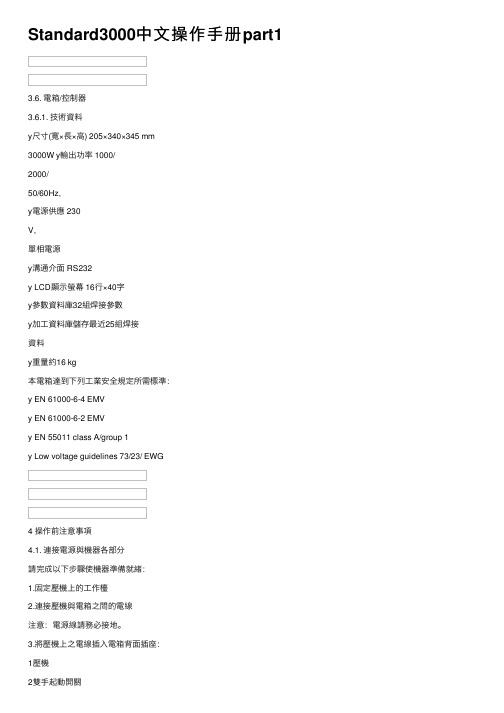
Standard3000中⽂操作⼿册part13.6. 電箱/控制器3.6.1. 技術資料y尺⼨(寬×⾧×⾼) 205×340×345 mm3000W y輸出功率 1000/2000/50/60Hz,y電源供應 230V,單相電源y溝通介⾯ RS232y LCD顯⽰螢幕 16⾏×40字y參數資料庫32組焊接參數y加⼯資料庫儲存最近25組焊接資料y重量約16 kg本電箱達到下列⼯業安全規定所需標準:y EN 61000-6-4 EMVy EN 61000-6-2 EMVy EN 55011 class A/group 1y Low voltage guidelines 73/23/ EWG4 操作前注意事項4.1. 連接電源與機器各部分請完成以下步驟使機器準備就緒:1.固定壓機上的⼯作檯2.連接壓機與電箱之間的電線注意:電源線請務必接地。
3.將壓機上之電線插⼊電箱背⾯插座:1壓機2雙⼿起動開關3RF (與換能器連接)4電源4.1.1. 主動溝通裝置5RS232插座 (9孔D-sub插座)6數位輸⼊ (25孔D-sub插座,序列埠)7數位輸出 (25孔D-sub插座,序列埠)其他資料請⾒第⼋章”資料分析”,插座配置請⾒第九章”主動溝通與信號傳送”。
4.1.2. 壓縮空氣源:最⼤7 bar;105 psi依下列指⽰轉動壓縮空氣閥(21):4.將壓縮空氣喉(21a)與壓縮空氣供應源連接。
5.將壓縮空氣閥(21)轉⾄⼯作位置。
注意:若輸⼊壓縮空氣壓⼒⼤於7 bar,附加安全氣閥會⾃動開啟釋放過多的空氣壓⼒。
4.1.3. 裝備隔⾳罩SSK-H1ADG電箱電源2數位輸⼊ (25孔D-sub插座,序列埠) 3數位輸出 (25孔D-sub插座,序列埠) 4壓機5雙⼿起動開關6RF (與換能器連接)拆除隔⾳罩後⽅⾯板可調整壓機,卸除或裝備隔⾳罩。
4.2. 操作及顯⽰元件4.2.1. 壓機1 換能器外罩內藏超⾳波發振系統及電源線。
BP3000使用手册
电源
关 开
准备 就绪 关 关
开关
开关
开开 开开 开 闪烁
开
纸张 关 开
关
闪烁 开 关 闪烁
用户 1/2 关
开/关
状态
打印机关闭或损坏
停止键被按下(脱机(Offline)状 态), 已放入纸张 停止键被按下(脱机(Offline)状 态), 没有放入纸张 打印机缺纸(脱机(Offline)状态), 要求放入纸张 联机(Online)状态,已放入纸张 联机(Online)状态,没有放入纸张 故障,在液晶显示上显示发生故障 的原因 通过系统控制:打印机由用户 1 或用户 2 使用
2.2 指示灯
5 个指示灯从左向右依次为电源、用户 1、准备就绪、纸张、用户 2。 含义如下:
电源灯 :指示电源是否接通。 用户 1 :由系统控制,显示打印机正被用户 1 使用。 准备就绪:指示打印机是否处于联机状态。 纸张 :指示打印机有纸或缺纸。 用户 2 :由系统控制,显示打印机正被用户 2 使用。
2. 4 启动时按键实现功能
2.4.1 设置清单打印功能
按 住 退 纸 (Eject)键开机直到机器有动作,启动测试打印打印功能,液晶显 示 中 显 示 文 字 装 入 介 质 ( LOAD PAPER)后,装入纸张后将打出设置清单。根据 打印出的设置清单您可以清楚当前打印机的各参数设置和固件版本。 2.4.2 倾印功能
(放入纸张)字样。 4. 插入一张 A4 大小(210mm*297mm)的纸到进纸器槽内。 5. 接 着 , 将 打 印 两 张 测 试 页 内 容 。
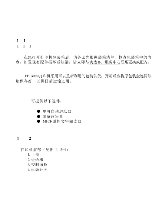
1. 6 打印机与主机连接 该打印机可通过 RS232 串行接口电缆或 Centronics 并行接口电缆连接到
- 1、下载文档前请自行甄别文档内容的完整性,平台不提供额外的编辑、内容补充、找答案等附加服务。
- 2、"仅部分预览"的文档,不可在线预览部分如存在完整性等问题,可反馈申请退款(可完整预览的文档不适用该条件!)。
- 3、如文档侵犯您的权益,请联系客服反馈,我们会尽快为您处理(人工客服工作时间:9:00-18:30)。
BF-3000型自动纠偏系统简易说明书一操作面板功能简介:
二.安装尺寸
三.菜单及参数说明
四.U形对射式传感器跟边跟边操作步骤1.跟边操作步骤
按下手动键
2 按下设置键
3
4 5 6
8
10 11 12
13
14
15
16 18
五.同轴反射式传感器跟线与跟边操作步骤1
按下手动键
2 按下设置键
3
4
5
6
7
8
9
10
2.1跟线AD上限与AD下限的设置
光斑
光斑AD下限的设置AD上限的设置
说明:先照在材料的空白位置设置AD上限值,再照在材料的线上设置AD下限值。
2.2跟边AD上限与AD下限的设置
光斑
光斑AD下限的设置AD上限的设置
说明:先照在导辊上设置AD上限,再照在材料上设置AD下限。
跟线事光斑照在线的左右两边,跟边时光斑一半照在材料上,一半照在导辊上。
常见异常现像解析:
联系方式:4008808630
注意:请务必保管好此操作说明书,以便需要时查阅,谢谢合作!。