Abstract Adaptive Video Streaming Pre-encoded MPEG-4 with Bandwidth Scaling
基于内容自适应的视频超分辨率算法-SRVC
基于内容⾃适应的视频超分辨率算法-SRVC1. 介绍论⽂全名是《Efficient Video Compression via Content-Adaptive Super-Resolution》,作者全部来⾃⿇省理⼯计算机科学与⼈⼯智能实验室(MIT CSAIL),这篇论⽂主要是使⽤视频超分辨率(video super-resolution)技术来完成视频压缩任务,从⽽应⽤于视频的传输(节省带宽)。
2. 算法详解2.1 传统视频编码管线众所周知,将图像序列转成⼀个视频可以⼤⼤减少数据存储量(绝⼤部分情况)。
但是,⽣成的视频如果要在⽹络上传播的话会严格收到⽹络带宽的限制。
在固定带宽(固定传输速率)的情况下,使⽤更⾼的视频压缩算法(同时保证视频质量不损失,或者损失在⼀定范围内),可以传输更⾼分辨率的视频。
⽐如,1M的带宽,使⽤某个视频压缩算法只能传输480P的视频,在使⽤了更加⾼效的另外⼀个视频压缩算法,可以传输720P了。
⽬前常⽤的视频压缩算法有H.264、H.265等。
这⾥以H.265为例,其⼯作原理⼤致如下:在上⾯加⼊超分的思想,就是先把1080P的视频下采样⾄480P,压缩传过去解码后,再⽤超分变回1080P的视频,⼤致流程如下这样的好处是视频压缩算法真正要压缩的其实是480P的视频,所以传输的数据量会⼤⼤减少。
坏处则是传输者在下采样视频的时候其实已经丢掉了⼀部分信息,⽽接收者最后获得的1080P视频的质量很⼤程度上依赖于超分算法的选择。
超分算法可以使⽤最简单的Bicubic(双三次插值)。
Bicubic⽹上的资料很多,简单来说它跟bilinear(双线性插值)⼀样,插值的结果依赖邻域的像素,也就是可以⽤图像中的卷积来完成。
但是Bicubic的卷积kernel是固定的,这就很不科学。
“科学”来讲,kernel应该根据图像中的不同区域产⽣不同的变化。
此外,视频经过H.265编码、解码后,已经不是原来的视频了(因为H.265是有损压缩),所以超分的过程还需要尽量恢复这⾥丢失的信息。
视频对象移除篡改的时空域定位被动取证

2020年7月Journal on Communications July 2020 第41卷第7期通信学报V ol.41No.7视频对象移除篡改的时空域定位被动取证陈临强1,杨全鑫2,袁理锋1,姚晔1,张祯1,吴国华1(1. 杭州电子科技大学网络空间安全学院,浙江杭州 310018;2. 杭州电子科技大学计算机学院,浙江杭州 310018)摘 要:针对视频被动取证领域中视频内容的真实性和完整性鉴定及篡改区域定位问题,提出了一种基于视频噪声流的深度学习检测算法。
首先,构建了基于空间富模型(SRM)和三维卷积(C3D)神经网络的特征提取器、帧鉴别器和基于区域建议网络(RPN)思想的空域定位器;其次,将特征提取器分别与帧鉴别器和空域定位器相结合,搭建出2个神经网络;最后,利用增强处理后的数据训练出2种深度学习模型,分别用于对视频篡改区域时域和空域的定位。
测试结果表明,时域定位的准确率提高到98.5%,空域定位与篡改区域标注平均交并比达49%,可以有效对该类篡改视频进行篡改区域时空域定位。
关键词:视频对象移除篡改;时空域定位;视频被动取证;三维卷积目标检测中图分类号:TP309文献标识码:Adoi: 10.11959/j.issn.1000-436x.2020151Passive forensic based on spatio-temporal localization ofvideo object removal tamperingCHEN Linqiang1, YANG Quanxin2, YUAN Lifeng1, YAO Ye1, ZHANG Zhen1, WU Guohua11. School of Cyberspace Security, Hangzhou Dianzi University, Hangzhou 310018, China2. School of Computer, Hangzhou Dianzi University, Hangzhou 310018, ChinaAbstract: To address the problem of identification of authenticity and integrity of video content and the location of video tampering area, a deep learning detection algorithm based on video noise flow was proposed. Firstly, based on SRM (spa-tial rich model) and C3D (3D convolution) neural network, a feature extractor, a frame discriminator and a RPN (region proposal network) based spatial locator were constructed. Secondly, the feature extractor was combined with the frame discriminator and the spatial locator respectively, and then two neural networks were built. Finally, two kinds of deep learning models were trained by the enhanced data, which were used to locate the tampered area in temporal domain and spatial domain respectively. The test results show that the accuracy of temporal-domain location is increased to 98.5%, and the average intersection over union of spatial localization and tamper area labeling is 49%, which can effectively lo-cate the tamper area in temporal domain and spatial domain.Key words: video object removal tampering, spatio-temporal localization, video passive forensic, object detection based on 3D convolution1引言随着数字视频处理技术的飞速发展和图像编辑软件的更新换代,篡改视频[1-3]变得随处可见。
直播技术的流媒体传输协议常见的直播流媒体传输协议介绍
直播技术的流媒体传输协议常见的直播流媒体传输协议介绍直播技术在现代社交媒体中的应用越来越广泛,为了实现高质量的流媒体传输,直播平台借助各种流媒体传输协议。
本文将介绍几种常见的直播流媒体传输协议,并对其特点进行分析。
一、RTMP协议RTMP(Real-Time Messaging Protocol)是一种实时消息传输协议,由Adobe开发。
它采用基于TCP的传输方式,在互联网传输中表现出良好的稳定性和实时性。
RTMP协议通过将音频、视频及元数据打包成小块传输,保证了传输的流畅性和稳定性。
RTMP协议被广泛应用于实时直播领域,尤其在低延迟的直播环境下表现出色。
二、HLS协议HLS(HTTP Live Streaming)协议是由Apple提出的流媒体传输协议。
HLS协议基于HTTP协议,将整个视频分成多个小的TS (Transport Stream)文件,通过HTTP协议逐个传输。
HLS协议适应性强,支持多种终端设备播放,并且能够自适应网络环境的变化。
这使得HLS成为了许多直播平台的首选协议。
三、DASH协议DASH(Dynamic Adaptive Streaming over HTTP)协议是一种动态自适应流媒体传输协议,由MPEG联盟制定。
DASH协议无需握手过程,通过HTTP协议动态获取数据,根据客户端自身的网络情况和解码能力选择相应的码率和片段进行播放。
DASH协议具有较好的抗丢包能力和适应性,能够在不同的网络环境下提供良好的用户体验。
四、FLV协议FLV(Flash Video)协议是一种用于传输视频和音频的流媒体传输协议,由Adobe Flash Player支持。
FLV协议将视频和音频数据打包成FLV文件进行传输,常用于Adobe Flash Player播放器的直播功能。
然而,由于Adobe Flash Player不再被主流浏览器支持,FLV协议的使用范围受到了限制。
五、WebSocket协议WebSocket协议是一种全双工通信协议,它可以在一个TCP连接上实现双向通信。
面向自适应码率视频直播的码率控制算法
面向自适应码率视频直播的码率控制算法詹亘;肖晶;陈宇静;陈军【摘要】在自适应码率视频直播过程中, 传统码率控制方法不能有效控制切片码率, 导致客户端播放器自适应判断失准, 出现卡顿.为此, 提出一种切片层级的码率控制算法.在切片内部使用基于帧类型的码率分配策略, 提出关键P帧的概念, 通过调整关键P帧的分布来优化不同视频内容下的码率分配.建立基于SATD和量化系数的线性预测模型, 利用模型迭代调整每行的量化系数, 进而控制整帧的编码大小.实验结果表明, 该算法可以准确控制切片码率, 保证视频质量.%As traditional rate control methods cannot effectively control the segment size in adaptivebit-rate live streaming, the bitrate adaption of video player is affected by the fluctuation of segment size, and then makes inaccurate decisions, resulting in the delay on the client side.To solve this problem, a segment level rate control algorithm is proposed.Bit allocation strategy based on frame type is used inside each segment.The concept of key P-frame is proposed and the distribution of key P-frame is adjusted to optimize the allocation under different video contents.At the same time, a linear prediction model based on SATD and Quantization Parameter (QP) is built, and the QP of each row is adjusted iteratively to control the coding size of the whole frame.Experimental results show that the proposed algorithm can control the bit-rate of segment precisely and ensure the video quality.【期刊名称】《计算机工程》【年(卷),期】2019(045)003【总页数】5页(P268-272)【关键词】视频直播;自适应码率;视频编码;码率控制;量化参数【作者】詹亘;肖晶;陈宇静;陈军【作者单位】武汉大学计算机学院国家多媒体软件工程研究中心,武汉 430079;武汉大学计算机学院国家多媒体软件工程研究中心,武汉 430079;武汉大学计算机学院国家多媒体软件工程研究中心,武汉 430079;武汉大学计算机学院国家多媒体软件工程研究中心,武汉 430079【正文语种】中文【中图分类】TN919.80 概述随着流媒体技术的不断发展、移动通信网络环境的改善以及智能终端设备的普及,视频直播因其实时性和互动性,成为互联网内容生产的重要载体。
博士安全FLEXIDOME IP 7000 VR全能防刺激球机器人视频摄像头说明书

uAesthetic vandal-resistant enclosure, suitable for indoor or outdoor applicationsuContent-based scene analysis optimizes the image processinguIntelligent noise reduction reduces bandwidth and storage requirements by up to 50%uEasy to install with auto zoom/focus SR lens, wizard and pre-configured modesThe FLEXIDOME IP 7000 VR dome camera combines intelligence with adaptive video processing to provide you with superior HD image quality. This true day/night camera provides high resolution video, tuned for 24x7 applications.The aesthetic vandal-resistant housing makes the camera suitable for indoor or outdoor installation.System overviewCompared to SD cameras, this camera offers, at no higher cost, motorized autofocus, higher resolution,better sensitivity, higher frame rates, and improved picture quality, and is still more bandwidth-efficient.Video storage costs are significantly reduced.FunctionsContent Based Imaging TechnologyContent Based Imaging Technology (CBIT) is used to radically improve image quality in all lighting conditions and to identify areas for enhancedprocessing. The camera examines the scene using Intelligent Video Analysis (IVA) and provides feedback to re-tune the image processing. This provides better detail in the areas that matter and better all-roundperformance. With IVA, the Intelligent Auto Exposure technology, for example, allows you to view moving objects in bright and dark areas of a scene.Intelligent Dynamic Noise Reduction reduces bandwidth and storage requirementsThe camera uses Intelligent Dynamic Noise Reduction which actively analyzes the contents of a scene and reduces noise artifacts accordingly.The low-noise image and the efficient H.264compression technology provide clear images while reducing bandwidth and storage by up to 50%compared to other H.264 cameras. This results in reduced-bandwidth streams that still retain a high image quality and smooth motion. The cameraprovides the most usable image possible by cleverly optimizing the detail-to-bandwidth ratio.Area-based encodingArea-based encoding is another feature which reduces bandwidth. Compression parameters for up to eight user-definable regions can be set. This allowsuninteresting regions to be highly compressed, leaving more bandwidth for important parts of the scene.The average typical optimized bandwidth in kbits/s for various image rates is shown in the table:Multiple streamsThe innovative multi-streaming feature delivers various H.264 streams together with an M‑JPEG stream. These streams facilitate bandwidth-efficient viewing and recording as well as integration with third-party video management systems.An upright mode can be selected for the second stream. In this mode an image of 400 x 720 (9:16 aspect ratio) is cropped from the full sensor image. When the scene to be monitored is suitable to this mode, the bandwidth and storage requirements are reduced.Regions of interest and E-PTZRegions of Interest (ROI) can be user defined. The remote E-PTZ (Electronic Pan, Tilt and Zoom) controls allow you to select specific areas of the parent image. These regions produce separate streams for remote viewing and recording. These streams, together with the main stream, allow the operator to separately monitor the most interesting part of a scene while still retaining situational awareness.With IVA, Intelligent Tracking can follow objects within the defined regions of interest. Intelligent Tracking can autonomously detect and track moving objects or the user can click on an object which the tracker will then follow.Flexible lens choiceThe camera comes with a choice of AVF (Automatic Varifocal) lenses for easy installation. These SR (Super Resolution) lenses have an advanced iris design to ensure that the high resolution HD sensor produces the sharpest image possible, even in the corners. Simple set-upThe camera has a very intuitive user interface that allows fast and easy configuration. Configurable scene modes are provided with the best settings for a variety of applications.•Indoor – general day-to-night changes in an indoorenvironment without sun highlights or street lighting effects.•Outdoor – general day-to-night changes in an outdoor environment with sun highlights and street lightingeffects.•Traffic – for monitoring traffic movement on roads or parking lots. It can also be used in industrialapplications where fast moving objects are to bemonitored. Motion artifacts are minimized.•Night-optimized – optimized for details in low lightenvironments.•Intelligent AE – optimized for scenes with fluctuating front and back light caused by sunlight or otherilluminated objects in the scene.•Vibrant – enhanced contrast, sharpness andsaturation.•Low bit rate – reduces bandwidth requirements.•Sports and gaming – high-speed capture, andimproved color rendition and sharpness.•Retail – improved color rendition and sharpness with reduced bandwidth requirements.Storage managementRecording management can be controlled by the Bosch Video Recording Manager (VRM) or the camera can use iSCSI targets directly without any recording software.Edge recordingInsert a memory card into the card slot to store up to 2 TB of local alarm recording. Pre-alarm recording in RAM reduces recording bandwidth on the network, and extends the effective life of the memory card. Video analyticsWith built-in video content analysis, the camera reinforces the Intelligence-at-the-Edge concept where edge devices become increasingly intelligent. The MOTION+ video motion analysis system that is built into all camera versions is the perfect solution for applications where standard video content analysis features are required.The IVA version of the camera uses the latest generation of the Bosch Intelligent Video Analysis (IVA) software. This IVA system is the guard-assistant system of choice when reliable indoor or outdoor video analytics is needed. The state-of-the-art system reliably detects, tracks, and analyzes moving objects while suppressing unwanted alarms from spurious sources in the image.The face detection feature detects faces in the scene and forwards a high quality JPEG image of the best shot of each face when the face disappears from the scene.Retrospective forensic search capabilities are available remotely from the web browser or theBosch Video Client.Cloud-based servicesThe camera supports time-based or alarm-based JPEG posting to four different accounts. These accounts can address FTP servers or cloud-based storage facilities (for example, Dropbox). Video clips or JPEG images can also be exported to these accounts.Alarms can be set up to trigger an e-mail or SMS notification so you are always aware of abnormal events.Access securityPassword protection with three levels and 802.1x authentication is supported. To secure Web browser access, use HTTPS with a SSL certificate stored in thecamera. The video and audio communication channels can be independently AES encrypted with 128-bit keys by installing the optional encryption site license. Complete viewing softwareThere are many ways to access the camera’s features: using a web browser, with the Bosch Video Management System, with the free-of-chargeBosch Video Client, with the video security mobile app, or via third-party software.Video security AppThe Bosch video security mobile App has been developed to enable Anywhere access to HD surveillance images allowing you to view live images from any location. The App is designed to give you complete control of all your cameras, from panning and tilting to zoom and focus functions. It’s like taking your control room with you.This App, together with the separately available Bosch transcoder, will allow you to fully utilize our dynamic transcoding features so you can play back images even over low-bandwidth connections.System integrationThe camera conforms to the ONVIF Profile S specification. Compliance with this standard guarantees interoperability between network video products regardless of manufacturer.Third-party integrators can easily access the internal feature set of the camera for integration into large projects. Visit the Bosch Integration Partner Program (IPP) website () for more information.Easy installationPower for the camera can be supplied via a Power-over-Ethernet compliant network cable connection. With this configuration, only a single cable connection is required to view, power, and control the camera. Using PoE makes installation easier and more cost-effective, as cameras do not require a local power source.The camera can also be supplied with power from+12 VDC/24 VAC power supplies. To increase system reliability, the camera can be simultaneously connected to both PoE and +12 VDC/24 VAC supplies. Additionally, uninterruptible power supplies (UPS) can be used, which will allow continuous operation, even during a power failure.The automatic zoom/focus lens wizard makes it easy for an installer to accurately zoom and focus the camera for both day and night operation. The wizard is activated from the PC or from the on-board camera push button making it easy to choose the workflow that suits best.The AVF (Automatic Varifocal) feature means that the zoom can be changed without opening the camera. The automatic motorized zoom/focus adjustment with 1:1 pixel mapping ensures the camera is always accurately focused.Hybrid modeAn analog video output enables the camera to operate in hybrid mode. This mode provides simultaneous high resolution HD video streaming and an analog video output via a BNC connector. The hybrid functionality offers an easy migration path from legacy CCTV to a modern IP-based system.Aesthetic vandal resistant designThe compact aesthetic design is suitable for installations where housing size and appearance are important. The cast-aluminum housing, polycarbonate window, and hardened inner liner can withstand the equivalent of 55 kg (120 lbs) of force (IK10). The camera is protected against water and dust to IP 66 (NEMA Type 4X) standards. Using the proprietary pan/ tilt/rotation mechanism, installers can select the exact field of view. Mounting options are numerous, including surface, wall, corner, and suspended-ceiling mounting.Typical applications•Retail, banks•Stadiums•Schools•Care facilities•Traffic monitoring (air, land and sea)•Hotels, bars and nightclubs•Commercial and government buildings•City surveillance and safety•Border controlHD standardsComplies with the SMPTE 274M-2008 Standard in:–Resolution: 1920x1080–Scan: Progressive–Color representation: complies with ITU-R BT.709–Aspect ratio: 16:9–Frame rate: 25 and 30 frames/sComplies with the 296M-2001 Standard in:–Resolution: 1280x720–Scan: Progressive–Color representation: complies with ITU-R BT.709–Aspect ratio: 16:9–Frame rate: 25 and 30 frames/sStandards* Chapters 7 and 8 (mains voltage supply requirement) are not applicable to the camera. However, if the system in which this camera is used needs to comply with this standard, then any power supplies used must comply with this standard.Installation/configuration notesDimensions flush mountingmm (in) Dimensions surface mountingØ158 (6.22)mm (i n)VDA-WMT-DOME –Pendant Wall Mount205 (8.07)mm (in)247(9.71) LTC 9213/01 Pole Mount AdapterHolemm(in.)mm (in)17(4.19)Parts includedTechnical specificationsSensitivity – (3200K, reflectivity 89%, 1/60, 30IRE)Lens 3 - 9 mm (F1.2)Resolutions (H x V)Ordering informationFLEXIDOME IP 7000 VRHigh-performance IP dome camera for HD surveillance. 1080p30; Hybrid; IP66; IK10; IDNR; ROI; H.264 quad-streaming; cloud services; free viewing Apps; 3 to9 mm SR lens; MOTION+Order number NIN-832-V03PFLEXIDOME IP 7000 VRHigh-performance IP dome camera for HD surveillance. 1080p30; Hybrid; IP66; IK10; IDNR; IAE; ROI; H.264 quad-streaming; cloud services; free viewing Apps; 3 to 9 mm SR lens; IVAOrder number NIN-832-V03IPFLEXIDOME IP 7000 VRHigh-performance IP dome camera for HD surveillance. 1080p30; Hybrid; IP66; IK10; IDNR; ROI; H.264 quad-streaming; cloud services; free viewing Apps; 3 to9 mm SR lens; MOTION+; SMBOrder number NIN-832-V03PSFLEXIDOME IP 7000 VRHigh-performance IP dome camera for HD surveillance. 1080p30; Hybrid; IP66; IK10; IDNR; IAE; ROI; H.264 quad-streaming; cloud services; free viewing Apps; 3 to 9 mm SR lens; IVA; SMBOrder number NIN-832-V03IPSFLEXIDOME IP 7000 VRHigh-performance IP dome camera for HD surveillance. 1080p30; Hybrid; IP66; IK10; IDNR; ROI; H.264 quad-streaming; cloud services; free viewing Apps; 10 to23 mm SR lens; MOTION+Order number NIN-832-V10PFLEXIDOME IP 7000 VRHigh-performance IP dome camera for HD surveillance. 1080p30; Hybrid; IP66; IK10; IDNR; IAE; ROI; H.264 quad-streaming; cloud services; free viewing Apps; 10 to 23 mm SR lens; IVAOrder number NIN-832-V10IPFLEXIDOME IP 7000 VRHigh-performance IP dome camera for HD surveillance. 1080p30; Hybrid; IP66; IK10; IDNR; ROI; H.264 quad-streaming; cloud services; free viewing Apps; 10 to23 mm SR lens; MOTION+; SMBOrder number NIN-832-V10PS FLEXIDOME IP 7000 VRHigh-performance IP dome camera for HD surveillance. 1080p30; Hybrid; IP66; IK10; IDNR; IAE; ROI; H.264 quad-streaming; cloud services; free viewing Apps; 10 to 23 mm SR lens; IVA; SMBOrder number NIN-832-V10IPSAccessoriesVDA-WMT-DOME Wall Pendant Mount BracketWall pendant mount bracket for FlexiDome cameras Order number VDA-WMT-DOMEVDA-CMT-DOME Corner Mount BracketCorner mount bracket for FlexiDome camerasOrder number VDA-CMT-DOMEVDA-PMT-DOME Pendant Pipe Mount Bracket Pendant pipe mount bracket for FlexiDome cameras Order number VDA-PMT-DOMELTC 9213/01 Pole Mount AdapterFlexible pole mount adapter for camera mounts (use together with the appropriate wall mount adapter). Max. 9 kg (20 lb); 3 to 15 inch diameter pole; stainless steel strapsOrder number LTC 9213/01VDA-PLEN-DOME In-ceiling Housing for Plenums Kit FLEXIDOME in-ceiling housing installation kit (plenum-rated) for various FLEXIDOME camerasOrder number VDA-PLEN-DOMEVGA-IC-SP In-ceiling Support KitSuspended ceiling support kit for FLEXIDOME VR cameras (requires VDA-PLEN-DOME kit) and AUTODOME 100/600/7000 cameras.Order number VGA-IC-SPUPA-2420-50 Power SupplyPower supply for cameras. 220 VAC, 50 Hz In; 24 VAC, 20 VA OutOrder number UPA-2420-50UPA-2430-60 Power SupplyPower supply for camera. 120 VAC, 60 Hz; 24 VAC,30 VA OutOrder number UPA-2430-60UPA-2450-50 Power Supply, 220 V, 50 HzIndoor power supply for camera. 220 VAC, 50 Hz In; 24 VAC, 50 VA OutOrder number UPA-2450-50UPA-2450-60 Power Supply, 120 V, 60 HzIndoor power supply for camera. 120 VAC, 60 Hz In; 24 VAC, 50 VA OutOrder number UPA-2450-60VDA-455TBL Tinted bubbleTinted bubble for FlexiDome seriesOrder number VDA-455TBLVDA-455CBL Clear bubbleClear Bubble for FlexiDome seriesOrder number VDA-455CBLS1460 Service/Monitor Cable2.5 mm jack to BNC video connector cable. 1 mOrder number S1460VIDEOJET XTC XF Video TranscoderHigh-performance video transcoder. H.264; CF cardslot; ROI; max resolution 1080p; 2 channelsOrder number VJT-XTCXFSurface Mount Box FLEXIDOME VRSurface Mount Box for FLEXIDOME VR CamerasOrder number VDA-455SMB-IPNIN-DMY Dummy CameraFLEXIDOME VR family dummy cameraOrder number NIN-DMYSoftware OptionsBVIP AES 128 Bit EncryptionSite licence for BVIP AES 128‑bit encryption. Enablesencrypted communication between BVIP devices andmanagement stationsOrder number MVS-FENC-AESRepresented by:Americas:Europe, Middle East, Africa:Asia-Pacific:China:America Latina:Bosch Security Systems, Inc. 130 Perinton Parkway Fairport, New York, 14450, USA Phone: +1 800 289 0096 Fax: +1 585 223 9180***********************.com Bosch Security Systems B.V.P.O. Box 800025617 BA Eindhoven, The NetherlandsPhone: + 31 40 2577 284Fax: +31 40 2577 330******************************Robert Bosch (SEA) Pte Ltd, SecuritySystems11 Bishan Street 21Singapore 573943Phone: +65 6571 2808Fax: +65 6571 2699*****************************Bosch (Shanghai) Security Systems Ltd.203 Building, No. 333 Fuquan RoadNorth IBPChangning District, Shanghai200335 ChinaPhone +86 21 22181111Fax: +86 21 22182398Robert Bosch Ltda Security Systems DivisionVia Anhanguera, Km 98CEP 13065-900Campinas, Sao Paulo, BrazilPhone: +55 19 2103 2860Fax: +55 19 2103 2862*****************************© Bosch Security Systems 2015 | Data subject to change without notice 5288219275 | en, V15, 05. Mar 2015。
web播放rtsp方案
web播放rtsp方案Web播放RTSP方案是指使用Web技术实现对RTSP流的播放。
RTSP(Real-Time Streaming Protocol)是一种用于音频、视频和其他流媒体数据传输的网络协议。
而Web技术则是常用于浏览器上的应用程序开发的一系列工具和技术。
目前,有两种常见的Web播放RTSP方案:使用WebRTC和使用HTTP流媒体服务器。
首先,WebRTC(Web Real-Time Communication)是一种基于Web 浏览器的实时通信技术,支持音频、视频和数据的传输。
WebRTC可以轻松地实现Web播放RTSP,其中包括两个关键部分:媒体传输控制器(MTC)和媒体传输器(MT)。
MTC负责控制RTSP会话的建立和维护,而MT则负责处理音频和视频的传输。
使用WebRTC实现的Web播放RTSP方案具有较低的延迟和较高的性能,适用于实时传输和即时通信应用。
其次,使用HTTP流媒体服务器也是一种常见的Web播放RTSP方案。
HTTP流媒体服务器是在服务器端将RTSP流转换为HTTP流,并通过HTTP协议传输到Web浏览器的技术。
在这种方案中,RTSP流会被转换为HLS(HTTP Live Streaming)或者DASH(Dynamic Adaptive Streaming over HTTP)格式的流,然后通过HTTP协议传输到浏览器。
Web浏览器可以使用HTML5的video标签来播放这些流。
相对于使用WebRTC,使用HTTP流媒体服务器的Web播放RTSP方案实现更为简单,适用于较大规模的流媒体应用。
总结而言,Web播放RTSP方案可以通过使用WebRTC或者HTTP 流媒体服务器实现。
WebRTC方案适用于实时通信和即时通信应用,具有较低延迟和较高性能。
而使用HTTP流媒体服务器的方案相对简单,适用于较大规模的流媒体应用。
具体采用哪种方案,应根据具体需求和应用场景来选择。
H.264标准中SP帧无缝切换技术的研究与实现

摘要近年来,随着宽带网络的发展和多媒体技术的进步,以及用户对网上多媒体信息需求的增长,视频流媒体技术受到了越来越多的关注。
为了提高压缩效率和增加网络友好性,H.264视频编码标准引入了一些新特色,其中包括新编码类型SP帧(和sI帧),sP帧(SP,SwitchingPrcdictive—frame)的主要特色:不同参考帧可以解码出相同重构帧。
因此利用sP帧技术生成的码流,能够在不同码率的码流间进行无缝切换,从而服务器能够根据用户的连接速度提供最好质量的服务。
本文论述了一个基于sP帧技术的码流无缝切换系统的设计与实现。
在该系统中,首先,对SP帧的性质和编解码方寨做了深入研究。
假定同一个序列以不同的码率编码成两个码流.在每个码流中切换点位置处的图象编码成SP帧,称为PrimarySP帧,对于每个PrimarySP帧,有个相应的SecondarySP帧,这个SecondarySP帧与PrimarySP帧有等同的重构帧,SecondarySP只在码流切换时发送(称为切换帧)。
H.264标准的JM模型只实现了PrimarySP帧的编解码,~次编码仅完成一条码流,而对SecondarySP帧的编码环境设置和编码算法都没有实现。
本文从JvT提案描述的SecondarySP帧的粗略框架出发,围绕“无缝切换”的中心目的,对图像的帧内宏块以“拷贝”的特殊形式编码.帧间宏块以新框架编码,同时对特殊的SKIP编码模式考虑适用性,以及滤波器的更新等,详细设计了一个SecondarySP帧的编码算法。
第二,针对“码流切换”的研究重点,本文提出了一种高效的智能流文件框架。
从“快速,准确无误”的根本出发,对不同码率的基本码流块,码流间的切换帧块,关键帧块,在文件中进行合理安排。
此框架所产生的智能流文件结构清晰,管理方便,适用于常见流媒体服务器。
结台上述两个技术,最终实现了“~次编码可完成多条码流”且“多条码流可无缝切换”的系统。
自适应分割的视频点云多模式帧间编码方法
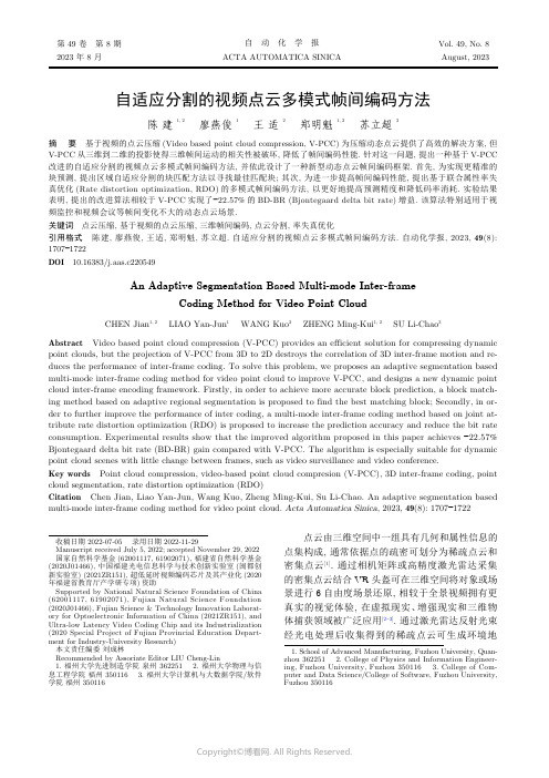
自适应分割的视频点云多模式帧间编码方法陈 建 1, 2廖燕俊 1王 适 2郑明魁 1, 2苏立超3摘 要 基于视频的点云压缩(Video based point cloud compression, V-PCC)为压缩动态点云提供了高效的解决方案, 但V-PCC 从三维到二维的投影使得三维帧间运动的相关性被破坏, 降低了帧间编码性能. 针对这一问题, 提出一种基于V-PCC 改进的自适应分割的视频点云多模式帧间编码方法, 并依此设计了一种新型动态点云帧间编码框架. 首先, 为实现更精准的块预测, 提出区域自适应分割的块匹配方法以寻找最佳匹配块; 其次, 为进一步提高帧间编码性能, 提出基于联合属性率失真优化(Rate distortion optimization, RDO)的多模式帧间编码方法, 以更好地提高预测精度和降低码率消耗. 实验结果表明, 提出的改进算法相较于V-PCC 实现了−22.57%的BD-BR (Bjontegaard delta bit rate)增益. 该算法特别适用于视频监控和视频会议等帧间变化不大的动态点云场景.关键词 点云压缩, 基于视频的点云压缩, 三维帧间编码, 点云分割, 率失真优化引用格式 陈建, 廖燕俊, 王适, 郑明魁, 苏立超. 自适应分割的视频点云多模式帧间编码方法. 自动化学报, 2023, 49(8):1707−1722DOI 10.16383/j.aas.c220549An Adaptive Segmentation Based Multi-mode Inter-frameCoding Method for Video Point CloudCHEN Jian 1, 2 LIAO Yan-Jun 1 WANG Kuo 2 ZHENG Ming-Kui 1, 2 SU Li-Chao 3Abstract Video based point cloud compression (V-PCC) provides an efficient solution for compressing dynamic point clouds, but the projection of V-PCC from 3D to 2D destroys the correlation of 3D inter-frame motion and re-duces the performance of inter-frame coding. To solve this problem, we proposes an adaptive segmentation based multi-mode inter-frame coding method for video point cloud to improve V-PCC, and designs a new dynamic point cloud inter-frame encoding framework. Firstly, in order to achieve more accurate block prediction, a block match-ing method based on adaptive regional segmentation is proposed to find the best matching block; Secondly, in or-der to further improve the performance of inter coding, a multi-mode inter-frame coding method based on joint at-tribute rate distortion optimization (RDO) is proposed to increase the prediction accuracy and reduce the bit rate consumption. Experimental results show that the improved algorithm proposed in this paper achieves −22.57%Bjontegaard delta bit rate (BD-BR) gain compared with V-PCC. The algorithm is especially suitable for dynamic point cloud scenes with little change between frames, such as video surveillance and video conference.Key words Point cloud compression, video-based point cloud compresion (V-PCC), 3D inter-frame coding, point cloud segmentation, rate distortion optimization (RDO)Citation Chen Jian, Liao Yan-Jun, Wang Kuo, Zheng Ming-Kui, Su Li-Chao. An adaptive segmentation based multi-mode inter-frame coding method for video point cloud. Acta Automatica Sinica , 2023, 49(8): 1707−1722点云由三维空间中一组具有几何和属性信息的点集构成, 通常依据点的疏密可划分为稀疏点云和密集点云[1]. 通过相机矩阵或高精度激光雷达采集的密集点云结合VR 头盔可在三维空间将对象或场景进行6自由度场景还原, 相较于全景视频拥有更真实的视觉体验, 在虚拟现实、增强现实和三维物体捕获领域被广泛应用[2−3]. 通过激光雷达反射光束经光电处理后收集得到的稀疏点云可生成环境地收稿日期 2022-07-05 录用日期 2022-11-29Manuscript received July 5, 2022; accepted November 29, 2022国家自然科学基金(62001117, 61902071), 福建省自然科学基金(2020J01466), 中国福建光电信息科学与技术创新实验室(闽都创新实验室) (2021ZR151), 超低延时视频编码芯片及其产业化(2020年福建省教育厅产学研专项)资助Supported by National Natural Science Foundation of China (62001117, 61902071), Fujian Natural Science Foundation (2020J01466), Fujian Science & Technology Innovation Laborat-ory for Optoelectronic Information of China (2021ZR151), and Ultra-low Latency Video Coding Chip and its Industrialization (2020 Special Project of Fujian Provincial Education Depart-ment for Industry-University Research)本文责任编委 刘成林Recommended by Associate Editor LIU Cheng-Lin1. 福州大学先进制造学院 泉州 3622512. 福州大学物理与信息工程学院 福州 3501163. 福州大学计算机与大数据学院/软件学院 福州 3501161. School of Advanced Manufacturing, Fuzhou University, Quan-zhou 3622512. College of Physics and Information Engineer-ing, Fuzhou University, Fuzhou 3501163. College of Com-puter and Data Science/College of Software, Fuzhou University,Fuzhou 350116第 49 卷 第 8 期自 动 化 学 报Vol. 49, No. 82023 年 8 月ACTA AUTOMATICA SINICAAugust, 2023图, 以实现空间定位与目标检测等功能, 业已应用于自动驾驶、无人机以及智能机器人等场景[4−7]. 但相较于二维图像, 点云在存储与传输中的比特消耗显著增加[8], 以经典的8i 动态点云数据集[9]为例, 在每秒30帧时的传输码率高达180 MB/s, 因此动态点云压缩是对点云进行高效传输和处理的前提.N ×N ×N 3×3×3为了实现高效的动态点云压缩, 近年来, 一些工作首先在三维上进行帧间运动估计与补偿, 以充分利用不同帧之间的时间相关性. 其中, Kammerl 等[10]首先提出通过构建八叉树对相邻帧进行帧间差异编码, 实现了相较于八叉树帧内编码方法的性能提升; Thanou 等[11]则提出将点云帧经过八叉树划分后, 利用谱图小波变换将三维上的帧间运动估计转换为连续图之间的特征匹配问题. 然而, 上述方法对帧间像素的运动矢量估计不够准确. 为了实现更精确的运动矢量估计, Queiroz 等[12]提出一种基于运动补偿的动态点云编码器, 将点云体素化后进行块划分, 依据块相关性确定帧内与帧间编码模式, 对帧间编码块使用提出的平移运动模型改善预测误差; Mekuria 等[13]则提出将点云均匀分割为 的块, 之后将帧间对应块使用迭代最近点(Iterative closest point, ICP)[14]进行运动估计,以进一步提高帧间预测精度; Santos 等[15]提出使用类似于2D 视频编码器的N 步搜索算法(N-step search, NSS), 在 的三维块区域中迭代寻找帧间对应块, 而后通过配准实现帧间编码. 然而,上述方法实现的块分割破坏了块间运动相关性, 帧间压缩性能没有显著提升.为了进一步提高动态点云压缩性能, 一些工作通过将三维点云投影到二维平面后组成二维视频序列, 而后利用二维视频编码器中成熟的运动预测与补偿算法, 实现三维点云帧间预测. 其中, Lasserre 等[16]提出基于八叉树的方法将三维点云投影至二维平面, 之后用二维视频编码器进行帧间编码; Bud-agavi 等[17]则通过对三维上的点进行二维平面上的排序, 组成二维视频序列后利用高效视频编码器(High efficiency video coding, HEVC)进行编码.上述方法在三维到二维投影的过程中破坏了三维点间联系, 重构质量并不理想. 为改善投影后的点间联系, Schwarz 等[18]通过法线将点映射于圆柱体上确保点间联系, 对圆柱面展开图使用二维视频编码以提高性能. 但在圆柱上的投影使得部分点因遮挡丢失, 影响重构精度. 为尽可能保留投影点数, Mam-mou 等[19]根据点云法线方向与点间距离的位置关系, 将点云划分为若干Patch, 通过对Patch 进行二维平面的排列以减少点数损失, 进一步提高了重构质量.基于Patch 投影后使用2D 视频编码器进行编码, 以实现二维上的帧间运动预测与补偿的思路取得了最优的性能, 被运动图像专家组(Moving pic-ture experts group, MPEG)正在进行的基于视频的点云压缩(Video-based point cloud compres-sion, V-PCC)标准[20]所采纳, 但将Patch 从三维到二维的投影导致三维运动信息无法被有效利用, 使得帧间压缩性能提升受到限制. 针对这一问题, 一些工作尝试在V-PCC 基础上实现三维帧间预测,其中, Li 等[21]提出了一种三维到二维的运动模型,利用V-PCC 中的几何与辅助信息推导二维运动矢量以实现帧间压缩性能改善, 但通过二维推导得到的三维运动信息并不完整, 导致运动估计不够准确.Kim 等[22]提出通过点云帧间差值确定帧内帧与预测帧, 帧内帧用V-PCC 进行帧内编码, 预测帧依据前帧点云进行运动估计后对残差进行编码以实现运动补偿, 但残差编码依旧消耗大量比特. 上述方法均在V-PCC 基础上实现了三维点云的帧间预测,但无论是基于二维的三维运动推导还是帧间残差的编码, 性能改善都比较有限.在本文的工作中, 首先, 为了改善三维上实现运动估计与补偿中, 块分割可能导致的运动相关性被破坏的问题, 本文引入了KD 树(K-dimension tree,KD Tree)思想, 通过迭代进行逐层深入的匹配块分割, 并定义分割块匹配度函数以自适应确定分割的迭代截止深度, 进而实现了更精准的运动块搜索;另外, 针对V-PCC 中二维投影导致三维运动信息无法被有效利用的问题, 本文提出在三维上通过匹配块的几何与颜色两种属性进行相似性判别, 并设计率失真优化(Rate distortion optimization, RDO)模型对匹配块分类后进行多模式的帧间编码, 实现了帧间预测性能的进一步改善. 实验表明, 本文提出的自适应分割的视频点云多模式帧间编码方法在与最新的V-PCC 测试软件和相关文献的方法对比中均取得了BD-BR (Bjontegaard delta bit rate)的负增益. 本文的主要贡献如下:1)提出了针对动态点云的新型三维帧间编码框架, 通过自动编码模式判定、区域自适应分割、联合属性率失真优化的多模式帧间编码、结合V-PCC 实现了帧间编码性能的提升;2)提出了一种区域自适应分割的块匹配方法,以寻找帧间预测的最佳匹配块, 从而改善了均匀分割和传统分割算法导致运动相关性被破坏的问题;3)提出了一种基于联合属性率失真优化模型的多模式帧间编码方法, 在改善预测精度的同时显著减少了帧间编码比特.1 基于视频的点云压缩及其问题分析本文所提出的算法主要在V-PCC 基础上进行1708自 动 化 学 报49 卷三维帧间预测改进, 因此本节对V-PCC 的主要技术做简要介绍, 并分析其不足之处. 其中, V-PCC 编码框架如图1所示.图 1 V-PCC 编码器框架Fig. 1 V-PCC encoder diagram首先, V-PCC 计算3D 点云中每个点的法线以确定最适合的投影面, 进而将点云分割为多个Patch [23].接着, 依据对应Patch 的位置信息, 将其在二维平面上进行紧凑排列以完成对Patch 的打包. 之后,依据打包结果在二维上生成对应的图像, 并使用了几何图、属性图和占用图分别表示各点的坐标、颜色及占用信息. 鉴于Patch 在二维的排列不可避免地存在空像素点, 因此需要占用图表示像素点的占用与否[24]; 由于三维到二维的投影会丢失一个维度坐标信息, 因此使用几何图将该信息用深度形式进行表示; 为了实现动态点云的可视化, 还需要一个属性图用于表示投影点的颜色属性信息. 最后, 为了提高视频编码器的压缩性能, 对属性图和几何图的空像素进行了填充和平滑处理以减少高频分量; 同时, 为了缓解重构点云在Patch 边界可能存在的重叠或伪影, 对重构点云进行几何和属性上的平滑滤波处理[25]. 通过上述步骤得到二维视频序列后, 引入二维视频编码器(如HEVC)对视频序列进行编码.V-PCC 将动态点云帧进行二维投影后, 利用成熟的二维视频编码技术实现了动态点云压缩性能的提升. 但是, V-PCC 投影过程将连续的三维物体分割为多个二维子块, 丢失了三维上的运动信息,使得三维动态点云中存在的时间冗余无法被有效利用. 为了直观展示投影过程导致的运动信息丢失,图2以Longdress 数据集为例, 展示了第1 053和第1 054两相邻帧使用V-PCC 投影得到的属性图.观察图2可以发现, 部分在三维上高度相似的区域,如图中标记位置1、2与3所对应Patch, 经二维投影后呈现出完全不同的分布, 该结果使得二维视频编码器中帧间预测效果受到限制, 不利于压缩性能的进一步提升.2 改进的动态点云三维帧间编码为了在V-PCC 基础上进一步降低动态点云的时间冗余性, 在三维上进行帧间预测和补偿以最小化帧间误差, 本文提出了一个在V-PCC 基础上改进的针对动态点云的三维帧间编码框架, 如图3所示. 下面对该框架基本流程进行介绍.首先, 在编码端, 我们将输入的点云序列通过模块(a)进行编码模式判定, 以划分帧内帧与预测帧. 其思想与二维视频编码器类似, 将动态点云划分为多组具有运动相似性的图像组(Group of pic-tures, GOP)以分别进行编码. 其中图像组中的第一帧为帧内帧, 后续帧均为预测帧, 帧内帧直接通过V-PCC 进行帧内编码; 预测帧则通过帧间预测方式进行编码. 合理的GOP 划分表明当前图像组内各相邻帧均具有较高运动相关性, 因此可最优化匹配块预测效果以减少直接编码比特消耗, 进而提高整体帧间编码性能. 受文献[22]启发, 本文通过对当前帧与上一帧参考点云进行几何相似度判定,以确定当前帧的编码方式进行灵活的图像组划分.如式(1)所示.Longdress 第 1 053 帧三维示例Longdress 第 1 054 帧三维示例Longdress 第 1 053 帧 V-PCC投影属性图Longdress 第 1 054 帧 V-PCC投影属性图11223图 2 V-PCC 从三维到二维投影(属性图)Fig. 2 V-PCC projection from 3D to2D (Attribute map)8 期陈建等: 自适应分割的视频点云多模式帧间编码方法1709cur ref E Gcur,ref Ωmode mode E O R 其中, 为当前帧点云, 为前帧参考点云, 表示两相邻帧点云的几何偏差, 为编码模式判定阈值. 当 值为1时表示当前帧差异较大, 应当进行帧内模式编码; 当 值为0时则表示两帧具有较大相似性, 应当进行帧间模式编码. 另外, 在动态点云重构误差 的计算中, 使用原始点云 中各点与重构点云 在几何和属性上的误差均值表示, 即式(2)所示.N O O (i )R (i ′)i i ′E O,R O R 其中, 为原始点云点数, 和 分别表示原始点云第 点与对应重构点云 点的几何或属性值, 即为原始点云 与重构点云 间误差值.N ×N ×N K 接着, 在进行帧间编码模式判断后, 通过模块(b)进行预测帧的区域自适应块分割. 块分割的目的在于寻找具有帧间运动一致性的匹配块以进行运动预测和补偿. 不同于 等分或 均值聚类, 所提出的基于KD 树思想的区域自适应块匹配从点云质心、包围盒和点数三个角度, 判断分割块的帧间运动程度以进行分割深度的自适应判定,最终实现最佳匹配块搜索.之后, 对于分割得到的匹配块, 通过模块(c)进行基于联合属性率失真优化的帧间预测. 在该模块中, 我们通过帧间块的几何与颜色属性联合差异度,结合率失真优化模型对匹配块进行分类, 分为几乎无差异的完全近似块(Absolute similar block, ASB)、差异较少的相对近似块(Relative similar block,RSB)以及存在较大差异的非近似块(Non similar block, NSB). 完全近似块认为帧间误差可忽略不计, 仅需记录参考块的位置信息; 而相对近似块则表示存在一定帧间误差, 但可通过ICP 配准和属性补偿来改善几何与属性预测误差, 因此除了块位置信息, 还需记录预测与补偿信息; 而对于非近似块,则认为无法实现有效的帧间预测, 因此通过融合后使用帧内编码器进行编码.最后, 在完成帧间模式分类后, 为了在编码端进行当前帧的重构以作为下一帧匹配块搜索的参考帧, 通过模块(d)对相对近似块进行几何预测与属性补偿, 而后将几何预测与属性补偿后的相对近似块、完全近似块、非近似块进行融合得到重构帧. 为了在解码端实现帧间重构, 首先需要组合预测帧中的所有非近似块, 经由模块(e)的V-PCC 编码器进行帧内编码, 并且, 还需要对完全近似块的位置信息、相对近似块的位置与预测补偿信息通过模块(f)进行熵编码以实现完整的帧间编码流程.至此, 整体框架流程介绍完毕, 在接下来的第3节与第4节中, 我们将对本文提出的区域自适应分割的块匹配算法与联合属性率失真优化的多模式帧间编码方法进行更为详细的介绍, 并在第5节通过实验分析进行算法性能测试.3 区域自适应分割的块匹配N B j cur j ref j ∆E cur j ,ref j 相较于二维视频序列, 动态点云存在大量空像素区域, 帧间点数也往往不同. 因此, 对一定区域内的点集进行帧间运动估计时, 如何准确找到匹配的邻帧点集是一个难点. 假设对当前帧进行帧间预测时共分割为 个子点云块, 第 块子点云 与其对应参考帧匹配块 间存在几何与属性综合误差 . 由于重构的预测帧实质上是通过组合相应的参考帧匹配块而估计得到的, 因此精准的帧间块匹配尝试最小化每个分割块的估计误差,以提高预测帧整体预测精度, 如式(3)所示:图 3 改进的三维帧间编码框架Fig. 3 Improved 3D inter-frame coding framework1710自 动 化 学 报49 卷K K N N ×N ×N 为了充分利用帧间相关性以降低时间冗余, 一些工作尝试对点云进行分割后寻找最佳匹配块以实现帧间预测. Mekuria 等[13]将动态点云划分为若干个大小相同的宏块, 依据帧间块点数和颜色进行相似性判断, 对相似块使用迭代最近点算法计算刚性变换矩阵以实现帧间预测. 然而, 当区域分割得到的对应匹配块间存在较大偏差时, 预测效果不佳.为了减少匹配块误差以提高预测精度, Xu 等[26]提出使用 均值聚类将点云分为多个簇, 在几何上通过ICP 实现运动预测, 在属性上则使用基于图傅里叶变换的模型进行运动矢量估计. 但基于 均值聚类的点云簇分割仅在预测帧中进行, 没有考虑帧间块运动相关性, 匹配精度提升受到限制. 为了进一步提高匹配精度, Santos 等[15]受到二维视频编码器中 步搜索算法的启发, 提出了一种3D-NSS 方法实现三维上的匹配块搜索, 将点云分割为 的宏块后进行3D-NSS 以搜索最优匹配块, 而后通过ICP 进行帧间预测.K 上述分割方法均实现了有效的块匹配, 但是,基于宏块的均匀块分割与基于传统 均值聚类的块划分均没有考虑分割块间可能存在的运动连续性, 在分割上不够灵活. 具体表现为分割块过大无法保证块间匹配性, 过小又往往导致已经具有运动连续性的预测块被过度细化, 出现相同运动预测信息的冗余编码. 为了避免上述问题, 本文引入KD 树思想, 提出了一种区域自适应分割算法, 该算法通过迭代进行逐层深入的二分类划分, 对各分割深度下块的运动性质与匹配程度进行分析, 确定是否需要继续分割以实现精准运动块匹配. 算法基本思想如图4所示, 若满足分割条件则继续进行二分类划分, 否则停止分割.Ψ(l,n )其中, 准确判断当前分割区域是否满足运动连续性条件下的帧间运动, 是避免过度分割以实现精准的运动块搜索的关键, 本文通过定义分割块匹配函数来确定截止深度, 如式(4)所示:ρ(n )=max [sign (n −N D ),0]n N D ρ(n )=1ξ(l )l 其中, 为点数判定函数,当点数 大于最小分割块点数阈值 时, ,表示满足深入分割的最小点数要求, 否则强制截止; 为当前深度 下的块运动偏移度, 通过衡量匹配块间的运动变化分析是否需要进一步分割.ξξw ξu 提出的 函数分别通过帧间质心偏移度 估计匹配块间运动幅度, 帧间包围盒偏移度 进行匹ξn ξw ξu ξn T l ξ(l )配块间几何运动一致性判定, 点数偏移度 进行点云分布密度验证, 最后通过 、 与 累加值与分割截止阈值 的比值来整体衡量当前块的运动程度与一致性. 即对于当前分割深度 , 可进一步细化为式(5):其中,w cur w ref u cur u ref n cur n ref l P Max P Min 并且, 、 、 、 、与分别表示当前分割深度下该区域与其前帧对应区域的质心、包围盒与点数,和分别为当前块对角线对应点.ρ(n )=1ξ(l)lξξξξ在的前提下,值反映当前KD 树分割深度下该区域点云的帧间运动情况.值越大帧间运动越显著,当值大于1时,需对运动块进行帧间运动补偿,如果继续分割将导致块的运动一致性被破坏或帧间对应块无法实现有效匹配,从而导致帧间预测失败;值越小说明当前区域点云整体运动变化越小,当值小于1时,需进一步分割寻找可能存在的运动区域.l +1d 对于需要进一步分割的点云块,为了尽可能均匀分割以避免分割后匹配块间误差过大, 将待分割匹配块质心均值作为分割点, 通过以包围盒最长边作为分割面来确定 深度下的分割轴 , 分割轴l = 0l = 1l = 2l = m l = m + 1条件满足, 继续分割条件不满足, 停止分割图 4 区域自适应分割块匹配方法示意图Fig. 4 Schematic diagram of region adaptive segmentation based block matching method8 期陈建等: 自适应分割的视频点云多模式帧间编码方法1711如式(6)所示:Edge d,max Edge d,min d 其中, 和 分别为待分割块在 维度的最大值和最小值.总结上文所述, 我们将提出的区域自适应分割的块匹配算法归纳为算法1. 算法 1. 区域自适应分割的块匹配cur ref 输入. 当前帧点云 与前帧参考点云 输出. 当前帧与参考帧对应匹配块j =1N B 1) For to Do l =02) 初始化分割深度 ;3) Docur j ref j 4) 选取待分割块 和对应待匹配块 ;w u n 5) 计算质心 、包围盒 与块点数 ;ξ(l )6) 根据式(5)计算运动块偏移度 ;ρ(n )7) 根据函数 判定当前分割块点数;Ψ(l,n )8) 根据式(4)计算分割块匹配函数 ;Ψ(l,n )9) If 满足匹配块分割条件:d 10) 根据式(6)确定分割轴 ;cur j ref j 11) 对 与 进行分割;12) 保存分割结果;l +113) 分割深度 ;Ψ(l,n )14) Else 不满足匹配块分割条件:15) 块分割截止;16) 保存匹配块;17) End of if18) While 所有块均满足截止条件;19) End of for图5展示了本文提出的区域自适应分割的块匹配算法对帧Longdress_0536和其参考帧Longdress_0535进行分割后的块匹配结果. 在该序列当前帧下, 人物进行上半身的侧身动作. 观察图5可发现,在运动变化较大的人物上半身, 算法在寻找到较大的对应匹配块后即不再分割; 而人物下半身运动平缓, 算法自适应提高分割深度以实现帧间匹配块的精确搜索, 因而下半身的分块数目大于上半身.4 联合属性率失真优化的多模式帧间编码P Q在动态点云的帧间编码中, 常对相邻帧进行块分割或聚类后依据匹配块相似性实现帧间预测, 并利用补偿算法减少预测块误差以改善帧间编码质量. 其中迭代最近点算法常用于帧间运动估计中,其通过迭代更新待配准点云 相较于目标点云 S t E (S,t )间的旋转矩阵 和平移向量 , 进而实现误差 最小化, 如式(7)所示:N p p i P i q i ′Q p i 其中 为待配准点云点数, 为待配准点云 的第 个点, 为目标点云 中与 相对应的点.但是, 完全依据ICP 配准进行动态点云的三维帧间预测存在两个问题: 首先, ICP 仅在预测块上逼近几何误差的最小化而没考虑到颜色属性偏差引起的匹配块差异, 影响了整体预测精度; 其次, 从率失真角度分析, 对运动变化极小的匹配块进行ICP 配准实现的运动估计是非必要的, 该操作很难改善失真且会增加帧间编码比特消耗.为改善上述问题, 提出了联合属性率失真优化的多模式帧间编码方法. 提出的方法首先在确保几何预测精度的同时, 充分考虑了可能的属性变化导致的预测精度下降问题, 而后通过率失真优化模型,对块依据率失真代价函数得到的最优解进行分类后, 应用不同的编码策略以优化帧间编码方案, 旨在有限的码率约束下最小化编码失真, 即式(8)所示:R j D j j N B R C λ其中, 和 分别表示第 个点云块的编码码率和对应的失真; 是当前帧编码块总数; 表示总码率预算.引入拉格朗日乘子 ,式(8)所示的带约束优化问题可以转换为无约束的最优化问题, 即式(9)所示:当前帧分割可视化当前帧分割效果参考帧分割效果图 5 区域自适应分割的块匹配方法分割示例Fig. 5 Example of block matching method based onadaptive regional segmentation1712自 动 化 学 报49 卷。
- 1、下载文档前请自行甄别文档内容的完整性,平台不提供额外的编辑、内容补充、找答案等附加服务。
- 2、"仅部分预览"的文档,不可在线预览部分如存在完整性等问题,可反馈申请退款(可完整预览的文档不适用该条件!)。
- 3、如文档侵犯您的权益,请联系客服反馈,我们会尽快为您处理(人工客服工作时间:9:00-18:30)。
Adaptive Video Streaming:Pre-encoded MPEG-4with Bandwidth ScalingA.Balk,M.Gerla,and M.SanadidiNetwork Research Laboratory,UCLA,Los Angeles,CA90024USAabalk,gerla,medy@D.MaggioriniDepartment of Informatics and Communication,Universit`a degli Studi di Milanodario@dico.unimi.itAbstractThe increasing popularity of streaming video is a cause for concern for the stability of the Internet because most streaming video content is currently delivered via UDP,without any end-to-end congestion control.Since the Internet relies on end sys-tems implementing transmit rate regulation,there has recently been significant interest in congestion control mechanisms that are both fair to TCP and effective in delivering real-time streams.In this paper we design and implement a protocol that at-tempts to maximize the quality of real-time MPEG-4video streams while simultaneously providing basic end-to-end con-gestion control.While several adaptive protocols have been pro-posed in the literature[28,37],the unique feature of our proto-col,the Video Transport Protocol(VTP),is its use of receiver side bandwidth estimation.Such estimation is transmitted to the sender and enables it to adapt to network conditions by altering its sending rate and the bitrate of the transmitted video stream. We deploy our protocol in a real network testbed and extensively study its behavior under varying link speeds and background traffic profiles using the FreeBSD Dummynet link emulator[31]. Our results show that VTP delivers consistent quality video in moderately congested networks and fairly shares bandwidth with TCP in all but a few extreme cases.We also describe some of the challenges in implementing an adaptive video streaming pro-tocol.1IntroductionAs the Internet continues to grow and mature,transmission of multimedia content is expected to increase and compose a large portion of the overall data traffic.Film and television dis-tribution,digitized lectures,and distributed interactive gaming applications have only begun to be realized in today’s Internet, but are rapidly gaining popularity.Audio and video streaming capabilities will play an ever-increasing role in the multimedia-rich Internet of the near future.Real-time streaming has wide applicability beyond the public Internet as well.In military and commercial wireless domains,virtual private networks,and cor-porate intra-nets audio and video are becoming commonplace supplements to text and still image graphics.Currently,commercial programs such as RealPlayer[27]and Windows Media Player[24]provide the predominant amount of the streamed media in the Internet.The quality of the content delivered by these programs varies,but they are generally asso-ciated with low resolution,small frame size video.One reason these contemporary streaming platforms exhibit limited quality streaming is their inability to dynamically adapt to traffic condi-tions in the network during a streaming session.Although the aforementioned applications claim to be adaptive,there is no conclusive evidence as to what degree of adaptivity they employ as they are proprietary,closed software[28].Their video streams are usually delivered via UDP with no transport layer conges-tion control.A large-scale increase in the amount of streaming audio/video traffic in the Internet over a framework devoid of end-to-end congestion control will not scale,and could poten-tially lead to congestion collapse.UDP is the transport protocol of choice for video streaming platforms mainly because the fully reliable and strict in-order delivery semantics of TCP do not suit the real-time nature of video transmission.Video streams are loss tolerant and delay sensitive.Retransmissions by TCP to ensure reliability intro-duce latency in the delivery of data to the application,which in turn leads to degradation of video image quality.Additionally, the steady state behavior of TCP involves the repeated halving and growth of its congestion window,following the well known Additive Increase/Multiplicative Decrease(AIMD)algorithm. Hence,the throughput observed by a TCP receiver oscillates under normal conditions.This presents another difficulty since video is usually streamed at a constant rate(VTP streams are ac-tually piecewise-constant).In order to provide the best quality video with minimal buffering,a video stream receiver requires relatively stable and predictable throughput.Our protocol,the Video Transport Protocol(VTP),is de-signed with the primary goal of adapting an outgoing video stream to the characteristics of the network path between sender and receiver.If it determines there is congestion,the VTP sender will reduce its sending rate and the video encoding rate to a level the network can accommodate.This enables VTP to deliver a larger portion of the overall video stream and to achieve inter-protocol fairness with competing TCP traffic.A secondary goal of VTP is the minimal use of network and computer resources. We make several trade-offs to limit processing overhead and buffering requirements in the receiver.In general,VTP follows a conservative design philosophy by sparingly using bandwidth and memory during the streaming session.In essence,the VTP sender asks the receiver the question:areyou receiving at least as fast as I am sending?If so,the sender increases its rate by a small amount to probe the network for unused bandwidth.If not,the sender immediately reduces its rate by an amount based on the receiver’s bandwidth,the current sending rate and video bitrate.An important aspect of VTP is that it is completely end-to-end.VTP does not rely on QoS functionality in routers,random early drop(RED),other active queue management(AQM)or ex-plicit congestion notification(ECN).It could potentially benefit from such network level facilities,but in this paper we focus only on the case of real-time streaming in a strictly best effort network.Possible interactions between VTP and QoS routers, AQM or ECN are areas of future work.VTP is implemented entirely in user space and designed around open video compression standards and codecs for which the source code is freely available.The functionality is split between two distinct components,each embodied in a separate software library with its own API.The components can be used together or separately,and are designed to be extensible.VTP sends packets using UDP,adding congestion control at the ap-plication layer.This paper discusses related work in the next section and presents an overview of the MPEG-4compression standard in Section3.The VTP design is described in Section4.Section 5covers the VTP implementation and receiver buffering strate-gies.The experimental evaluation of VTP is treated in Section6 and is followed by the conclusion.2Related WorkRecent research approaches to address the lack of a suitable end-to-end service model for multimedia streaming generally fall into two categories:1)modifications or enhancements to AIMD congestion control to better accommodate streaming ap-plications,or2)model-basedflow control based primarily on the results of[26].We give several examples of each technique before presenting the motivation and design of VTP.The Rate Adaptation Protocol(RAP)[28]is a rate based AIMD protocol intended for transmitting real-time video.The RAP sender uses receiver feedback about congestion conditions to make decisions about its sending rate and the transmitted video quality.The RAP algorithm does not result in fairness with TCP in many cases,but router support in the form of Random Early Drop(RED)can improve RAP’s inter-protocol behavior to some extent.A major difference between VTP and RAP is the degree to which they comply to AIMD.While RAP is a full AIMD proto-col,VTP performs additive increase but it does not decrease its sending rate multiplicatively.Rather,it adjusts its sending rate to the rate perceived by the receiver.RAP and VTP also dif-fer in the type of video encoding they stream.RAP is based on layered video encoding where the sender can decide how many layers can be sent at any given time.On the other hand,VTP assumes a discrete encoding scheme,where the sender chooses one of several pre-encoded streams and exclusively sends from that stream until it decides to change the video quality.Video compression is described in further detail in the next section.In the spirit of RAP,N.Feamster proposes SR-RTP[12,13], a backward compatible extension to the Real Time Protocol (RTP).SR-RTP uses a quality adaptation mechanism similar to RAP,but“binomial”congestion control reduces the congestion window size proportional to the square root of its value rather than halving it in response to loss.This is shown to assuage os-cillations in the sending rate and produce smoother throughput. Binomial algorithms also display a reasonable amount of TCP fairness[6].The main benefits of SR-RTP come from its features of se-lective retransmission of certain video packets and decoder post-processing to conceal errors due to packet loss.However,the effectiveness of selective retransmission depends strongly on the round trip time(RTT)between sender and receiver.Further,in [13],the receiver post-processing is performed offline for ease of analysis.It is not clear such recovery techniques are viable in real time or with limited processing resources.The Stream Control Transmission Protocol(SCTP)[32]is a recently proposed protocol with many novel features de-signed to accommodate real-time streaming.SCTP supports multi-streaming,where a sender can multiplex several outgoing streams into one connection.This can potentially be very advan-tageous for compressed video formats since packets belonging to different parts of the video stream can be treated differently with respect to retransmission and order of delivery.The congestion control mechanism in SCTP is identical to TCP,where the con-gestion window is reduced by half in the event of packet loss. Like TCP,SCTP employs slow start to initially seek out avail-able bandwidth and congestion avoidance to adapt to changing path conditions.This results in perfect fairness with TCP,but leads to high variability in throughput at the receiver.An inves-tigation of the applicability of SCTP to MPEG-4streaming is the subject of[4].The work of J.Padhye,et.al.[26]has led to TCP-Friendly Rate Control(TFRC)[16].TFRC is not itself a protocol,but an algorithm for maintaining the sending rate at the level of a TCP flow under the same conditions.The TFRC sender adjusts its rate according to an equation that specifies throughput in terms of packet size,loss event rate,RTT,and the retransmission timer value.TFRC is meant to serve as a congestion control frame-work for any applications that do not require the full reliability of TCP and would benefit from low variation in sending rate.Application domains appropriate for TFRC include multime-dia streaming,interactive distributed games,Internet telephony, and video conferencing.Several authors have applied the TFRC model to video streaming.In[34],a new error-resilient video compression method is developed which relies on simplified derivation of the TCP throughput equation.The relationship be-tween the compression level and the congestion control model is examined.The Multimedia Streaming TCP-Friendly Protocol (MSTFP)is part of a comprehensive resource allocation strategy proposed in[37]which uses a TFRC model to adapt streaming MPEG-4video.Ostensibly,any rate adjustment scheme derived from TCP would suffer the same limitations of TCP itself.1TCP’s behav-iors of poor link utilization in high-loss environments and un-fairness againstflows with large RTTs have been documented repeatedly(see,for example,[2]).Although VTP decreases its sending rate in response to packet loss,the decrease decision does not assume that all packet loss is a result of overflowed router buffers.At the same time,the amount of decrease is suf-ficient to restrict the sending rate to within its fair share of the network bandwidth.In this paper we argue that it is possible to build a stable and scalable network protocol that is not underpinned by AIMD. VTP borrows the idea of additive increase from AIMD,but its decrease step is not strictly multiplicative.VTP also uses network bandwidth estimation,but in a different way than the model-based approaches described above.By combining el-ements of AIMD and model-based congestion control while not directly following either,VTP attempts to benefit from the strengths of each approach.VTP aims to be adaptive andflexi-ble by making minimal assumptions about the network and us-ing network feedback as a rough indicator,not as rigorous set of input parameters.These principles encompass the motivating factors of the VTP design.3MPEG-4BackgroundThe MPEG-4video compression specification[18,25]has been developed as an open standard to encourage interoperabil-ity and widespread use.MPEG-4has enjoyed wide acceptance in the research community as well as in commercial develop-ment owing to its high bitrate scalability and compression ef-ficiency.Packetization markers in the video bitstream are an-other feature which make MPEG-4especially attractive for net-work video transmission.MPEG-4is a natural choice for VTP since abundant documentation exists and numerous codecs are freely available.Like other MPEG video compression tech-niques,temporal redun-dancy in efficiency.A unique object-based en-I P B B P PB BFigure1:Group of Visual Object Planes(GOV)in MPEG-4.coding,where each scene is decomposed into separate video ob-jects(VOs).A typical example of the use of object based encod-ing is a news broadcast,where the news person is encoded as a separate foreground VO while the background images compose another object.VO motion is achieved by a progression of video object planes(VOPs).There are three different types of VOPs in the MPEG-4for-mat:(1)Intra-coded VOPs(I-VOPs)that are encoded indepen-dently and can be considered“key”VOPs;(2)Predicted VOPs (P-VOPs)that depend on preceding I-or P-VOPs and contain predicted motion data and information about the error in the predicted values;and(3)Bi-directionally predicted VOPs(B-VOPs)that depend on both previous and next VOPs.Figure1 shows a sequence of MPEG-4VOPs,known as a Group of Video Object Planes(GOV),with the dependencies represented above each plane.If a VOP upon which other VOPs depend is dam-aged during network transmission,decoding errors will manifest in the damaged VOP as well as all its dependent VOPs,a phe-nomenon known as propagation of errors.RFC30162describes a structured packetization scheme that improves error resiliency, making error concealment and error recovery more effective to counteract error propagation.I IP PB aseL a y e rEnh a nc e m e ntL a y e rFigure2:2Layered MPEG-4encoding,VOPs at the head of an arrow depend on the VOPs at the tail.Each VO can be composed of“layers”.A base layer contains the basic representation of the VO and additional enhancement layers can be added by the codec to improve video resolution if needed.Figure2depicts a simple2-layered MPEG-4encod-ing,with B-VOPs comprising the enhancement layer.Since each VOP sequence can be accessed and manipulated independently, MPEG-4encodes information about the scene composition in a separate stream within the video bitstream.The decoder’s job is somewhat complex:in order to assemble a frame,it must calcu-late dependencies and perform the decoding algorithm for each layer of each VOP,build the scene according to the composition information,and synchronize between the independent VOP se-quences,all while observing the play out time constraint.The fundamental processing unit in MPEG-4is a16x16block of pixels called a macroblock.Figure3shows a typical VOP composed of rows of macroblocks called slices.Macroblocks from I-,P-,and B-VOPs contain different kinds of data that re-flect the particular dependency relationships of the VOP.A dis-crete cosine transform(DCT)is applied to each macroblock,and the resulting16x16matrix is then quantized.The range of theII P B B P B B P I P B B P B B P I P B B P B B P128 Kbps256 Kbps384 KbpsFigure4:Example of video level switching in discrete encoding.VOPFigure3:Macroblocks and slices in MPEG-4.quantization parameters(QPs)is normally from1to31,withhigher values indicating more compression and lower quality.Ultimately,the bitrate of an MPEG-4video stream is governedby the quantization scale of each DCT transformed macroblock.Q.Zhang,et.al.[37]exploit this object based encoding struc-ture by using network feedback to choose different quantizers foreach VOP in real time.Foreground(more important)and back-ground(less important)VOPs are weighted unequally,with QPvalues selected so that the quality of the background VOs is sac-rificedfirst in times of congestion.The ranges of all quantizervalues are such that the sum of bitrates of all the VOP streamsequals the target bitrate of the whole video stream.In contrast,VTP achieves adaptivity through a less complexapproach with considerably looser semantics and lighter pro-cessing requirements.VTP is founded on the technique of dis-crete video encoding,where each video level is independent ofthe others.Each frame in the discrete encoded stream consistsof only one rectangular VOP offixed size,3which implies a oneto one correspondence between VOPs and frames.In this sense,the MPEG-4codec in VTP performs like a conventional frame-based encoder.In the remainder of this paper the terms“VOP”and“frame”are used interchangeably.The VTP sender determines from which discrete stream tosend video data based on receiver feedback,and sends from thatlevel exclusively until a decision is made to change.The QPsacross all frames in a single level are all within a pre-definedrange.In effect,VTP adapts to one of the pre-encoded quantiza-tion scales in the video source instead of computing the quantiz-ers in real time during the streaming session.In Figure4,three discrete levels of an example streaming ses-sion are shown with corresponding average bitrates.The vari-able in this diagram is frame size(in bytes);the frame rate andthe GOV pattern arefixed between levels.The arrows indicatevideo quality changes during the sent stream.The stream startsat the lowest level–128Kbps,and then progresses to256Kbpsand384Kbps as VTP determines bandwidth share is available.Later,VTP reduces the rate to256Kbps again as it notices con-tention for the link.All three streams are synchronized by framethroughout the transmission,but only one stream is sent at anygiven time.The quality change occurs only on I-frames,sincethe data in the P-and B-frames is predicted from the base I-framein each GOV.4The Video Transport ProtocolA typical streaming server sends video data by dividing eachframe intofixed size packets and adding a header containing,for example,a sequence number,the time the packet was sent and the relative play out time of the associated frame.Upon receiving the necessary packets to reassemble a frame,the re-ceiver buffers the compressed frame for decoding.The decom-pressed video data output from the decoder is then sent to the output device.If the decoder is given an incomplete frame due to packet loss during the transmission,it may decide to discard the frame.The mechanism used in the discarding decision is highly decoder-specific,but the resulting playback jitter is a universal effect.As predicted frames depend on key frames,discarding a key frame can severely reduce the overall frame rate.The primary design goal of VTP is to adapt the outgoing video stream so that,in times of network congestion,less video data is sent into the network and consequently fewer packets are lost and fewer frames are discarded.VTP rests on the underlyingassumption that the smooth and timely play out of consecutive frames is central to a human observer’s perception of video qual-ity.Although a decrease in the video bitrate noticeably produces images of coarser resolution,it is not nearly as detrimental to the perceived video quality as inconsistent,start-stop play out.VTP capitalizes on this idea by adjusting both the video bitrate and its sending rate during the streaming session.In order to tailor the video bitrate,VTP requires the same video sequence to be pre-encoded at several different compression levels.By switch-ing between levels during the stream,VTP makes a fundamental trade-off by increasing the video compression in an effort to pre-serve a consistent frame rate at the client.In addition to maintaining video quality,the other important factor for setting adaptivity as the main goal in the design is inter-protocol fairness.Unregulated networkflows pose a risk to the stability and performance of the Internet in their tendency to overpower TCP connections that carry the large majority of traffic.While TCP halves its window in response to congestion, unconstrainedflows are under no restrictions with respect to the amount of data they can have in the network at any time.VTP’s adaptivity attempts to alleviate this problem by interacting fairly with any competing TCPflows.The principal features of this design,each described in the following subsections,can be summarized as follows:munication between sender and receiver is a“closedloop,”i.e.the receiver sends acknowledgments to the sender at regular intervals.2.The bandwidth of the forward path is estimated and usedby the sender to determine the sending rate.3.VTP is rate based.There is no congestion window or slowstart phase.4.1Sender and Receiver InteractionVTP follows a client/sever design where the client initiates a session by requesting a video stream from the server.Once sev-eral initialization steps are completed,the sender and receiver communicate in a closed loop,with the sender using the ac-knowledgments to determine the bandwidth and RTT estimates.The VTP video header and acknowledgment or“control packet”formats are shown in Figure5.The symmetric design fa-cilitates both bandwidth and RTT computation.The TYPEfieldB) VTP Control PacketA) VTP V i d eo PacketFigure5:VTP packet formats for a)video packets and b)control packets. is used by the sender to explicitly request a control packet from the receiver.For every video packets sent,the sender will mark the TYPEfield with an ack request,to which the receiver will re-spond with a control packet.The value of is a server option that is configurable at run time by the user.The two timestampfields for sender and receiver respectively are used for RTT measure-ment and bandwidth computation.VTP estimates the bandwidth available to it on the path and then calibrates its sending rate to the estimate,as detailed in the following paragraphs.When the receiver receives a data packet with the TYPEfield indicating it should send a control packet,it performs two simple operations.First,it copies the header of the video packet and writes its timestamp into the appropriatefields.Second,it writes the number of bytes received since the last control packet was sent into the SIZEfield.The modified video packet header is then sent back to the sender as a control packet.This minimal processing absolves the receiver of bandwidth computation and frees it for decoding and video playback,which are highly time constrained.Upon receipt of the control packet,the sender extracts the value in the SIZEfield and the receiver timestamp.The sender is able to compute the time delta between control packets at the re-ceiver by keeping the value of one previous receiver timestamp in memory and subtracting it from the timestamp in the most re-cently received packet.The value of the SIZEfield divided by this time delta is the rate currently being achieved by this stream. This rate is also the“admissible”rate since it is the rate at which data is getting through the path bottleneck.In essence,the mea-sured rate is equal to the bandwidth available to the connection. Thus,it is input as a bandwidth sample into the bandwidth esti-mation algorithm described in the next section.The sender uses its own timestamps to handle the RTT com-putation.When the sender sends a video packet with the TYPE field marked for acknowledgment,it remembers the sequence number.If the sequence number on the returning control packet matches the stored value(recall the receiver simply copies the header into the control packet,changing only its own timestampand the SIZEfield),the sender subtracts the sender timestamp in the control packet from the current time to get the RTT sample.If either a data packet that was marked for acknowledgment or a control packet is lost,the sender notices a discrepancy in the sequence numbers of the arriving control packets.That is, the sequence numbers do not match those that the sender has recorded when sending out video packets with ack requests.In this case,the sender disregards the information in the control packets.Valid bandwidth or RTT samples are always taken from two consecutively arriving control packets.4.2Bandwidth Estimation andRate AdjustmentBandwidth estimation is an active area of research in its own right[1,7,8,20].In this paper we provide only a brief summary following[8].Recall from the previous section that the achieved rate sample can be obtained by dividing the amount of data in the last packets by the inter-arrival time between the current and previous packets.As a concrete example,supposeand four packets arrive at the receiver at times, each with bytes of data respectively.The sumis sent to the sender in the SIZEfield of the control packet. The sender,knowing from the last control packet and from the current control packet,computes(2)yields the bandwidth estimate that is used by the sender to ad-just the sending rate.The parameter is a weighting factor that determines how much the two most recent samples should be weighed against the history of the bandwidth estimate.In exper-imental trials,it was determined that VTP performs best when is a constant close to1.Packet loss is reflected by a reduction in the achieved rate and thus in the bandwidth estimate.Since the bandwidth estimation formula takes into account losses due to both congestion and random errors,using an exponential aver-age prevents a single packet drop due to a link error from causing a steep reduction in the estimate.Through the estimate of the connection bandwidth,the VTP sender gains considerable knowledge about the conditions of the path.The sender uses the estimate as input into an algorithm that determines how fast to send the data packets and which pre-encoded video to use.We describe the algorithm in terms of a finite state machine(FSM),shown in Figure6.Assuming three video encoding levels,the states Q0,Q1and Q2each correspond to one distinct video level from which VTP can stream.We use three levels throughout this example for simplicity,butlevels are possible in general.Each of the IR states,IR0,IR1, and IR2,represent increase rate states,and DR represents the de-crease rate state.In Figure6,the states and transitions involved in a quality level increase are highlighted with dashedlines.Figure6:VTPfinite state machine with states and transitions involved in a video quality level increase represented with dashed lines.Starting in state Q0,a transition to IR0is initiated by the re-ception of a bandwidth estimate that is equal to or greater than the current sending rate.Being in state Q0only implies the VTP server is sending the lowest quality level,it says nothing about the sending rate.In state IR0,the server checks several condi-tions.First,it checks if the RTT timer has expired.If it has not, the server returns to Q0without taking any action and awaits the next bandwidth estimate.If one RTT has passed,it remains in IR0and investigates further.It next determines whether the sending rate is large enough to support the rate of the next high-est level(level1in this case).If not,the server increases the sending rate by one packet size and returns to state Q0.If,on the other hand,the sending rate can accommodate the next qual-ity level,the server checks the value of a variable we call“the heuristic.”The heuristic is meant to protect against over ambitiously in-creasing the video quality in response to instantaneous available bandwidth on the link that is short-lived and will not be able to sustain the higher bitrate stream.If the heuristic is satisfied,the server increases the sending rate by one packet size and transi-tions to state Q1.If the heuristic is not met,the server increases the rate by one packet and returns to state Q0.In normal opera-tion,the server will cycle between states Q0and IR0while con-tinually examining the RTT timer,the bandwidth estimate and the heuristic,and adjusting the sending rate.When conditions permit,the transition to Q1occurs.The process repeats itself for each of the quality levels.In the current implementation the heuristic is an amount of time,measured in units of RTT,to wait before switching to the next higher level of video quality.Ideally,the heuristic would also take into account the receiver buffer conditions to ensure a video quality increase would not cause buffer overflow.Since the receiver is regularly relaying timestamp information to the sender,it would be expedient to notify the sender of the amount of buffer space available in the ack messages.The sender would then be able to make the determination to raise the video quality with the assurance that both the network and the receiver can。