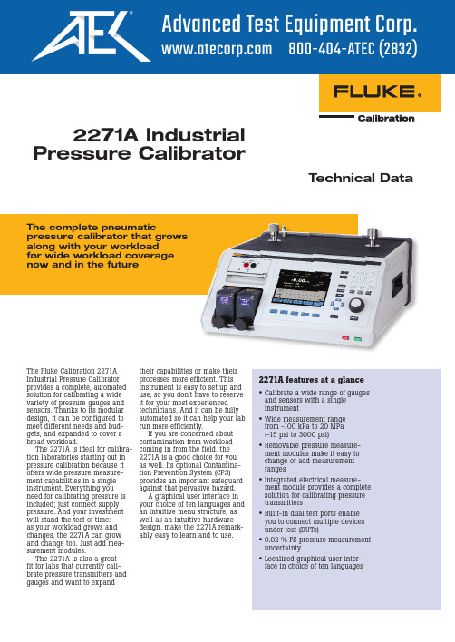
SP2271数字超高频毫伏表频率计使用说明书..
高频仪使用指南

高频仪使用指南高频仪是一种常见的电子设备,用于检测和测量高频信号的特性。
在本篇文章中,将为您详细介绍高频仪的使用方法和技巧,以帮助您更好地利用高频仪进行工作或学习。
一、了解高频仪在正式开始使用高频仪之前,首先需要了解高频仪的基本结构和工作原理。
高频仪通常由频谱分析仪、信号发生器和某些附件组成。
频谱分析仪用于测量和分析信号的频率、幅度和相位等特性;信号发生器用于产生不同频率、幅度和相位的信号。
二、操作前的准备在开始操作高频仪之前,需要进行以下准备工作:1. 选择合适的工作环境:高频仪对工作环境的要求较高,应选择尽可能无电磁干扰和较低噪声的地方进行操作。
2. 检查设备连接:确保高频仪的各个部分正确连接,如信号源和频谱分析仪之间的连接线。
3. 电源和保护措施:确认高频仪的电源已接好,并设置好相应的电流保护措施,以防止设备受损。
三、使用步骤以下是使用高频仪的基本步骤:1. 打开电源:首先,将高频仪的电源打开,并等待设备启动。
在此过程中,请不要进行任何操作,以免干扰设备正常启动。
2. 设置信号源:根据实际需要,设置信号源的频率、幅度和相位等参数。
可以通过设备上的按钮或旋钮进行设置,并在显示屏上确认所设置的参数。
3. 连接信号源与频谱分析仪:使用合适的连接线将信号源与频谱分析仪连接起来,确保连接牢固且没有松动。
4. 启动频谱分析仪:打开频谱分析仪,并根据实际需要设置相关参数,如中心频率、带宽和参考电平等。
5. 监测信号:开始监测所需的信号,并观察频谱分析仪上的显示结果。
可以通过调整信号源的参数来调整和优化信号的特性。
6. 数据分析:根据频谱分析仪上显示的信号特性进行数据分析。
可以测量和记录频率、幅度、相位差等数据,以便后续的分析和处理。
四、技巧与注意事项在使用高频仪时,以下是一些技巧和注意事项,以帮助您更好地应对各种情况:1. 熟悉设备手册:在使用高频仪之前,先阅读并熟悉设备的用户手册,了解设备的各种功能和设置。
Fluke Calibration 2271A工业压力计ibrator说明书

2271A Industrial Pressure CalibratorTechnical DataThe complete pneumaticpressure calibrator that grows along with your workload for wide workload coverage now and in the futureThe Fluke Calibration 2271A Industrial Pressure Calibrator provides a complete, automated solution for calibrating a wide variety of pressure gauges and sensors. Thanks to its modular design, it can be configured to meet different needs and bud-gets, and expanded to cover a broad workload.The 2271A is ideal for calibra-tion laboratories starting out in pressure calibration because it offers wide pressure measure-ment capabilities in a single instrument. Everything you need for calibrating pressure is included; just connect supply pressure. And your investment will stand the test of time: as your workload grows and changes, the 2271A can grow and change too. Just add mea-surement modules.The 2271A is also a great fit for labs that currently cali-brate pressure transmitters and gauges and want to expand2271A features at a glance•Calibrate a wide range of gauges and sensors with a single instrument•Wide measurement range from -100 kPa to 20 MPa (-15 psi to 3000 psi)•Removable pressure measure-ment modules make it easy to change or add measurement ranges•Integrated electrical measure-ment module provides a complete solution for calibrating pressure transmitters•Built-in dual test ports enable you to connect multiple devices under test (DUTs)•0.02 % FS pressure measurement uncertainty•Localized graphical user inter-face in choice of ten languagestheir capabilities or make their processes more efficient. This instrument is easy to set up and use, so you don’t have to reserve it for your most experienced technicians. And it can be fully automated so it can help your lab run more efficiently.If you are concerned about contamination from workload coming in from the field, the 2271A is a good choice for you as well. Its optional Contamina-tion Prevention System (CPS) provides an important safeguard against that pervasive hazard.A graphical user interface in your choice of ten languages and an intuitive menu structure, as well as an intuitive hardware design, make the 2271A remark-ably easy to learn and to use.1T hese external drivers are 24 V dc outputs that operate accessories such as the Contamination Prevention System2U SB port3E thernet connector4R S-232 connector5M aster on/off switch6L ine power fuse AC PWR INPUT Connector7A ll of the pressure connections are madeon the rear panel through this replaceable manifold8G raphical user interface in choice of ten languages features an easy-to-read, intuitive menu structure that lets you access any feature within four button presses or less 9T he large main display enables you to easily view and edit important information10R eal time graph makes it easy to see pressure stability or procedure status11F unction softkeys12P ush the Setpoint button to quickly enter a pressure value to control13P ressure measurement modules snap in and out easily14T est ports provide easy, hand-tightconnection to devices under test15R eference port for applications that require an atmospheric reference16 Handle17M ake minor adjustments to the pressure using the jog wheel; ideal for calibration of analog dial gauges1234567108914151416171112132 Fluke Corporation 2271A Industrial Pressure CalibratorVersatile pressure measurement modules The 2271A uses PM200 Pressure Measurement Modules. These modules use a highly character-ized silicon pressure sensor to provide an economical method of making accurate pressure measurements. The 0.02 % full scale (FS) specification includes the short-term performance of the module (linearity, hysteresis and repeatability) as well asits long-term stability and the uncertainty of the calibration standard. Users can be confi-dent in the PM200 measurement performance.Install up to two pressure modules in the 2271A chassis at one time, mixing and match-ing module ranges to get the combination that best suits your needs. There is no limit to the number of modules that can be used with the system, allowing you to change pressure ranges on the fly to meet your needs. Modules snap in and out quickly and easily through the front of the 2271A; just slide each into a specially-designed track and tighten the knob until you hear it click into place. The click tells you the module is safelyin place; a special anti-torque guard on the knob prevents over-tightening so you never have to wonder if you tightened it too much or not enough. Each module uses an enhanced face-seal design that has been leak tested to pres-sures three times higher than the maximum working pressure. You don’t have to worry about a leak in the system affecting your ability to measure and control pressure.Wide workload coverage for the present and the futureThe 2271A features pres-sure ranges from -100 kPa to20 MPa (-15 psi to 3000 psi), which covers the requirements of a wide range of gauges and sensors. Thanks to its modular design, the 2271A enables you to install two modules with different measurement ranges within the same chassis. You can purchase modules to match your current workload now; later, when your workload changes and grows, you can easily add ranges. This flexibility enables you to maintain your investment in the 2271A for years to come.A built-in electrical measure-ment module (EMM) with HARTcapabilities enables you to per-form closed loop, fully automated calibration on 4-20 mA devices such as smart transmitters, gauges and switches. Just set up the 2271A and then walk away to attend to other tasks.The EMM supplies 24 V dc loop power for measuring mA and V dc. It has a built-in 250 Ohm resistor that can be toggled on or off, eliminating the need to have an external resistor to enable HART communications. The 2271A accuracy specifi-cations are provided in full and supported by a technical note that details its measurement uncertainty so you know exactly what you are getting. This technical note is available for download on the website. As with all Fluke Calibration instruments, these specifications are conservative, complete and dependable.Use the 2271A to perform closed loop, fully automated calibration on4-20 mA devices like this transmitter.Install up to two pressuremodules in the 2271Achassis at one time.3 Fluke Corporation 2271A Industrial Pressure CalibratorDual test ports on top of the 2271A let you easily mount two devices under test.Conveniently located dual test ports and reference portDual test ports on the top of the 2271A let you easily mount two devices under test (DUTs). You can potentially double your throughput without spending time searching for fittings and tees. The vertical test ports let you easily connect analog dial gauges without the need for additional test stands or mani-folds. Two test port types are supported, the standard HC20 or the P3000 test port. Both types of test ports enable you to make hand tight connections to traditional NPT, BSP, or metric pressure fittings. The HC20 test port includes easy grip features and integral support for M20connections, whereas the P3000style test port provides back-wards compatibility for users ofFluke Calibration P3000 dead-weight testers or P5500 pressurecomparators.A reference port is alsolocated on top of the 2271A forapplications that require anatmospheric reference.Safety features protectoperators and instrumentsEach measurement module, aswell as the main chassis, haspressure relief valves to protectthe instrument and its operatorsfrom accidental overpressure.The 2271A has been designedusing Sound Engineering Prac-tices (SEP). With the internalrelief valves, user-settable pres-sure limits, and emergency abortbutton, safety is the highestpriority.Preventing contaminationIf your workload includes devicesthat contain different substanceslike water, oil and gas, youcould be at risk for contamina-tion—something getting into yoursystem that isn’t supposed to bethere. Contamination can cloga calibrator’s valves, wear outits parts, and make it difficult tomaintain pressure. If the con-tamination gets into the sensor,it can actually change the cali-brator’s behavior and throw offyour readings. If contaminationis a concern to you, order theoptional Contamination Preven-tion System (CPS) to help keepthe calibrator’s valves clean andfree from debris.The CPS provides an unprec-edented level of protection bymaintaining uni-directionalflow away from the controller, agravity sump system, and a two-stage filtering system.The Contamination Prevention System helps keep the valves on the 2271A cleanand free from debris.4 Fluke Calibration 2271A Industrial Pressure CalibratorAutomation, support and trainingAutomate with COMPASS®software for improved con-sistency and throughput Fluke Calibration COMPASS for Pressure software is designed specifically for pressure calibra-tion. It enables you to automate the 2271A and run complete pressure calibration sequences on single or multiple devices under test. COMPASS software removes the unknowns often associated with getting auto-mated systems online. The 2271A also features a full remote interface that enables you to use it with custom software or other data acquisition equip-ment. Details about the interface are provided in the 2271A User Manual.CarePlans help you manage cost of ownershipReduce downtime and control your cost of ownership with a CarePlan. Fluke Calibration offers one-year, three-year and five-year Priority Gold CarePlans, which feature an annual stan-dard or accredited calibrationof your 6270A calibrator with guaranteed six-day in-house turnaround, plus free repairs with guaranteed ten-dayin-house repair (includes cali-bration). One-year, three-year, and five-year Silver CarePlans are available for those customers who only want extended war-ranty coverage.A range of training optionsgets you up and runningquicklyWe sponsor pressure and flowcalibration courses in our Phoe-nix, Arizona facility in the UnitedStates. We also host periodicweb seminars at no charge on awide variety of pressure calibra-tion topics. If you need serviceor maintenance training to helpyou maintain your fleet of pres-sure controllers, we can help youthere, too.We’re here to helpFluke Calibration’s testing, repairand calibration services arededicated to filling your needsquickly and at a fair cost whilemaintaining the unmatched levelof quality that is our trademark.Our pressure calibration labo-ratories are accredited by theAmerican Association for Labo-ratory Accreditation (A2LA) forconformance to ISO Guide 17025.We maintain global calibrationand repair facilities to help youkeep your hardware in top work-ing order.Gold CarePlans Silver CarePlansAnnual calibration Extended warranty coveragebeyond original factory warrantyFree repairs with guaranteed Calibration included on repairPre-paid priority freight on return Free product updates performed attime of repairInstrument CarePlanInstrument CarePlanWe sponsor pressure and flow calibration courses inour Phoenix, Arizona facility.5 Fluke Calibration 2271A Industrial Pressure CalibratorSummary specificationsSupply pressure requirementsClean dry air or nitrogen (industrial grade, 99.5 %)Maximum particulate contamination≤ 1.25 micrometer (50 microinches)Maximum moisture content-50 °C dew pointMaximum hydrocarbon content30 ppmInterface / communicationsPrimary remote interfaces Ethernet, RS-232, USBElectrical Measurement Module (EMM)Connection Standard 4 mm jackMaximum 30 V dc w.r.t. chassis groundAux drivers 4 external solenoid drivers24 V dc. 100 % duty cycle when turned, reducing to 40 % shortly after.6 Fluke Calibration 2271A Industrial Pressure CalibratorPressure measurement specificationsNotes•G auge mode modules (PM200-GXXX or PM200-BGXXX) with ranges of 100 kPa (15 psi) or greater will support absolute mode measurement when used with a Barometric Reference Module.•F or temperatures from 15 °C to 18 °C and 28 °C to 35 °C, add 0.003 % FS/°C.•U ncertainty for gauge mode modules assumes routine zeroing. Uncertainty for absolute-mode modules includes 1-year zero stability.This specification can be reduced to 0.05 % FS if the PM200 module is zeroed on a continuing basis to remove the 1-year zero stability component.•I nstrumental measurement uncertainty for gauge mode modules used in absolute mode by addition of a barometric reference module iscalculated as the uncertainty of the gauge mode module plus the uncertainty of the Barometric Reference Module.7 Fluke Calibration 2271A Industrial Pressure Calibrator8 Fluke Corporation 2271A Industrial Pressure CalibratorFluke Calibration PO Box 9090,Everett, WA 98206 U.S.A.Fluke Europe B.V.PO Box 1186, 5602 BD Eindhoven, The NetherlandsWeb access: http://www.flukecal.euFor more information call:In the U.S.A. (877) 355-3225 or Fax (425) 446-5716In Europe/M-East/Africa +31 (0) 40 2675 200 or Fax +31 (0) 40 2675 222 In Canada (800)-36-FLUKE or Fax (905) 890-6866From other countries +1 (425) 446-6110 or Fax +1 (425) 446-5716 Web access: ©2016 Fluke Calibration. Specifications subject to change without notice. Printed in U.S.A. 3/2016 6007367a-enModification of this document is not permitted without written permission from Fluke Calibration.Fluke Calibration. Precision, performance, confidence.™Ordering informationModelsDescription2271A-NPT-HC20Industrial Pressure Calibrator Chassis, NPT Manifold, HC20 Test Port Connections 2271A-NPT-P3K Industrial Pressure Calibrator Chassis, NPT Manifold, P3000 Test Port Connections 2271A-BSP-HC20Industrial Pressure Calibrator Chassis, BSP Manifold, HC20 Test Port Connections 2271A-BSP-P3KIndustrial Pressure Calibrator Chassis, BSP Manifold, P3000 Test Port ConnectionsPressure modulesPlease refer to the summary specifications for details about the pressure measurement modules.Accessories CASE-2271Shipping Case, 2271ACASE-PMM Shipping Case, 3 PMM ModulesPK-2271-NPT-HC20Lines and Fittings Kit, 2271A-NPT-HC20PK-2271-NPT-P3K Lines and Fittings Kit, 2271A-NPT-P3K PK-2271-BSP-HC20Lines and Fittings Kit, 2271A-BSP-HC20PK-2271-BSP-P3K Lines and Fittings Kit, 2271A-BSP-P3K PMM-CAL-KIT-20M Pressure Module Calibration Kit, 20 MPa (3000 psi)VA-PPC/MPC-REF-110Vacuum Pump Package, 110 V VA-PPC/MPC-REF-220Vacuum Pump Package, 220 VThe broadest range of calibration solutionsFluke Calibration provides the broadest range of cali-brators and standards, software, service, support and training in electrical, temperature, pressure, RF and flow calibration.Visit for more information aboutFluke Calibration products and services.The Contamination Prevention System acts as a test stand for connecting units under test, as well as for preventing contamination from reaching the 2271A.。
交流毫伏表使用说明

交流毫伏表使用说明SG2171交流毫伏表使用说明与LM2100系列交流毫伏表使用说明一、使用特征1.1 测量精度高,频率特性好5Hz~2MHz1.2 测量电压范围广:(30uV~100V)二、技术指标2.1通道:单2.2表头指针:黑色指示通道的值2.3刻度值:正弦波有效值1V=0dB值,1mW=0dBm值2.4电压量程:12级,300uV~100V2.5分贝量程:-70dB~+40 dB2.6电压误差:1KHz为基准,满度≤±3%2.7频率响应:20Hz~200KHz,≤±3%5Hz~20Hz,200KHz~2MHz,≤±10%2.8输入阻抗:1MΩ2.9输入容抗:50PF2.10最大输入电压DC+ACp-p:300V,300uV~1V量程500V,3V~100V量程2.11输出电压:0.1V ±10%,1KHz2.12输出电压频响:5 Hz~2MHz,±3%参照1KHz无负载2.13电源电压:~200V,50Hz三、使用注意事项3.1不可将物体放置在交流毫伏表上,注意不要堵塞仪器通风孔。
3.2仪器不可遭到强烈的撞击。
3.3不可将导线或针插进通风孔。
3.4不可将烙铁放在仪器框架或表面。
3.5不可将磁铁靠近表头。
3.6使用之前的检查步骤:3.6.1检查表针:检查表针是否指在机械零点,如有偏差,请将其调至机械零点。
3.6.2检查量程旋钮是否指在最大量程处,如有偏差,请将其调至最大量程处。
3.6.3检查电压,在接通电源之前应检查电源电压。
3.7操作注意:输入电压不可高于规定的最大输入电压四、面板操作键作用说明(以下4.1~4..6对应附图(1)~(6))4.1电源开关将电源开关按键弹出即为“关”位置,将电源线接入,按电源开关,以接通电源。
4.2显示窗口:表头指示输入信号的幅度。
对于SG2172,黑色指针指示。
4.3零点调节:开机前,如表头指针不在机械零点处,请将其调节至零点。
频率计的使用教程

频率计的使用教程频率计是一种常见的电子测量仪器,它主要用来测量电波的频率。
在电子领域中,频率是一个关键的参数,对于各种电子设备和电路的设计、调试以及故障排除都起到非常重要的作用。
本文将介绍频率计的基本原理和使用方法,以帮助读者更好地使用这一仪器。
1. 频率计的原理频率计基于时间测量的原理工作。
它通过计时器测量电波的一个周期所需要的时间,并将其转化为频率。
主要有两种类型的频率计:直接计数频率计和间接计数频率计。
直接计数频率计通过计算固定时间内电波周期数的方式来测量频率。
它具有精确度高的优点,但需要较长的测量时间。
间接计数频率计则通过测量时间基准中的计数周期数来估算电波的频率。
它具有测量速度快的优点,但精确度相对较低。
2. 频率计的使用步骤使用频率计之前,我们需要确保仪器正常工作,并将其连接到要测量的电路或设备上。
第一步是设置测量范围,一般频率计会提供多个测量范围可供选择。
我们需要根据待测电波的频率范围选择合适的测量范围,以保证测量结果的准确性。
第二步是调整频率计的灵敏度,也称为量程档位。
灵敏度设置过高会导致测量结果不准确,而设置过低则可能无法检测到待测信号。
通常,我们可以根据实际情况进行适当的灵敏度调整。
第三步是连接待测信号源到频率计的输入端。
我们需要确保信号源的输出与频率计的输入匹配,并使用合适的连接线杜绝信号干扰或衰减。
第四步是启动频率计,并等待一段时间以达到稳定状态。
这个时间可以根据仪器的规格和信号源的稳定性来确定。
第五步是开始测量,根据仪器的操作界面,可以选择不同的测量模式进行频率测量。
一般来说,频率计会提供多种显示方式,如数字显示和图形显示等。
3. 注意事项在使用频率计时,我们需要注意以下几点:首先,要保持仪器的环境干燥、清洁,并避免剧烈震动或碰撞,以确保仪器正常工作。
其次,需要根据仪器的规格和测量要求选择合适的频率计。
不同的频率计有不同的测量范围、精确度和测量速度。
此外,还需要注意待测信号的特性,如频率范围、幅值、稳定性等。
频率计的使用方法

频率计的使用方法
使用频率计的步骤:
1. 接通电源:将频率计插入电源插座,打开电源开关;
2. 连接信号源:将待测信号源的输出信号连接至频率计的输入端口,注意输入的信号的正负极性需正确连接;
3. 调整输入信号的幅度:调节信号源的输出幅度,使其在频率计的量程内,并不超过频率计的测量限制;
4. 选择测量范围:选择合适的测量范围,可通过旋转测量范围选择手柄可切换不同数字范围;
5. 选择测量精度:在需要高精度和低精度之间选择,可通过旋转测量范围选择手柄切换;
6. 开始测量:按下“Start”键开始测量,频率计会在屏幕上显示出测量结果。
若需多次观测,则需重复以上步骤。
7. 关闭频率计:在使用完频率计后,先将信号源关闭,再关闭频率计电源。
注意事项:
1. 频率计的工作电压与信号源输出的电压需匹配,以避免损坏测量电路;
2. 输入信号的幅度不要超过频率计的量程,在高幅度输入信号时,可选择合适的衰减器来降低信号幅度;
3. 测量结果应准确,避免因地面干扰、放电等外界因素干扰产生误差;
4. 在使用过程中,避免将频率计与其他强干扰源放置太近,避免干扰发生。
数显频率表使用说明书

数显频率表使用说明书
数显频率表是一种用来测量电流频率的仪器,通过显示屏上的数字来显示电流的频率。
下面是数显频率表的使用说明书:
1. 连接电源:将数显频率表的电源线插入电源插座,并确保电源稳定。
2. 连接测试电路:将测试电路的电流引线分别连接到数显频率表的输入端口。
确保连接正确,避免反接。
3. 打开电源:打开数显频率表的电源开关,仪器将开始运行。
4. 设置量程:根据需要测量的电流频率范围,调节数显频率表的量程。
通常有自动量程和手动量程两种模式可选择。
5. 选择显示模式:数显频率表通常有不同的显示模式,如实时显示、最大值显示、最小值显示等。
根据需要选择相应的显示模式。
6. 进行测量:将待测电流接入测试电路后,数显频率表将自动测量并显示电流的频率值。
观察显示屏上的数字,即可得到电流的频率。
7. 记录结果:将测量得到的频率值记录下来,并根据需要进行进一步的分析和处理。
8. 关闭电源:测量完成后,及时关闭数显频率表的电源开关,并拔掉电源线。
注意事项:
- 使用数显频率表时要注意电流的极性,确保连接正确。
- 在测量过程中要保持稳定,避免外界干扰。
- 如果频率过高,可能需要额外的保护措施,如使用电流传感器等。
交流毫伏表的使用方法

交流毫伏表的使用方法
毫伏表是一种用来测量电路中电压的仪器,通常用于电子电路的调试和故障排查。
以下是毫伏表的使用方法:
1.首先,将毫伏表的选择旋钮(通常在表头或底部)设置为“毫伏”档位。
2.接下来,将红色测量线夹在待测电路的正极点上,将黑色测量线夹在负极点上。
3.打开电路,让电流流过毫伏表,记录读数。
如果电路中没有电流流动,则读数为零。
4.如果需要测量直流电源的电压,可以选择直流电压(DCV)档位,重复步骤2和3。
5.如果需要测量交流电源的电压,可以选择交流电压(ACV)档位,重复步骤2和3。
6.在使用过程中,需要注意毫伏表的量程范围,避免超过表的极限值。
7.在测量结束后,需要将毫伏表选择旋钮调回“关”档位,避免浪费电池和损坏表头。
需要注意的是,毫伏表操作需要谨慎,避免短路或其他意外情况发生,同时需要使用适当的保护设备和工具,确保自身安全和电路正常运行。
数字频率计说明书

课程设计说明书学生:XX 学号:学院: xx学院班级: XX班题目: 数字频率计指导教师:职称:2012年1月6日容摘要在数字电路中,数字频率计属于时序电路,它主要由具有记忆功能的触发器构成。
在计算机及各种数字仪表中,都得到了广泛的应用。
在CMOS电路系列产品中,数字频率计使用量最大、品种最多产品,是计算机、通讯设备等科研领域不可缺少的测量仪器,频率是最最基本的参数之一,并且与许多电参量的测量方案、测量结果都是有十分密切的关系,因此频率的测量就显得更为重要。
测量频率的方法有多种,其中电子技术器测量频率具有精度高、使用方便、测量迅速,以及便于实现测量过程自动化的优点,是频率测量手段之一。
常用的测量方法有测频法、测周法、侧周期/频率。
本文阐述了用测频法构成的数字频率计。
关键字:频率数字频率计单稳态1 课程设计题目数字频率计设计2 课程设计任务与要求2.1 数字频率计的基本原理数字频率计的主要功能是测量周期信号的频率。
频率是单位时间(1s)信号发生周期变化的次数。
如果我们能在给定的1s时间对信号波形计数,并将计数结果显示出来,就能读取被测信号的频率。
数字频率计首先必须获得相对稳定与准确的时间,同时将被测信号转换成幅度与波形均能被数字电路是别的脉冲信号,然后通过计数器计算这一段时间间隔的脉冲个数,将其换算后显示出来。
2.2 技术指标如下:(1).数字显示功能:用数码管显示测量信号(2).测量围: 10Hz~100kHz(3).测量精度:误差不超过1%(4).显示方式: 6位LED数码(5).系统框图3 方案选择与论证频率计是用来测量正弦信号、矩形信号、三角形信号等波形工作频率的,根据频率的概念是单位时间里脉冲的个数,要测被测波形的频率,则需要测被测波形在1s里有多少个脉冲,所以,如果用一个定时是1S控制一个闸门电路,在1S闸门打开,让被测信号通过而进入计数器电路,即是被测信号的频率。
任务要求分析:频率计的测量围要10Hz~100kHz,且精度为10Hz,所以要用6片10进制计数器构成100000进制对输入的被测脉冲进行计数;要求输入信号的幅值为20mv~5v,所以要经过衰减与放大电路进行检查被测脉冲的幅值;由于被测的波形是各种不同的波,而后面闸门或计数电路要求被侧的信号必须是矩形波,所以还需要波形整形电路;频率计的输出显示要经过锁存器进行稳定在通过6位LED数码管进行显示。
- 1、下载文档前请自行甄别文档内容的完整性,平台不提供额外的编辑、内容补充、找答案等附加服务。
- 2、"仅部分预览"的文档,不可在线预览部分如存在完整性等问题,可反馈申请退款(可完整预览的文档不适用该条件!)。
- 3、如文档侵犯您的权益,请联系客服反馈,我们会尽快为您处理(人工客服工作时间:9:00-18:30)。
目录第一章概述1第二章工作特性 22.1 毫伏表 22.2 频率计 32.3 基准输出 32.4 远控功能 32.5 其它 4 第三章面板说明 53.1 前面板 53.2 后面板10 第四章使用说明114.1 测量前的工作114.2 电压输入通道测量124.3 系统设置14 第五章远程控制175.1 遥控操作前的准备工作175.2 命令格式说明185.3 命令简介195.4 命令详解20 第六章注意事项24 第七章附件清单26SP2271是一种新型的采用微处理器控制的智能化数字超高频毫伏表/频率计,该仪器采用检波放大工作原理,能测量10kHz~1000MHz 的正弦电压。
测量电压范围800µVrms~10Vrms、分辨率1μV、准确度优于±2%。
本仪器采用高亮度VFD显示,读数清晰、亮度高、寿命长,该机具有频率响应良好、驻波系数小、灵敏度高、功耗低、体积小、重量轻等特点。
仪器能自动调零,测量电压时既可以选择自动量程也可以选择手动测量量程,仪器带有RS232接口,可进行远程测量控制。
该仪器是生产车间和实验室超高频电压计量测试的必备仪器(如超高频标准信号源输出电压频响的计量测试)。
该仪器测量的稳定性好、分辨率高、重复性好,可用于计量信号源输出电压的误差和稳定性,同时也能用于10kHz到1GHz超高频电压计量工作传递标准,也可用于自动测试系统中测试高频电压。
该仪器可选配10kHz~1000MHz频率插件,使该机一机两用,可作为10kHz~1000MHz频率计使用。
该仪器按GB6587.1-86“电子测量仪器环境试验总纲”的规定属于第Ⅱ组仪器。
(额定使用上限温度试验按SJ2314-83的3.15规定湿度为80%)。
2.1 毫伏表2.1.1测量电压的频率范围:射频探头10kHz~1000MHz2.1.2测量电压的范围:800uVrms~10Vrms,50Ω负载2.1.3电压测量方式:手动或自动2.1.4电压测量量程档为:4mVrms/40mVrms/400mVrms/4Vrms/10Vrms 2.1.5测量100kHz电压的工作误差:(0~40℃)注: 1 标准电压源的频率100kHz2 波形要求:正弦波,失真度≤0.3%,幅度误差≤±0.3%;2.1.6测量电压的频率响应误差(100kHz为基准,50Ω同轴终端精密负载)2.1.7射频探头插入50Ω同轴三通(50Ω负载)10kHz~200MHz ,VSWR ≤ 1.35。
2.1.7.1 输入阻抗:≥100kΩ2.1.7.2 输入电压:≤3pF2.1.8电压表的射频探头测量交流电压不允许超过15Vrms,V DC<50V。
2.2 频率计(选配件)2.2.1 频率测量范围:10kHz ~ 2GHz2.2.2 输入特性:最小输入电压:50mVrms最大允许输入电压:5Vp-p输入阻抗:R>500kΩ c<30pF (f ≤ 50MHz)R>50Ω (f > 50MHz)耦合方式:AC波形适应性:正弦波低通滤波器:截止频率约100kHz带内衰减:≤ 3dB带外衰减:≥ 30dB2.2.3测量时间:100ms、1s选择2.2.4显示位数:六位(Gate=100ms)七位(Gate=1s)2.2.5时基:优于5×10⁻⁵(22℃±5℃)2.2.6测量误差:时基误差±触发误差(信噪比优于40dB时触发误差小于3‰)2.3 基准输出2.3.1 输出频率:≈100kHz2.3.2 输出幅度:1Vrms,±5‰2.3.3 输出阻抗:50Ω2.4 远控功能2.4.1 接口:RS2322.4.2 远控功能2.4.2.1 量程选择:手动或自动2.4.2.2 测量速率:快/慢2.4.2.3查询测量结果2.4.2.4自动调零2.4.2.5自动校正2.4.2.6 返回本地2.5 其它2.5.1电源电压为220V±10%,频率为50Hz±5%,功耗约35W。
2.5.2电压表的MTBF符合SJ1889-8“电子测量仪器可靠性试验方案”,平均无故障工作时间MTBF≧2000小时。
2.5.3电压表的安全性能符合GB4793-84“电子测量仪器安全要求”。
2.5.4外形尺寸:255×370×100(mm)2.5.5仪器重量:3.5kg3 面板说明3.1 前面板3.1.1 前面板指示灯介绍3.1.2 按键简介1)自动量程键【自动】按下该键,进入自动量程状态,自动量程指示灯亮。
2)降量程键【▲】按下该键,进入手动量程状态,自动量程指示灯灭。
同时当前量程降一档。
3)升量程键【▼】按下该键,进入手动量程状态,自动量程指示灯灭。
同时当前量程升一档。
4)返回本地键【本地】在远地状态下,“Rmt”标志亮,按下该键,进入本地状态,“Rmt”标志灭。
5)SHIFT键【SHIFT】基本功能:用来和其它键一起实现二次功能。
按下【SHIFT】键后,显示屏右端的“s”标志亮。
再按下其它键后,“s”标志灭。
6)系统键【系统】按下该键,进入系统功能设置状态,此时可以设置通讯接口、RS232波特率、RS232奇偶校验位、蜂鸣器开关状态等。
7)校正键【校正】在电压测量状态下,将基准输出接到电压输入,按下该键,校正电压测量误差。
8)调零键【调零】按下该键,进入调零状态,显示区显示“ZEROING”。
调零结束后,显示区显示电压测量值。
9)电压快速测量键【快】按下该键,进入电压快速测量状态,电压快速测量指示灯亮。
10)电压慢速测量键【慢】按下该键,进入电压慢速测量状态,电压慢速测量指示灯亮。
11)电压通道键【电压】按下该键,仪器测量信号为电压输入通道信号,电压通道指示灯亮。
此时,频率测量的相关按键为无效按键。
12)频率通道键【频率】按下该键,仪器测量信号为频率输入通道信号,频率通道指示灯亮。
此时,电压测量的相关按键为无效按键。
13)高频测量键【频率>50MHz】当被测频率大于50MHz时,按下该键,高频测量指示灯亮,进入高频测量状态,再次按下该键,指示灯灭,取消高频测量状态。
14)低通键【低通100kHz】当被测频率小于100kHz时,按下该键,低通测量指示灯亮,进入低通测量状态,再次按下该键,指示灯灭,关闭低通。
15)闸门100ms键【闸门0.1s】按下该键,频率测量闸门为100ms。
16)闸门1s键【闸门1s】按下该键,频率测量闸门为1s。
17)复位键【复位】按下该键,恢复到开机状态。
18)数字输入键【↑】【↓】【←】【→】【+/-】用来对当前显示的参数进行修改。
19)数据输入确认键【确认】按下该键,当前输入的数据确认并生效。
20)4mV档选择键【4mV】按下该键,电压则测量手动选择到4mV档。
21)40mV档选择键【40mV】按下该键,电压则测量手动选择到40mV档。
22)400mV档选择键【400mV】按下该键,电压则测量手动选择到400mV挡。
23)4V档选择键【4V】按下该键,电压则测量手动选择到4V挡。
24)10V档选择键【10V】按下该键,电压则测量手动选择到10V挡。
3.1.3 显示屏电压测量时显示电压值,频率测量时显示频率值,以及显示必要的提示符。
3.2 后面板介绍1)电源输入2)RS232连接口(标配)4.1测量前的工作4.1.1 测量前的检查先仔细检查电源电压是否符合本仪器的电压工作范围,确认无误后方可将电源线插入本仪器后面板的电源插座内。
仔细检查测试系统电源情况,保证系统接地良好,仪器外壳和所有的外露金属均已接地。
在与其它仪器相联时,各仪器间应无电位差。
电压测量时应将电压输入通道航空插座推入电压测量头的航空插头。
4.1.2 仪器开机开机时,检波探头的输入信号应断开,以保证初始化正常。
按下面板上的电源按钮,电源接通,仪器进入初始化,蜂鸣器先鸣响一声,然后点亮VFD显示屏和LED指示灯,显示仪器型号。
初始化结束后进入电压测量状态,电压输入通道LED亮,自动量程LED 亮。
4.2电压输入通道测量4.2.1 简介仪器测量电压输入通道信号的电压。
如果仪器当前测量信号为电压输入通道信号,则“电压通道指示灯”亮,否则按【电压】键选择测量信号为电压输入通道信号,此时“电压通道指示灯”亮。
4.2.2 调零在进行测量之前,需要对本仪器进行调零,以保证20mVrms以下电压测量的准确性。
调零时,必须先将输入端信号去掉(如果调零时输入端有信号输入,则调零不能完成)。
然后按下【调零】键,进入调零状态,显示屏显示“ZEROING”。
调零结束后,显示调零后的电压值(0.000mVrms)。
注:在测量4mVrms以下的小信号时,最好在屏蔽空间内进行,以保证微小信号测量的准确性。
4.2.3 校正将检波探头信号输入端连接到基准输出,按下【校正】键,系统将自动校正仪器测量偏差。
注:关机或复位不保存校正值4.2.4 量程选择电压输入通道有自动量程有手动量程选择。
本仪器共有五个量程:测量时一般使用自动量程,这样可以保证仪器测量数据的准确。
使用手动量程时,如果输入电压大于当前量程的上限时,测量数据误差较大。
4.2.4.1 自动量程按【自动】键,进入自动量程测量状态,此时自动量程指示灯亮。
自动量程时,仪器自动根据当前电压值换档。
如果当前电压值大于当前量程的上限,则升到上一个量程;如果当前电压值小于当前量程的下限,则降到下一个量程。
4.2.4.2 手动量程按【▲】和【▼】键或者量程选择键,进入手动量程测量状态,此时自动量程指示灯灭,相应的量程档位指示灯亮。
按【▲】键,将当前量程向下降一档;按【▼】键,将当前量程向上升一档。
手动量程时,可以按照需要设置量程。
如果输入电压大于当前量程的上限的275%,则显示输入超载“OVLD”,此时小数点和显示单位不变。
例如:当前量程为400mV档,如果输入电压大于1100.0mV,则显示超载符号“OV.LD mVRMS”,此时小数点位置和显示单位和400mV档量程保持一致。
如果显示超载,为了不损坏仪器,手动时应该向上升一个量程。
手动量程时,可以提高分辨率,也可以提高测量速度,但是如果输入电压大于当前量程的上限时,测量数据误差较大。
4.2.5 测量速率按【快】键,选择“快速”测量;按【慢】键,选择“慢速”测量。
共有两种测量速率,一种为“快速”,一种为“慢速”。
慢速时测量速率为每秒2次,显示4位有效数字。
快速时测量速率为每秒20次,此时显示有效数字只有3位,最后一位始终显示为“o”。
4.3系统设置4.3.1 简介按【系统】键进入系统菜单进行系统参数设置。
可以用【系统】键改变系统功能,也可以用数字设置键的左右键改变系统功能。
系统参数设置后自动存入EEPROM,关机后也不丢失。
