SMC真空压力表 使用手册
SMC GP46-SMY13EN 压力计说明书

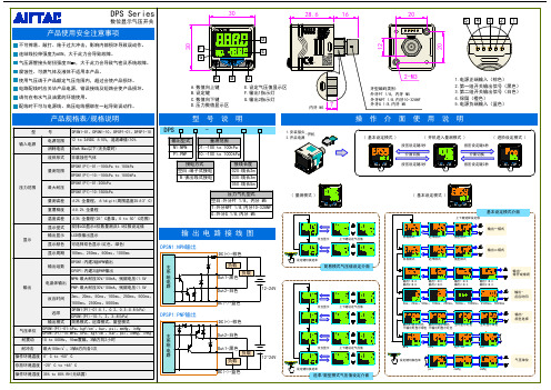
Page 1 of 2Instruction ManualGP46Pressure Gauge with Switchis pneumatic system.1 Safety InstructionsThese safety instructions are intended to prevent hazardous situations and/or equipment damage. These instructions indicate the level of potential hazard with the labels of “Caution,” “Warning” or “Danger.” They are all important notes for safety and must be followed in addition to International Standards (ISO/IEC) *1), and other safety regulations. *1)ISO 4414: Pneumatic fluid power - General rules relating to systems. ISO 4413: Hydraulic fluid power - General rules relating to systems.IEC 60204-1: Safety of machinery - Electrical equipment of machines. (Part 1: General requirements)ISO 10218-1: Manipulating industrial robots -Safety. etc.• Refer to product catalogue, Operation Manual and Handling Precautions for SMC Products for additional information. • Keep this manual in a safe place for future reference.not avoided, will result in death or serious injury.Warning• Always ensure compliance with relevant safety laws and standards.• All work must be carried out in a safe manner by a qualified person in compliance with applicable national regulations.2 Specifications2 Specification - continuedNote 1) When mounting a pressure gauge, use caution not to tighten excessively. Excessive tightening will cause product to be damaged. Use a pipe tape for sealing.Note 2) Water is not an acceptable fluid. When using the other fluids, please consult with SMC for compatibility information concerning corrosion.Note 3) Set value of pressure switch is indicated by pointer (green). This indicates the position from ON to OFF when the pressure drops in the connection between N.O. (white line) and COM (black line). To set the value, turn needle in clockwise position to the correct value. When setting; if desired set position has been passed, turn needle in a counter-clockwise direction back again beyond the desired value and then once again return needle in a clockwise direction stopping at the desired value. Value must be set while needle is traveling in a clockwise direction. Note 4) Make sure to provide a minimum difference of 0.1 MPa between the set pressure and the operating pressure (including the pressure drop). If the difference is smaller, it could lead to improper operation. The working pressure should be the pressure that adds the set needle error (0.03MPa), hysteresis (0.07MPa), and display accuracy of the set pressure value (±0.05MPa). If accuracy is not taken into consideration, the connection between N.O. (white) and COM (black) may not turn on when the pressure rises.Note 5) Maximum error value: Add the pressure gauge indicator error of 0.03 MPa to the setting needle error.Note 6) Avoid freezing as this may cause a malfunction.Note 7) The guaranteed temperature range for accuracy is 23°C ±5°C.WarningSpecial products might have specifications different from those shown in this section. Contact SMC for specific drawings.3 Installation3.1 InstallationWarning• Do not install the product unless the safety instructions have been readand understood.• Do not apply pressure over the max. value of the scale as it will lead to operation failure.• The maximum frequency of use is 6 times/minute.If there is a pulsation of pressure, it will break in a short period of time.3.2 SelectionCaution• Make sure that no direct impact or vibrations are applied to the body. • Do not apply high load voltage (current) or surge current as this can cause the switch to malfunction. 3.3 MountingCaution• During transport and installation, do not apply shock to the product, such as by dropping doing so will affect its precision.• Regarding the installation posture, place it perpendicular to the ground, with the zero point on the reading of a pressure gauge facing down. • Do not install it in an area that is exposed to high temperature or humidity, because doing so will lead to improper operation.• To screw in the pressure gauge, make sure to turn the gauge by placing a wrench over the square wrench flats. If the pressure gauge is screwed in by holding it on some other area, air leakage or damage may result. 3.4 EnvironmentWarning• Do not use in an environment where corrosive gases, chemicals, salt water or steam are present.• Do not install in an environment of high humidity. • Do not use in an explosive atmosphere.• Do not expose to direct sunlight. Use a suitable protective cover.• Do not install in a location subject to vibration or impact in excess of the product’s specifications .• Do not mount in a location exposed to radiant heat that would result in temperatures in excess of the product’s specifications.3 Installation - continued3.5 PipingCaution• Before connecting piping make sure to clean up chips, cutting oil, dust etc.• When installing piping or fittings, ensure sealant material does not enter inside the port. When using seal tape, leave 1.5 - 2 threads exposed on the end of the pipe/fitting.3.6 LubricationCaution• SMC products have been lubricated for life at manufacture, and do not require lubrication in service.• If a lubricant is used in the system, refer to catalogue for details. 3.7 Circuit Diagram Without indicator lightWith indicator lightThe arrow in the diagram indicates the direction of the pressure increase. The light turns OFF when the pressure becomes higher than the set pressure and turns ON when the pressure becomes lower than the set pressure.4 Settings4..1 Procedure for Setting the Limit Gauge Indicator4.1.1. Before setting the (green) limit indicator, turn the cover counter clockwise (approximately 6 to 7 mm) until it stops. Then, remove by pulling it towards you.4.1.2. Use a flat head screwdriver (with a 2.9 mm blade width) to set the (green) limit indicator. Be careful not to bend the other needle or damage the dial plate.4.1.3. After completing the setting, replace the cover. Fit the cover by aligning the cut out in the cover to the groove on the top of the black case. Turn the cover clockwise (approximately 6 to 7 mm) until it stops. Make sure that the matching mark on the cover is aligned with the groove on the top of the case.4.2 Procedure for Setting the Limit Gauge Indicator (Color Zone Type)4.2.1. Before setting the color zone (red), turn the cover counter clockwise (approximately 6 to 7 mm) until it stops. Then remove by pulling it towards you.4.2.2. Use a pen tip to set the color zone (red). Be careful not to bend the other needle or damage the dial plate.ORIGINAL INSTRUCTIONSRefer to Declaration of Conformity for relevant Directives[option]4.2.3. After completing the setting, replace the cover. Fit the cover by aligning the cut out in the cover to the groove on the top of the black case. Turn the cover clockwise (approximately 6 to 7 mm) until it stops. Make sure that the matching mark on the cover is aligned with the groove on the top of the case.4.3 Procedure for Setting the Limit Gauge Indicator and the Setting Needle4.3.1. Before setting the limit indicator and the (green) setting needle, turn the cover counterclockwise (approximately 6 to 7 mm) until it stops. Then, remove by pulling it towards you.4.3.2. Use a flat head screwdriver (with a 2.9 mm blade width) to set the (green) limit indicator. Be careful not to bend the other needle or damage the dial plate.4.3.3. Before setting the setting needle, use a flat head screwdriver (witha 2.9 mm blade width) to turn the setting screw and set the setting needle to the set pressure.4.3.4. After completing the setting, replace the cover. Fit the cover by aligning the cut out in the cover to the groove on the top of the black case. Turn the cover clockwise (approximately 6 to 7 mm) until it stops. Make sure that the matching mark on the cover is aligned with the groove on the top of the case. 4.4 Procedure for Assembling the Cover Ring Assembly •Pressure gauge for general purpose•Pressure gauge with switch1. Remove the small screw (1 position) from the pressure gauge.2. Place the cover ring on the pressure gauge.3. Using the small screw that is provided with the cover ring, install the cover ring. The installation torque is 0.6 to 0.7 N・m. However, when reassembling, it shall be 0.5 to 0.6 N・m.5 How to OrderRefer to drawings or catalogue for ‘How to Order’.6 Outline Dimensions (mm)Refer to drawings or catalogue for outline dimensions.7 Maintenance7.1 General MaintenanceCaution•Not following proper maintenance procedures could cause the productto malfunction and lead to equipment damage.•If handled improperly, compressed air can be dangerous.•Maintenance of pneumaticsystems should be performedonly byqualified personnel.•Before performing maintenance, turn off the power supply and be sureto cutoff the supply pressure. Confirm that the air is released toatmosphere.•After installation and maintenance, apply operating pressure andpower to the equipment and perform appropriate functional andleakage tests to make sure the equipment is installed correctly.•If any electrical connections are disturbed during maintenance, ensurethey are reconnected correctly, and safety checks are carried out asrequired to ensure continued compliance with applicable nationalregulations.•Do not make any modification to the product.•Do not disassemble the product, unless required by installation ormaintenance instructions.8 Limitations of Use8.1 Limited warranty and Disclaimer/Compliance RequirementsRefer to Handling Precautions for SMC Products.9 Product disposalThis product should not be disposed of as municipal waste. Check yourlocal regulations and guidelines to dispose this product correctly, in orderto reduce the impact on human health and the environment.10 ContactsRefer to or www.smc.eu for contacts.URL : http// (Global) http// www.smc.eu (Europe)'SMC Corporation, Akihabara UDX15F, 4-14-1, Sotokanda, Chiyoda-ku, Tokyo 1010021Specifications are subject to change without prior notice from the manufacturer.© 2020 SMC Corporation All Rights Reserved.Template DKP50047-F-085JPage 2 of 2。
F-SPSA-C01 TCP真空压力表说明书

F-SPSA-C01 TCP真空压力表说明书1.商品名称:F-SPSA-C01 TCP真空压力表。
2.商品毛重:0.85kg。
3.物理测量:压力表。
4.表盘直径:100mm。
5.螺纹:M20*1.5(特殊规格可定制)。
6.材质:外壳镀铭铁,机芯、接头黄铜,内充油。
7.测量范围:-0.1-0.9MPA。
8.精度等级:1.6级。
9.控制方式:两位式缓行结点。
10.安装方式:径向。
11.重量:约800克。
12.F-SPSA-C01 TCP真空压力表使用环境条件:-5~55℃,相对湿度不大于85%;震动频率不大于25HZ,震幅不大于1mm。
13.温度影响:使用温度偏离20±5℃时,不大于4%/10℃。
14.F-SPSA-C01 TCP真空压力表接头的配备:压力表的接头大小根据表盘大小的不同而不同,一般的话表径40的接头是M10*1,表径50和60的是M14*1.5,表径100和150的是M20*1.5。
15.F-SPSA-C01 TCP真空压力表材质的选择:压力表的材质分为三种:1.一般压力表,铁壳、铜机芯、铜接头。
2.外壳不锈钢压力表,不锈钢壳、铜机芯、钢接头。
3.全不锈钢压力表,不锈钢壳、机芯和接头。
16.F-SPSA-C01 TCP真空压力表抗震情况选择:压力表根据抗震能力的不同分为一般压力表和耐震压力表,耐震压力表表内有充灌阻尼油(甘油和硅油)和配套缓冲装置。
17.F-SPSA-C01 TCP真空压力表安装方向的选择:压力表分为径向安装和轴向安装。
径向安装是指表盘和地面成要直方向的安装;而轴向安装则是表盘和地面成水平状态的安装。
18.F-SPSA-C01 TCP真空压力表不同精准等级的选择:大部分的压力表精准度等级为2.5或1.6级,只有精密压力表的精准度等级为0.4成0.25级。
smc-数字式压力开关-使用说明书

文件No.PS※※-OMS0006CN-G数字式压力开关ZSE20(F)ISE20安全注意事项2型式表示・型号体系8产品各部位名称及功能10用语说明11安装·设置14设置方法14配管方法16配线方法18设定概要[测量模式] 20 压力设定21 3步设定模式22 简易设定模式24功能选择模式26功能选择模式说明26出厂设定26 F0 单位切换功能28 F1 OUT1的设定29 F3 数字滤波器的设定32 F4 自动预设功能的设定33 F6 显示值微调的设定35 F10 子画面的设定36 F11 显示分辨率的设定41 F80 省电模式的设定42 F81 密码输入的设定43 F82 线名输入的设定45 F90 全功能的设定46 F98 输出确认48 F99 恢复出厂设置49其他设定50维护54忘记密码的场合54故障一览表55规格62规格表62外形尺寸图64安全注意事项此处所示的注意事项是为了确保您能安全正确地使用本产品,预先防止对您和他人造成危害和伤害而制定的。
这些注意事项,按照危害和损伤的大小及紧急程度分为「注意」「警告」「危险」三个等级。
无论哪个等级都是与安全相关的重要内容,所以除了遵守国际规格(ISO/IEC)、日本工业规格(JIS)*1)以及其他安全法规*2)外,这些内容也请务必遵守。*1) ISO 4414: Pneumatic fluid power -- General rules relating to systemsISO 4413: Hydraulic fluid power -- General rules relating to systemsIEC 60204-1: Safety of machinery -- Electrical equipment of machines (Part 1: General requirements)ISO 10218: Manipulating industrial robots-SafetyJIS B 8370: 空气压系统通则JIS B 8361: 油压系统通则JIS B 9960-1: 机械类的安全性-机械的电气装置(第1部:一般要求事项)JIS B 8433: 产业用操作机器人-安全性等*2) 劳动安全卫生法等注意误操作时,有人员受伤的风险以及物品破损的风险。警告误操作时,有人员受到重大伤害甚至死亡的风险。
真空表——调整方法说明书

型号表示的单位规开关调整方法
ZSE30/ISE30系列
动作指示灯(绿):
指示开关的动作状况 △升键: 模式及ON/OFF设定值的 增加。切成峰值显示模式 时使用。 SET键: 各模式的变更及设定值的 确定时使用。
LCD显示:
显示当时的压力状态,设 定模式的状态、被选择的 显示单位、错误模式的显 示。另外,还可进行红色 或绿色的单色显示,输出 时切换成红色和绿色的联 动显示,可选择2种颜色 的显示色。 ▽降键: 模式及ON/OFF设定值的 减少。切成谷值显示模式 时使用。
RESET操作: 同时压升键△及▽降键,起RESET功能的作用。 发生异常时的消除和零点清除时使用
各部分功能介绍
模式设定
初期设定 初期设定模式 连续按压SET键2s以上。显示就变成图A显示色的设定模式 按 SET 键2s以 上
型号表示的单位规格是“Mpa”。 1、显示色的设定 选择LCD显示色 变更显示色时,按压△键或▽键,可选择使用的显示色。
SMC数显压力表

5.数值设置完毕后,按下S确认,会显示 H-1(迟滞值); 6.按下S确认,最后设置显示色; 7.全部设置完之后,长按S键3S返回主界 面(即可设置完成)。
例:设置值位为0.3pa,迟滞值为0.1mpa 0.3-0.1=0.2mpa;
当气压到达0.2mpa时会立即停止输出, 直到气压再次到达0.3mpa才会再次有输
恢复出厂设置:
图一
图二
图三
图四
1.在当前界面按住S键3秒:进入模式选取界面F0; 2.上下切换键切换到F99界面:按S键确认进入内部设定画面; 3.上下切换键切换OFF和ON选取,同时按下SET和下切换键5秒以 上确认恢复出厂设置; 4.按S键3秒返回当前界面。
单位选择:
MPA:兆帕 KPA : 千帕 Kgf/cm²:重量/每平方厘米 Bar:巴 Psi:磅/每平方英寸 InHg:英寸汞柱 mmHg;毫米汞柱
响应时间参数设置:
分辨率参数设置:
自动预功能设定:
微调值设定:F6-显示值微调:此
功能允许微调压力 开关的当前显示值, 调整范围为当前显 示值的+5%功能设定 模式下选择F6,按S 进入显示值微调。
省电模式:
密码设定:
设置方案:
项目 F0:单位功能选择 F1:0UT1规格设定 F2:0UT2规格设定 F3:响应时间设定 F4:分别率设定 F5:自动预设功能设定 F6:显示值校正 F7:省电模式选择 F8;密码锁设定
出信号。
比较值参数设置:
1.在F1中选择WIN(比较值模式); 2.按下S键会显示PIL(下限值)PIH(上限值); 3.1-P(常开),1-N(常闭)。
例:当在常开状态下,上限值PLH设置为0.4mpa, 下限值PIL设置为0.2mpa,迟滞值设为0.1mpa,那 么压力表的输出范围就在0.1mpa到0.5mpa之间
真空表调试方法

3.3.2 真空表调试方法
调试
项目
SMC真空表调试方法松下DP-100真空表
真空
表参
数
模式
设置
方法
真空
表报
警值
设置
方法
报警设定值:直接按【▲】和【▼】设置
按键锁定及解除锁定方法锁定:同时按住【S】和【▼】三秒→出现【LOCK】则
锁定成功。
解锁:同时按住【S】和【▼】三秒→出现【UN LOCK】
则解锁成功。
锁定:同时按住【S】和【▼】三秒→出现
【LOCK】则锁定成功。
解锁:同时按住【S】和【▼】三秒→出现【LOCK
OFF】则解锁成功。
置零同时按住【▲】和【▼】三秒,则将当前压力环境视为
0。
同时按住【▲】和【▼】三秒,则将当前压力环境视
为0。
恢复
出厂
设置
参数:easy →off →nc → 2.5
→g-on →kpr。
真空压力表说明书
( 进阶设定模式 )
1.硬体部分:主要装置与接收收置连接:主要装置第2 pin与接收装置的第3 pin;主要装置与接收装置连接:主要装置第3 pin与接收装置的第2 pin连接后通电。
2.软体部分:主要装置设定为CP-M,接收装置设定为CP-S。
4.完成程序:关闭电源后将输出1&输出2线断开后重新接电开机。
OK处若数字不动为复制失败。
在量测模式下同时按 键显示下列图示即归零动作,放开按键归零完成。
同时按下
在量测模式下同时按 +设定键设定值列显示ON为按键上锁。
在量测模式下同时按 +设定键设定值列显示OFF为按键解锁。
若按键上锁时设定值列依然显示设定值,按下任何键会出现LCK。
时间
时间
输出:ON 简易模式:气压设定值P,气压在大于P值 + 迟滞值时输出为ON,而气压小于气压设定值时输出为OFF。
模式设定-气压设定值-迟滞值-
-高压(1000kPa)单位为1kPa
-低压(100kPa)单位为0.1kPa
视窗模式:气压设定值H/L,气压在大于气压设定值H值 + 迟滞值或小于气压设定值L值时 时输出为OFF,而气压小于气压设定值L值+迟滞值时输出为ON。
模式设定-迟滞模式:气压设定值H/L,气压在大于气压设定值H时输出为ON,而气压小于气压设定值L时输出为OFF。
时间
时间
模式设定-迟滞值
同时按下 +设定键
同时按下 +设定键
0面板框尺寸单位:mm
支架尺寸单位:mm。
same真空表设置说明书
same真空表设置说明书摘要:一、前言二、真空表的功能与用途三、真空表的安装与操作1.准备工作2.安装步骤3.操作方法四、真空表的维护与保养1.日常维护2.定期保养五、真空表的使用注意事项六、附录正文:【前言】真空表是一种测量真空度的仪器,广泛应用于各种真空系统中。
为了帮助用户更好地了解和使用真空表,我们特别提供了此说明书,详细介绍了真空表的功能、用途、安装、操作、维护与保养及使用注意事项等内容。
【真空表的功能与用途】真空表主要用于测量真空系统中的真空度,可以实时监测真空系统的运行状态,为用户提供可靠的测量数据。
适用于科研、电子、化工、航空、航天等领域。
【真空表的安装与操作】1.准备工作在使用真空表之前,请确保真空系统已关闭,并确保表内无异物。
同时,准备好相关的工具和材料,如扳手、螺丝刀等。
2.安装步骤(1)首先,选择合适的安装位置,确保安装位置干燥、无尘、无腐蚀性气体。
(2)然后,根据真空表的尺寸和接口,准备相应的安装孔和连接线。
(3)接着,将真空表安装到指定位置,用扳手和螺丝刀固定好。
(4)最后,连接真空系统的进出口管道,确保连接牢固。
3.操作方法(1)打开真空系统,让系统运行一段时间,使真空表内部充满真空。
(2)观察真空表的读数,确保真空表正常工作。
(3)根据需要,设定真空表的量程和单位,以便更准确地读取真空度。
(4)在系统运行过程中,注意观察真空表的读数变化,及时了解真空系统的运行状态。
【真空表的维护与保养】1.日常维护(1)使用后,及时清洁真空表,避免灰尘和污物影响测量精度。
(2)定期检查真空表的连接线和接口,确保连接牢固。
2.定期保养(1)每隔一段时间,对真空表进行校准,以保证测量精度。
(2)如果真空表出现故障,及时联系售后服务人员进行维修或更换。
【真空表的使用注意事项】1.在使用过程中,避免剧烈震动和撞击真空表,以免影响测量精度。
2.请勿在高温、潮湿、有腐蚀性气体的环境中使用真空表。
- 1、下载文档前请自行甄别文档内容的完整性,平台不提供额外的编辑、内容补充、找答案等附加服务。
- 2、"仅部分预览"的文档,不可在线预览部分如存在完整性等问题,可反馈申请退款(可完整预览的文档不适用该条件!)。
- 3、如文档侵犯您的权益,请联系客服反馈,我们会尽快为您处理(人工客服工作时间:9:00-18:30)。
Z/ISE30A 系列压力开关设定说明设定顺序:通电—测量模式—零点校正—功能设定—测量模式产品通电后,自动进入压力测量模式,第一次使用时,请按如下顺序操作。
1、零点校正:产品第一次使用时,通电且不施加气压时,如果显示值不为零,和键同时按住1s 以上,显示值归零。
2、基本功能设定:测量模式下按住键2s 以上,压力开关进入功能设定模式,显示屏显示为。
按和键选择对应功能后按进入详细功能设置。
备注:部分功能为可选功能,根据型号而定。
特定型号下如果不包含某可选功能,对应位置显示。
全部功能列表:项目出厂设置F0:单位选择功能 ISE-Mpa,ZSE-KPa,Option P-psi F1:OUT1规格设定 迟滞模式,常开F2:OUT2规格设定 迟滞模式,常开 F3:响应时间设定 2.5 ms F4:显示精度设定 1/1000 F5:自动预设功能设定 手动模式F6:显示值校正 0% F7:省电模式选择 OFF F8:密码锁设定OFF1)F0-单位选择功能可选功能,部分型号无此功能。
单位不同,显示屏开显示的数值范围不同。
操作方法:按和键选择对应单位,按键确认。
测量模式按住键2s 以上功 能 选 择 模 式功能设定2)F1-OUT1输出规格设定方法:此部分可设置输出类别(迟滞型/比较型)和输出模式(常开/常闭)设定。
按键进入单位选择模式按和键选择对应单位交替显示按键完成设定返回到功能选择模式,屏幕显示F0F0-单位选择功能设定完成输出模式常开型 出厂时默认设置常闭型迟滞模式(出厂时默认设置) 压力输出迟滞(H-1)压力输出压力输出迟滞(H-1)压力输出比较模式(也称窗口比较模式) 迟滞模式(出厂时默认设置) 比较模式(也称窗口比较模式) 迟滞(H1) 迟滞(H1)迟滞(H1) 迟滞(H1)功能选择模式下按和至屏幕显示,然后按进入OUT1规格设定。
压力设定状态:此状态下设定压力开关输出的ON/OFF 点。
以迟滞型为例:输出方法:当压力超过设定值时,开关输出变为ON 。
当压力下降到设定值-迟滞(参见下图)以下时,开关输出变为OFF 。
按键进入OUT1规格设定设定输出类别-迟滞型/比较型 按和选择对应模式。
按确认交替显示输出类别设定值迟滞型比较型设定输出模式-常开模式/常闭模式 按和选择常开/常闭。
按确认交替显示输出模式设定值常开型 常闭型按键确认进入压力设定状态按键进入输出模式设定<操作方法>1、 压力设定状态进入方法 (1) 如上所述。
(2) 设定压力开关通电后自动进入测定模式。
测定模式下按键一次,进入压力设定状态。
2、 压力设定状态下,和设定值在屏幕上交替显示。
【注:为迟滞型常开输出模式时显示,迟滞型常闭输出模式时屏幕显示为; 比较型常开输出模式时显示(P1L ,P1H ),比较型常闭输出模式时屏幕显示为(n1L,n1H ).】3、 按或可以更改设定值。
每按一次键,设定值增加一位。
长按键,设定值可持续增加。
每按一次键,设定值增加一位。
长按键,设定值可持续增加。
4、调好设定值后按键确定,进入迟滞设定。
5、按或可以更改设定迟滞值,按键确定,进入显示颜色设定。
6、3)、F2- OUT2输出规格设定:如果是两输出规格,请重复上述操作以完成OUT2设定。
按键确认进入显示颜色设定迟滞设定: 按和选择要设定的迟滞值,按确认交替显示显示颜色设定值显示颜色设定: 按和选择显示颜色模式,按确认按键确认返回功能选择模式交替显示迟滞设定值F1-OUT1输出规格设定完成4)、F3-响应时间设定:功能设定模式下选择F3,按进入响应时间设定。
5)、F4-显示精度设定:调整显示精度,用于消除末尾显示值跳动。
功能设定模式下选择F4,按进入显示精度设定。
按键进入响应时间设定响应时间设定: 按和选择响应时间值,按确认交替显示响应时间设定值按键确认返回功能选择模式F3-响应时间设定完成按键进入显示精度设定显示精度设定: 按和选择显示精度,按确认交替显示显示精度设定值按键确认返回功能选择模式F4-显示精度设定完成6)、F5-自动预置功能设定:此功能可在试运行条件下自动记录开关输出压力值。
功能设定模式下选择F5,按进入自动预置功能设定。
自动预置操作方法:1、 当F5-自动预置功能选择为“ON ”(automatic )时,在测量模式下按键,进入自动预置状态,此时,屏幕显示“AP1”(对应OUT1)。
2、 再按键,屏幕显示“A1L ”,此时,让压力开关所在系统作动若干个循环,压力开关会自动记录压力变化并计算出最优的开关输出压力设定值,完成设定后屏幕显示“A2L ”。
3、 再按键进入“AP2”(对应OUT2)设定,设定方法同上。
4、 如果AP1或AP2无需自动预置,可同时按下和 1秒钟以上即可跳过。
7)、F6-显示值微调:此功能允许微调压力开关的当前显示值,调整范围为当前显示值的±5%功能设定模式下选择F6,按进入显示值微调。
自动预置功能设定: 按和选择自动预置功能状态, 按确认交替显示自动预置设定值按键确认返回功能选择模式F5-自动预置功能设定完成显示值微调:按和微调显示值,按确认;屏幕将交替显示[FSC]和调整比例(微调变化量与微调前显示值的比值)。
交替显示显示值微调设定值按键确认返回功能选择模式F6-显示值微调完成当屏幕显示[FSC]时,同时按下和键 1秒钟以上,微调值将被初始化(出厂设置)。
按键确认交替显示显示值微调 调整比例8)、F7-省电模式设定:省电模式下,当压力开关30s 无操作时,将会进入省电模式。
此时屏幕无显示,只有三个亮点闪烁。
按任意键可使屏幕显示当前压力值。
功能设定模式下选择F7,按进入省电模式设定。
9)、密码锁设定:此功能允许您在锁定键盘时追加密码,无此密码则无法解开键盘锁。
功能设定模式下选择F8,按进入密码锁设定。
密码更改方法参见第11页。
省电模式设定: 按和选择省电模式打开或关闭, 按确认;交替显示省电模式设定值按键确认返回功能选择模式F7-省电模式设定完成密码锁设定: 按和选择密码锁功能打开或关闭, 按确认;交替显示密码锁设定值按键确认返回功能选择模式F8-密码锁设定完成3、特殊功能设定部分 1)、F90-全部功能设定:全部功能可连续设定,无需每次都返回主菜单。
功能设定模式下选择F90,按进入全部功能设定。
2)、F97-复制功能:当压力开关的压力单位,对应压力范围相同时,一个压力开关中的压力、功能设定(不包括压力显示值微调)可被复制到其它压力开关中。
配线方法:关闭电源,将压力开关用专用线缆连接起来。
主压力开关为要复制的压力、功能设置数据的来源,是被复制对象; 从压力开关为压力、功能设置数据要复制到的目的地。
全部功能设定: 按和选择功能,按确认。
交替显示全部功能 设定值按下键2秒钟以上选择“OFF ”时 F8-密码锁设定完成选择“ON ”时设置每项功能按键设定返回功能选择模式测量模式变更为“OFF 后,”按键设定返回功能选择模式主压力开关从压力开关12N (N 最大为10)操作方法:在主压力开关的功能设定模式下选择F97,按进入复制功能设定。
复制功能设定:按和选择复制功能打开或关闭,按确认;交替显示复制功能设定值按键确认进入“复制准备”状态,即使断电也能保持按键开始复制主压力开关从压力开关发送/接收复制完成交替显示交替显示闪烁红色闪烁绿色按键可继续执行复制,“复制准备”状态即使断电也能保持同时按下和键1秒钟以上按键复制完成后,同时按下和键1秒钟以上F97-复制功能完成3)、F98-输出检查:此功能下可自由设定压力开关的输出状态,以确认输出是否正常。
在功能设定模式下选择F98,按进入输出检查。
F98-输出检查完成输出检查: 按和选择输出检查打开或关闭交替显示输出检查 设定值常规输出强制输出如果选择 A-常规输出 按键设定 返回功能 选择模式如果选择F-强制输出按键设定OUT1检查: 按和选择OUT1状态交替显示OUT1检查设定值强制OFF 强制ON如果有OUT2, 按键设定, 设定方法同上。
设定完成后按住键2秒钟以上,返回测量模式。
如果无OUT2, 将输出检查部分恢复为A-常规输出后, 按键设定。
返回功能选择 模式测量模式4)、F99-恢复出厂设置:用此功能将所有设置恢复为出厂设置。
在功能设定模式下选择F99,按进入恢复出厂设置。
4、其它辅助功能 1)、峰值/谷值显示:此功能可以显示压力开关从通电时起至当前时刻这段时间内压力开关检测到的最大压力和最小压力值。
峰值显示:按住键1秒钟以上,屏幕开始持续交替显示峰值压力和“Hi ”; 再按住键1秒钟以上,压力开关返回测量模式。
谷值显示:按住键1秒钟以上,屏幕开始持续交替显示谷值压力和“Lo ”; 再按住键1秒钟以上,压力开关返回测量模式。
2)、按键锁:此功能可在设定完成后将按键锁定,防止误操作。
操作方法:测量模式下,按住键5秒钟以上,直至屏幕显示当前按键锁定状态“LoC ”-锁定或“UnL ”-解锁;按或选择是否锁定按键,按键完成设定。
当按键锁带密码时,操作方法如下:① 按键锁定:按住键5秒钟以上,直至屏幕显示“UnL ”(按键未锁定);按或选择“LoC ”(锁定按键),按键完成按键锁定。
② 按键解锁:按住键5秒钟以上,直至屏幕显示“LoC ”;按或选择“UnL ”,按键确定;此时,屏幕显示如右图,需要输入解锁密码。
③ 如果密码输入正确,屏幕显示“UnL ”,此时按任意键使按键锁解开,屏幕显示返回测量模式。
如果密码输入错误,屏幕显示“FAL ”后返回右图所示界面,要求重新输入密码;如果密码连续3次错误,屏幕显示“LoC ”,按键锁定。
④ 密码修改方法:出厂时出示密码为“000”。
执行上述①②③步至密码输入正确,屏幕显示“UnL ”时,同时按下两键5秒钟以上,直至屏幕显示“000”,此时可修改显示值为您想要的密码。
修改方法如下。
输出检查: 按和选择输出检查打开或关闭交替显示出厂设置设定值选择ON 时,所有设置恢复为出厂设置。
返回功能选择模式。
选择OFF 时,按键设定。
返回功能选择模式。
F99-恢复出厂设置完成5、错误显示与对策错误 名称错误显示报错原因处理对策过电流开关输出的负载电流超过80mA切断电源,检查输出部分电路,确保电流在80mA 以内后重新 开启电源残压 异常执行“清零”操作时供给压力不在±7%F.S.(混合压型±3.5%)范围内.供给压力在指定范围内时再执行“清零”操作压力超过额定范围上限值压力 异常压力超过额定范围下限值将压力调回额定范围以内复制功 能异常复制过程中发送或接受异常同时按住键1秒以上,返回到检测模式。
检测配线, 确认无异常后重试。