HN-2001电动机保护测控装置说明书
电动机保护器说明书

电动机保护器说明书电动机保护器说明书1.概述微机监控电机保护器适用于AC380V、AC660V低压系统,作为低压异步电动机和增安型电动机的保护、监测和控制的新一代智能化综合装置。
除了先进的电动机保护、监控功能,还提供了设备运行和跳闸的记录以及额定参数等重要信息,并且采用现场总线方式结构,为现代化的设备管理带来很大的便利;广泛用于石油、化工、电力、冶金、煤炭、轻工、纺织等行业。
符合标准:GB3836.3-2000、GB14048.4-2003、IEC2552.特点●“tE时间保护”符合有关增安型防爆电动机过载保护的国家标准(GB3836.3-2000)●交流采样,测量A、B、C三相电流及控制回路电压●现场显示电动机运行状态,保存三次电动机故障跳闸记录●一路保护输出,一路自定义继电器输出,一路4~20mA电流输出或RS485接口●高清晰度宽温液晶显示,并具有背景光,跟随电动机运行状态和用户要求实时显示●三相电流不平衡、断相、过压、欠压、自启动等功能用户可取可舍●采用E2PROM存储技术,实现参数电设定,掉电后设定参数仍保存下来,勿须再设定●采用RS485通信总线,可广泛用于各种监控系统作为带有电机保护及控制的智能化监控单元●一机多用,可取代电流表、电压表、热继电器、电流互感器、时间继电器和漏电继电器等3.主要功能保护功能:过流、堵转、断相、三相电流不平衡、过压、欠压、短路、漏电(选配)等故障保护测量功能:三相电流、控制回路电压的测量和显示通用功能:增安型电动机保护、三相异步电动机保护、馈线保护,三种保护装置通用通信功能:通过本保护器的RS485接口与上层系统通信。
总线接口支持参数设置、控制及监测等功能,支持Modbus通信协议。
一般采用RS485总线接口进行物理连接,通常上位机或PLC设备作为主站,本保护器作为子站。
电流输出:4~20mA电流输出,20mA对应的电流值可设。
4.型号说明微机电动机保护监控装置适用于AC660V及以下低压系统,作为低压电动机馈线终端的保护、监测和控制的新一代智能化综合装置。
电机保护设备说明说明书

Scalable intelligence made easyProduct C440 Overload Relay C441 Motor Insight™Power Xpert™ C445Motor Management RelayIdealapplicationsCompact and fully featured for a basic overloadrelay—C440 provides a lower cost option forsmall or less critical motors in motor controlcenters. It is also ideal for stand-alone panels ofany size used in HVAC or commercial applications.The addition of power monitoring and protectiondetects under-loaded conditions like a dead-headedpump. Combined with a simple user interface forsetup and monitoring, C441 is ideal for stand-alonepump or fan panels in industries such as miningand irrigation.Advanced motor management, extensive communications,superior diagnostics, integrated logic, ground faultdetection and protection make C445 ideal for criticalmotor applications where uptime is key. An intuitiveinterface allows users to access C445 safely from outsidethe motor control center or enclosure door.Range0.3–1500 AUp to 690 Vac (50/60 Hz)1–540 AUp to 600 Vac (50/60 Hz)0.3–800 AUp to 690 Vac (20–80 Hz)Up to 4160 Vac w/PTsFeatures Selectable trip class (10A, 10, 20, 30),ground fault and phase imbalance protectionsFlexible communication options for bothmonitoring and control5:1 FLA rangeHighly configurable line (voltage), load (power)and motor (current) monitoring and protectionOptional remote user interface allows user toconfigure and monitor without opening a panel doorAll-in-one design reduces inventory costs by covering1–540 A applications with only two SKU numbersConfigurable load and motor system coverage usingadvanced monitoring and protection algorithmsCommissioning and monitoring tools include a remote-mount user interface, free software tool and web pagesMultiple predefined operating modes with correspondingcontrol station optionsIntegrated logic engine with expandable digital I/O, analogI/O, thermocouple and platinum thermocouple inputBuilt-in residual and pulse ground fault detection.Ground fault module for high resistance and zero sequencingground fault protectionBenefits Extends the life of plant assets withselectable motor protection featuresStatus LED provides added assurance thatvaluable assets are protected by indicatingthe overload operational statusIndustry-leading FLA range reduces partnumbers requiredAdvanced diagnostics allow for quick and accurateidentification of the root source of motor, pump orpower quality faultsConfigurable low-power trip capability providessuperior protection for smaller motors, slowspeed motors and lightly loaded large motorsExtensive current, voltage, power and system operating datacoupled with real-time clock enhances user understandingof their applicationMultiple embedded fieldbus options allow integration ofa wide range of industrial networks without additionalmodules or supply powerUser interface provides advanced monitoring, parametersetting, fault diagnostics and optional control with nospecialty tools or knowledge requiredIntegrated logic allows for local motor protection andcontrol, local logic and I/O expansionGround fault monitoring —the measurement module canbe configured to determine residual, pulse detectionAddition of an optional ground fault module—the highresistance and zero sequence ground can be monitoredfor faultsMotor current measurement frequency range (20 to 80 Hz)allows use of the C445 with drive outputs Eaton’s C400 series of advanced motor protection features three easy-to-use products with varying levelsof capability. From basic monitoring and protection to advanced motor management, the C400 series has the exact solution to meet the needs of your application.Eaton is a registered trademark.All other trademarks are property of their respective owners.Eaton1000 Eaton Boulevard Cleveland, OH 44122United States © 2018 EatonAll Rights Reserved Printed in USAPublication No. PA042003EN / Z21440September 2018ProtectionVoltage loss restart——ControlMotor control center availabilityMonitoringTrip snapshot——CommunicationsSupporting documentationFor more information, visit/C445 /MCC /CXHFollow us on social media to get the latest product and support information.。
电动机保护器说明书

电动机智能保护器APE-M20使用说明书潍坊安贝电气有限公司目录1、概述 (1)1.1 APE-M20电动机智能保护器符合相关标准中的要求 (1)1.2产品结构特点 (1)2、产品特点 (1)3型号说明 (2)4、主要参数 (3)4.1技术指标 (3)4.2 产品组成 (4)4.3功能配置 (4)5、接线与安装 (6)5.1 端子排列 (6)5.2 端子编号 (6)5.3 外形及安装尺寸 (7)5.4 专用电流互感器模块外形尺寸 (8)6、操作指南 (9)6.1面板描述 (9)6.2按键描述 (10)6.3指示灯描述 (10)6.4菜单描述 (10)7、保护功能 (12)7.1 保护设定参数 (12)7.2速断保护 (12)7.3过载保护 (12)7.4 断相/不平衡保护 (15)7.5 剩余电流保护(接地/漏电) (15)7.6 过流保护 (15)7.7 欠载(欠流)保护 (15)7.8起动超时保护 (15)7.9 欠压保护 (15)7.10 过压保护 (15)7.11功率保护 (15)7.12 相序保护 (15)7.13外部故障保护 (16)7.14 欠/失电重起(抗晃电) (16)7.15 tE时间保护(适用于增安型电动机)168、各种起动方式接线图 (18)8.1保护启动模式 (18)8.2直接启动模式 (18)8.3双向启动模式 (19)8.4星三角启动方式 (19)8.5自耦降压启动方式 (20)8.6软启动模式 (20)8.7变频启动模式 (21)8.8双速启动模式 (21)九、通讯指南 (21)9.1概述 (21)9.2协议 (21)9.2.1数据帧格式 (22)9.2.2地址域 (22)9.2.3功能域 (22)9.2.4数据域 (22)9.2.5校验域 (22)9.3C R C的方法 (22)测量数据区 (23)保护参数设置区 (25)起动参数设置 (29)S O E数据区 (30)S O E代码说明 (32)1、概述APE-M20电动机智能保护器(以下简称APE-M20)适用于额定电压至AC 690V、额定电流至AC 800A、额定频率为50/60Hz的电动机。
郑州智慧通测控技术 电机保护控制器说明书
电机保护控制器使用说明书(HTMPC)一.概述交流异步电动机的启动方式一般分为直接启动和降压启动两类。
而降压启动方式又分为星-三角(Y-△)降压启动和自耦变压器降压启动等启动方式。
电机直接启动电路简单维护方便。
星-三角(Y-△)降压启动电路和自耦变压器降压启动电路相对较复杂,配线麻烦,故障率高且不易维修。
为简化控制,减少故障率,同时方便维修,我公司开发了专门用于三相交流异步电机星-三角(Y-△)降压启动或自耦变压器降压启动的“电机保护控制器”,从而有效保护电机,延长电机的使用寿命。
该控制器采用微电脑(MCU)控制,内部定时,省掉了外部时间继电器、中间继电器。
控制器内部大功率继电器输出,只需接入相应的交流接触器即可,大大简化了控制电路,接线方便,简单易用,便于维修。
控制器具有电机运行电流监测,实时监测三相电流,数码管显示其中的一相(可用按键选择显示相),并有缺相(无电流相)、过流及不平衡保护。
二.功能特点1.采用国际新型电子技术,以高速微处理器为核心的数字式智能型电机保护与启动控制装置。
2.具有多种电机保护方式:缺相保护、过流(过载、堵转、短路)保护、三相电流不平衡保护。
当电机出现故障时切断电机电源,在数码管上显示故障代码,同时故障报警输出继电器吸合。
3.具有电机软启动功能,可设置的多种控制方式,适用各种不同场合的应用。
4.电机启动时间可设置并保存,断电不丢失。
5.可配接多种电机,适用范围广。
根据使用的电流互感器设置指示电流的变比,根据电机功率设置报警电流值,断电不丢失。
6.具有面板按键启、停,远程启、停两种工作方式。
7.四位大尺寸高亮数码管,显示三相电流的有效值。
LED指示当前显示电流的相序,并可用按键切换。
8.控制输出为无源接点,应用简单、方便。
三.技术指标1.工作电压:AC85V~260V;2.工作温度:0-40℃;工作湿度:≦85%;3.外形尺寸:160×mm80mm×160mm;(横式安装)4.开孔尺寸:152mm×76mm;5.控制输出触点容量:7A 240VAC;6.电流显示精度:±1%FS;7.缺相保护动作时间:<2S;8.过流和三相不平衡保护动作时间:<2S(全压启动后)。
《电力安全生产信息》2010年第2期

电力安全生产信息汇编2010年第2期(总第67期)浙江省电力试验研究院汇编内部交流一、电厂部分发电机定子直流泄漏电流异常缺陷的发现与检查机组DEH伺服阀控制器电源保险烧毁原因分析某热电厂机组跳闸保护动作分析与防范机组一级灰浆泵开关事故分析报告发电机转子接地故障分析及处理300MW CFB锅炉冷渣器结焦的分析与处理发电机振动分析与处理某电厂3号机组支吊架脱落分析二、供电部分某220kV线路跳闸故障分析某220kV 断路器爆炸事故关于某110kV变电站接地变压器运行中出现烟雾的调查报告湖开LW36断路器瓷瓶断裂事件专项排查一、电厂部分发电机定子直流泄漏电流异常缺陷的发现与检查2009年10月,电科院对某发电厂4号发电机进行大修前定子绕组泄漏电流和直流耐压试验。
按照华北电网有限公司《电力设备交接和预防性试验规程》(2005)的相关要求,试验电压按每级0.5 Un分阶段升高,并记录每段电压的泄漏电流。
试验发现,在2.5 Un的规定试验电压下,B相的泄漏电流为44 μA,而A、C相的泄漏电流均为210 μA左右,与B相的差别远大于规程的不大于100%的规定,经过对接线、定冷水水质和仪表的检查,确认无误后多次重复试验,试验结果没有改变。
之后又进行了定子绕组端部手包绝缘表面对地电位试验,也未发现异常。
最后采用了对A、C相并联加压的方法,结果发现A、C相并联加压的泄漏电流约为B相的2倍,经过电厂和电可高压所专业技术人员的综合分析,认真现场检查,查看设备实际情况,发现A、C相过渡引线并联块汇水管紧密交叉接触,汇水管接触部位附近有金属环连接,而且接触处严重磨损,如图1所示。
用绝缘纸隔开后对A、C相加压,三相泄漏电流差别符合规程规定,由此发现了导致A、C相泄漏电流偏大的原因。
为进一步探索判断缺陷具体部位的方法,高压所专业技术人员在发电机直流泄漏试验时利用紫外成像仪对发电机进行观测,成功地观察到了缺陷部位明显的放电现象,如图2所示。
电气设备-电机保护设备说明书
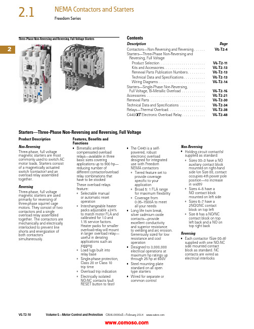
2Three-Phase Non-Reversing and Reversing, Full Voltage StartersContentsDescription PageContactors—Non-Reversing and Reversing. . . . . .V5-T2-4Starters—Three-Phase Non-Reversing andReversing, Full VoltageProduct Selection . . . . . . . . . . . . . . . . . . . . . . .V5-T2-11Kits and Accessories. . . . . . . . . . . . . . . . . . . . .V5-T2-13Renewal Parts Publication Numbers. . . . . . . . .V5-T2-13Technical Data and Specifications. . . . . . . . . . .V5-T2-13Wiring Diagrams. . . . . . . . . . . . . . . . . . . . . . . .V5-T2-14Starters—Single-Phase Non-Reversing,Full Voltage, Bi-Metallic Overload . . . . . . . . . . . .V5-T2-15Accessories . . . . . . . . . . . . . . . . . . . . . . . . . . . . . .V5-T2-21Renewal Parts . . . . . . . . . . . . . . . . . . . . . . . . . . . .V5-T2-30Technical Data and Specifications . . . . . . . . . . . . .V5-T2-34Relays—Thermal Overload. . . . . . . . . . . . . . . . . . .V5-T2-38C440/XT Electronic Overload Relay. . . . . . . . . . . .V5-T2-48Starters—Three-Phase Non-Reversing and Reversing, Full VoltageProduct DescriptionNon-ReversingThree-phase, full voltagemagnetic starters are mostcommonly used to switch ACmotor loads. Starters consistof a magnetically actuatedswitch (contactor) and anoverload relay assembledtogether.ReversingThree-phase, full voltagemagnetic starters are usedprimarily for reversing ofthree-phase squirrel cagemotors. They consist of twocontactors and a singleoverload relay assembledtogether. The contactors aremechanically and electricallyinterlocked to prevent lineshorts and energization ofboth contactorssimultaneously.Features, Benefits andFunctions●Bimetallic ambientcompensated overloadrelays—available in threebasic sizes coveringapplications up to 900 hp—reducing number ofdifferent contactor/overloadrelay combinations thathave to be stockedThese overload relaysfeature:●Selectable manualor automatic resetoperation●Interchangeable heaterpacks adjustable ±24%to match motor FLA andcalibrated for 1.0 and1.15 service factors.Heater packs for smalleroverload relay will mountin larger overload relay—useful in deratingapplications such asjogging●Load lugs built intorelay base●Single-phase protection,Class 20 or Class 10trip time●Overload trip indication●Electrically isolatedNO-NC contacts (pullRESET button to test)●The C440 is a self-powered, robustelectronic overloaddesigned for integrateduse with FreedomNEMA contactors●Tiered feature set toprovide coveragespecific to yourapplication●Broad 5: 1 FLA rangefor maximum flexibility●Coverage from0.05–1500A to meetall your needs●Long life twin break,silver cadmium oxidecontacts—provideexcellent conductivityand superior resistanceto welding and arc erosion.Generously sized for lowresistance and cooloperation●Designed to 3,000,000electrical operations atmaximum hp ratings upthrough 25 hp at 600V●Steel mounting platestandard on all opentype starters●Wired for separate orcommon controlNon-Reversing●Holding circuit contact(s)supplied as standard:●Sizes 00–3 have a NOauxiliary contact blockmounted on right-handside (on Size 00, contactoccupies 4th power poleposition—no increasein width)●Sizes 4–5 have aNO contact blockmounted on left side●Sizes 6–7 have a2NO/2NC contactblock on top left●Size 8 has a NO/NCcontact block on topleft back and a NO ontop right backReversing●Each contactor (Size 00–8)supplied with one NO-NCside mounted contactblock as standard. NCcontacts are wired aselectrical interlocks2Freedom SeriesProduct SelectionWhen Ordering Supply ●Catalog number ●Heater pack number (see selection table, Pages V5-T2-40 to V5-T2-42) or full load currentT ype AN16/AN56 NEMA—Manual or Automatic Reset Overload Relay—Non-Reversing and Reversing 1Magnet Coils—AC or DC Starter coils listed in this section also have a 50 Hz rating as shown in the adjacent table. Selectrequired starter by catalog number and replace themagnet coil alpha designation in the catalog number (_) with the proper code suffix from the table.For Sizes 00–2 and 5–8, the magnet coil alpha designation will be the next to last digit of the listed catalog number.EXAMPLE: For a 380V, 50 Hz coil, change AN16BN0_C to AN16BN0L C. For all other sizes, the magnet coil alpha designation will be the last digit of the listed catalog number.For DC Magnet Coils , see Accessories, Pages V5-T2-28 and V5-T2-29.AC SuffixNotes1Starter catalog numbers do not include heater packs. Select one carton of three heater packs. Heater pack selection, Pages V5-T2-40 to V5-T2-42.2Maximum horsepower rating of starters for 380V 50 Hz applications:3Underscore (_) indicates coil suffix required, see AC Suffix table.4The service-limit current ratings represent the maximum rms current, in amperes, which the controller shall be permitted to carry for protracted periods in normal service. At service-limit current ratings, temperature rises shall be permitted to exceed those obtained by testing the controller at its continuous current rating. The current rating of overload relays or trip current of other motor protective devices used shall not exceed the service-limit current rating of the controller.5Common control. For separate 120V control, insert letter D in 7th position of listed catalog number. Example: AN56VN D 0CB.6NEMA Sizes 00 and 0 only.7NEMA Sizes 00 and 0 only. Sizes 1–8 are 24/60 only.NEMA Size Continuous Ampere Rating Service-Limit Current Rating (Amperes) 4Maximum UL Horsepower 2Three-PoleNon-Reversing 3Three-Pole Reversing 3Vertical Reversing 3Single-Phase Three-Phase 115V 230V 208V 240V 480V 600V Catalog Number Catalog Number Catalog Number 009111/311-1/21-1/222AN16AN0_C AN56AN0_C —01821123355AN16BN0_CAN56BN0_C AN56BNV0_12732237-1/27-1/21010AN16DN0_B AN56DN0_B AN56DNV0_2455237-1/210152525AN16GN0_B AN56GN0_B AN56GNV0_390104——25305050AN16KN0_AN56KN0_AN56KNV0_4135156——4050100100AN16NN0_AN56NN0_AN56NNV0_5270311——75100200200AN16SN0_B AN56SN0_B —6540621——150200400400AN16TN0_C AN56TN0_C —7810932——200300600600AN16UN0_B AN56UN0_B —8 512151400——400450900900AN16VN0_BAN56VN0_B—Size 0Non-Reversing StarterSize 1Reversing StarterCoil Volts and Hertz Code Suffix Coil Volts and Hertz Code Suffix 120/60 or 110/50A 380–415/50L 240/60 or 220/50B 550/50N 480/60 or 440/50C 24/60, 24/50 7T 600/60 or 550/50D 24/50U 208/60E 32/50V 277/60H 48/60W 208–240/60 6J 48/50Y 240/50K48/50YNEMA Size 00012345678Horsepower1-1/25102550751503006009002Two-Speed Selective ControlWhen Ordering Supply●Catalog number plusmagnet coil code suffix.Example: Size 0—AN700BN022B●Heater pack number or fullload current for each speedFor two-speed other thanselective control:●Catalog number plusmagnet coil code suffix andoption required. Example:AN700BN022B exceptcompelling●Heater pack number or fullload current for each speedNote: Two-speed startersare designed for starting andcontrolling both separate(two-winding) and reconnectable(one-winding) motors. Separatewinding, WYE-WYE motorshave a separate winding foreach speed. Reconnectable,consequent pole motors use thesame winding for both speeds. Allstandard starters are wiredfor selective control.Separate Winding 1Reconnectable Winding 1Magnetic Coils—AC or DCNotes1 If branch circuit protective device is 45A or greater, C320FBR1 fuse kit(s) may be required for circuit protection per NEC 530-072.2 NEMA Sizes 00 and 0 only. Sizes 1–5 are 24/60 only.Maximum Horsepower—60/50 HertzNEMASizeOpen TypeCatalog Number Constant or Variable Torque Constant Horsepower115V200V230V460V/575V115V200V230V460/575V1-1/233512230AN700BN022_37-1/27-1/2102557-1/21AN700DN022_—101525—7-1/210202AN700GN022_—253050—2025403AN700KN022_—4050100—3040754AN700NN022_—75100200—60751505AN700SN022_Prices of starters do not include heater packs. Select two packs (two overload relays, one for each speed). Heater pack selection, Pages V5-T2-40 to V5-T2-42.Maximum Horsepower—60/50 HertzNEMASizeOpen TypeConstant or Variable Torque Constant HorsepowerConstant orVariable TorqueConstantHorsepower 115V200V230V460V/575V115V200V230V460/575V Catalog Number Catalog Number1-1/233512230AN700BN0218_AN700BN0219_37-1/27-1/2102557-1/21AN700DN0218_AN700DN0219_—101525—7-1/210202AN700GN0218_AN700GN0219_—253050—2025403AN700KN0218_AN700KN0219_—4050100—3040754AN700NN0218_AN700NN0219_Prices of starters do not include heater packs. Select two packs (two overload relays, one for each speed). Heater pack selection, Pages V5-T2-40 to V5-T2-42.Coil Voltage and Hz Code Suffix Coil Voltage and Hz Code Suffix Coil Voltage and Hz Code Suffix120/60 or 110/50A277/60H24/60, 24/50 2T240/60 or 220/50B208–240/60J24/50U480/60 or 440/50C240/50K32/50V600/60 or 550/50D380–415/50L48/60W208/60E550/50N48/50YTwo-WindingAN700DN022One-WindingAN700BN0218One-WindingAN700DN02182Freedom SeriesKits and Accessories●Auxiliary contacts, contactor mounted—Pages V5-T2-25 to V5-T2-27●Transient suppressor, for magnet coil—Page V5-T2-24●Timers—solid-state and pneumatic, mount on contactor—Page V5-T2-22Renewal PartsPublication Numbers●See Page V5-T2-30Technical Data and SpecificationsWire (75°C) Sizes—AWG or kcmil—NEMA Sizes 00–2—Open and EnclosedWire (75°C) Sizes—AWG or kcmil—NEMA Sizes 3–8—Open and EnclosedPlugging and Jogging Service Horsepower Ratings 3Notes1Minimum per NEC. Maximum wire size: Sizes 00 and 0 to 8 AWG and Sizes 1–2 to 2 AWG.2Two compartment box lug.3Maximum horsepower where operation is interrupted more than 5 times per minute, or more than 10 times in a 10 minute period. NEMA Standard ICS2-1993 table 2-4-3.NEMA SizeWire Size 1 Cu OnlyPower T erminals—Line 0012–16 AWG stranded, 12–14 AWG solid 08–16 AWG stranded, 10–14 AWG solid 18–14 AWG stranded or solid23–14 AWG (upper) and/or 6–14 AWG (lower) stranded or solid 2Power T erminals—Load—Cu Only (stranded or solid)00–014–6 AWG stranded or solid 1–214–2 AWG stranded or solidControl T erminals—Cu Only 12–16 AWG stranded, 12–14 AWG solidNEMA SizeWire Size 2Power T erminals—Line and Load 31/0–14 AWG Cu/Al4Open—3/0–8 AWG Cu; Enclosed—250 kcmil—6 AWG Cu/Al 5750 kcmil—2 AWG; or (2) 250 kcmil—3/0 AWG Cu/Al 6(2) 750 kcmil—3/0 AWG Cu/Al 7(3) 750 kcmil—3/0 AWG Cu/Al 8(4) 750 kcmil—1/0 AWG Cu/AlControl T erminals—Cu Only 12–16 AWG stranded, 12–14 AWG solidNEMA Size 200V 230V 460V 575V 00—1/21/21/201-1/21-1/2221335527-1/21015153152030304253060605607515015061251503003002Wiring DiagramsThree-Phase and Single-Phase Applications。
电子保护设备用户手册说明书

allowable
Any
Fixing
Screw / DIN rail 35mm
Weight
g 320
UL technical data
Motor Disconnect
at 480V kA 50
at 600V kA 50
protection
Fuse or CB
Group Motor Installation
2/3
SM1R0040
MOTOR PROTECTION CIRCUIT BREAKER TYPE E, IEC BREAKING CAPACITY ICU 100KA AT 400V, 0.25...0.4A
ETIM classification ETIM 8.0
EAC
EC000074 Motor protection circuit-breaker
3/3
SM1R0040
The characteristics described in this document are subject to updates or modifications at any time. The descriptions, technical and functional information, illustrations and instructions in this brochure are purely illustrative, and are consequently not contractually binding
SM1R0040
MOTOR PROTECTION CIRCUIT BREAKER TYPE E, IEC BREAKING CAPACITY ICU 100KA AT 400V, 0.25...0.4A
电动机保护断路器手册说明书
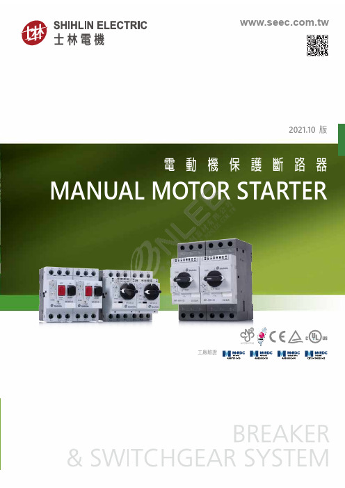
電動機保護斷路器MANUAL MOTOR STARTER2021.10 版工廠驗證結構緊湊符合標準安全性M3~MR-32S MR-32R 接觸器電動機orMR-65R2MMS允許操作環境溫度:-25 ~ 55℃允許儲存環境溫度:-50 ~ 80℃海拔高度:安裝地點海拔高度不能超過2000m污染等級:抗污染等級為3,可在IEC60947標準中定義三級污染環境中運行安裝條件:(1). 安裝面與垂直面傾斜角不能超過30°(2). 採用標準導軌安裝(3). 應安裝和使用在無明顯晃動、沖擊及震盪的地方◆◆◆◆◆額定工作電流:0.16~32A(32AF),13~65(65AF)系列號:S -按鈕式(32AF)、R-旋轉式(32/65AF)框架等級:32,65電動機保護斷路器正常工作條件及安裝條件額定工作電流過載脫扣設定範圍磁脫扣電流產品型號In (A)In (A)Id ±20% (A)按鈕式0.160.1-0.161.92MR-32S-0.160.250.16-0.253MR-32S-0.250.40.25-0.44.8MR-32S-0.40.630.4-0.637.56MR-32S-0.6310.63-112MR-32S-11.61-1.619.2MR-32S-1.62.5 1.6-2.530MR-32S-2.54 2.5-448MR-32S-46.34-6.375.6MR-32S-6.3106-10120MR-32S-10149-14168MR-32S-14LTI >2.5~4A100/100100/100100/10080/804~6.3A100/100100/10050/5050/506~10A100/100100/10015/1510/109~14A100/10015/7.58/46/4.513~18A100/10015/7.58/46/4.517~23A50/5015/66/34/320~25A50/5015/66/34/324~32A50/5010/56/34/3自動●IP20100,000100,000允許操作環境溫度-25 ~ 55℃允許儲存環境溫度-50 ~ 80℃MR-65R3PUi (V)690額定耐受衝擊電壓 Uimp (kV)650/60 Hz4MMSMR-AUMR-AM-11MR-AD-0110MR-AD-0101MR-AD-1010MR-AD-10011NO+1NC D2D1URearm RESET060508>>C2C1附件齊全側裝輔助接點組(MR-AN)短路信號接點組(MR-AM)上裝輔助接點組(MR-AE)電壓跳脫裝置(MR-AS)欠電壓跳脫裝置(MR-AU)or MR-32S MR-32R 故障信號接點組(MR-AD)MR-65Roror or or電 動 機 保 護 斷 路器5MMS 應用例圖【範例一】【範例二】ororororAPS-11N S-P ○○N *MEU-11N MPU-11N S-P ○○NML-01NAP-4NAP-2NorAPS-11N S-P ○○NL MEU-11N MPU-11N S-P ○○NLMR-65R-○○WKM-65NLML-01NAP-4NAP-2NWKX-65NL註1.註6MMS特性曲線圖MMS 接線模組名稱MMS+MC 接線模組正逆轉接線模組圖示接線模組型號WKM-18N WKM-38N WKMD-18N WKMD-38N WKM-65NL WKX-18N WKX-38N WKX-65NL MMS 適用型號MR-32S MR-32R MR-65RMR-32S MR-32RMR-65R接觸器適用型號S-P9N S-P9N3S-P9N4S-P12N S-P12N3S-P12N4S-P18N S-P18N3S-P18N4S-P25N S-P25N3S-P32N S-P32N3S-P38N S-P38N3SD-P9N SD-P12N SD-P18N SD-P25N SD-P32N SD-P38N S-P40NL S-P50NL S-P65NLS-P9N S-P9N4S-P12N S-P12N4S-P18N S-P18N4SD-P9N SD-P12N SD-P18NS-P25N S-P32N S-P38N SD-P25N SD-P32N SD-P38NS-P40NL S-P50NL S-P65NL36007200300120060060120301050.5120.20.10.050.010.02144001.201.05504030201234567811.216.8Tripping characteristicMR-65R(倍)X rated current t (s )Multiple of setting value × In (A)Tripping characteristicMR-32S/R1.201.0550403020123456789.614.4(倍)X rated current 36007200300120060060120301050.5120.20.10.050.010.0214400t (s )Multiple of setting value × In (A)65.512.9TEST 1L12L13L25L34L26L3144544.614.3267514MR-32R-Y13.613.6168MMS◆ 側裝輔助接點組重量:0.10kg37.6458749.66618短路信號接點組4587◆ 側裝輔助接點組◆ 電壓/欠電壓跳脫裝置重量:0.10kg 37.6458749.66618◆ 側裝輔助接點組◆ 電壓/欠電壓跳脫裝置重量:0.10kg 37.6458749.66618◆ 短路信號接點組4587短路信號接點組◆ 側裝輔助接點組重量:0.10kg 37.6458749.66618◆ 短路信號接點組4587◆ 故障信號接點組2110.1,000.mms01-8www本公司保留變更修改機種、規格之權利,恕不另行通知。