电机保护器说明书(MAM-B)
螺杆空压机MAM-200

螺杆空压机微电脑控制器MAM-KY02S(B)-(Ⅷ)型(中文液晶显示-200)用户手册继电器输出控制之交流接触器等感性负载必须接突波吸收器。
上电之前仔细检查输入/输出配线。
本机体之接地端子正确接地(第三种接地),可提高产品的抗杂讯能力。
电机额定电流(跳机电流)的设定按电机铭牌额定电流╳电机过载倍数/1.2倍特点:● LCD 中英文显示● 对电机具有短路、堵转、缺相、过载、不平衡等全方位保护功能 ● 对电机具有起停控制、运行控制 ● 对空压机进行防逆转保护● 对多点温度进行检测与控制保护 ● 自动调节负荷率控制压力平衡 ● 高度集成,高可靠性,高性价比 ● 远程/机旁选择控制● 联动/独立选择运行 ● RS-485通讯功能一、基本操作1、按键说明图1I——起动键:按此键可起动电机运行O——停机键:按此键可停止电机运行S——设定键:修改完数据后,按此键确认数据存储输入❽——上移键:数据修改时,按此键上翻修改该数位;在菜单选择时作为选择键。
❾——下移键:数据修改时,按此键下翻修改该数位;在菜单选择时作为选择键。
❼——移位键/确认键:修改数据时,此键作为移位键;在菜单选择时作为确定键。
❾❽——手动加载/卸载键:在手动方式下,在一定压力范围内按此键可加载或卸载。
↳——返回键/复位键:在菜单操作时作为返回键返回上一级菜单;故障停机时,按此键复位。
2、状态显示与操作机组通电后显示如下界面:5秒后显示以下主界面:按“❾”进入以下菜单选择界面:a、运行参数查看按“❾”或“❽”移动黑色滚动条到“运行参数”菜单后,按确认键“❼”后弹出下一级菜单:再按“❼”弹出如为最后一级菜单,界面不会出现黑色滚动条,按返回键“↳”返回上级菜单或主界面。
如在某一界面停止操作,数秒钟后自动返回主界面。
用“❾”、“❽”移动键、确认键“❼”和返回键“ ↳ ”用同样方法可完全观察到运行时间、本次运行时间、维护参数、历史故障、出厂日期、现场故障等运行参数并返回到上级菜单。
智能马达保护器使用手册新

智能马达保护器使用手册一、概述1.1用途ZNB-200型智能低压电动机保护装置(以下简称装置)是我公司研制的低压智能配电产品,该产品针对交流380V的低压电动机设计,集保护、测量、信号等功能于一体,集中实现了低压电动机的综合保护、测量及操作与控制。
1.2使用环境a)环境温度:-10℃~+55℃,b)贮存温度:-25℃~+70℃,在极限值下不施加激励量,装置不出现不可逆变化,温度恢复后,装置应能正常工作;c)相对湿度:不超过85%;d)大气压力:86kPa~106kPa;e)使用地点不允许有爆炸危险的介质,周围介质中不应含有腐蚀金属和破坏绝缘的气体及导电介质,不允许充满水蒸气及有严重的霉菌存在;f)使用地点应具有防御雨、雪、风、沙、灰的设施。
1.3技术特点本装置具有如下主要技术特点:a)集保护、测量、信号等功能于一体;b)具有接地保护、过流保护、过压保护、低压保护、堵转保护、适合增安电机的TE 保护、缺相保护、逆序保护、过热保护、不平衡保护、启动时间过长保护、轻载保护共12种保护。
各种保护功能均可选择投/退(启动时间过长保护始终投入)。
除启动时间过长保护、堵转保护、缺相保护和逆序保护只能动作于跳闸外,其余都可编程为动作于报警或跳闸。
c)能够测量的电气参数有:电压(Uab,Ucb)、三相电流、有功功率、无功功率、视在功率、功率因数、正序电流、负序电流、零序电流;d)有一个事件报警出口;e)小型化外形尺寸,适合于各种开关柜型;f)采用先进的32位ARM芯片,运算速度快,抗干扰能力强。
g)保护原理成熟可靠,能够经历长时间的现场运行考验;h)大屏幕LCD汉字显示,全中文菜单操作;二、主要技术参数2.1工作电源a)额定电源电压:220V,允许偏差:直流 -20 %~+10 %。
交流 -15 %~+10 %b)直流电源纹波系数:不大于5%。
c)额定频率:50Hz ,允许偏差:-5%~+5%;2.2交流回路a)交流电流:1~75KW电机使用我公司的CT1-CT7(根据电动机功率选配),大于75KW则需外配互感器和我公司提供的互感器配合使用。
电动机保护说明书

二、 产品安装 .........................................................................................................................................................6
2.1 安装前注意事项............................................................................................................................................6 2.2 保护器开孔安装............................................................................................................................................6 2.3 外置互感器螺丝固定....................................................................................................................................6 2.4 外置电流互感器典型规格 ............................................................................................................................7 2.5 漏电流互感器................................................................................................................................................7
电动机保护器说明书

电动机保护器说明书电动机保护器说明书1.概述微机监控电机保护器适用于AC380V、AC660V低压系统,作为低压异步电动机和增安型电动机的保护、监测和控制的新一代智能化综合装置。
除了先进的电动机保护、监控功能,还提供了设备运行和跳闸的记录以及额定参数等重要信息,并且采用现场总线方式结构,为现代化的设备管理带来很大的便利;广泛用于石油、化工、电力、冶金、煤炭、轻工、纺织等行业。
符合标准:GB3836.3-2000、GB14048.4-2003、IEC2552.特点●“tE时间保护”符合有关增安型防爆电动机过载保护的国家标准(GB3836.3-2000)●交流采样,测量A、B、C三相电流及控制回路电压●现场显示电动机运行状态,保存三次电动机故障跳闸记录●一路保护输出,一路自定义继电器输出,一路4~20mA电流输出或RS485接口●高清晰度宽温液晶显示,并具有背景光,跟随电动机运行状态和用户要求实时显示●三相电流不平衡、断相、过压、欠压、自启动等功能用户可取可舍●采用E2PROM存储技术,实现参数电设定,掉电后设定参数仍保存下来,勿须再设定●采用RS485通信总线,可广泛用于各种监控系统作为带有电机保护及控制的智能化监控单元●一机多用,可取代电流表、电压表、热继电器、电流互感器、时间继电器和漏电继电器等3.主要功能保护功能:过流、堵转、断相、三相电流不平衡、过压、欠压、短路、漏电(选配)等故障保护测量功能:三相电流、控制回路电压的测量和显示通用功能:增安型电动机保护、三相异步电动机保护、馈线保护,三种保护装置通用通信功能:通过本保护器的RS485接口与上层系统通信。
总线接口支持参数设置、控制及监测等功能,支持Modbus通信协议。
一般采用RS485总线接口进行物理连接,通常上位机或PLC设备作为主站,本保护器作为子站。
电流输出:4~20mA电流输出,20mA对应的电流值可设。
4.型号说明微机电动机保护监控装置适用于AC660V及以下低压系统,作为低压电动机馈线终端的保护、监测和控制的新一代智能化综合装置。
电机智能保护器配置手册说明书
How to configure, monitor, and control Motor Insight via Modbus, DeviceNet, and PROFIBUSApplicationMotor Insight T is an advanced motor protective relay with thermal motor overload, supply,and load protection; configurable ground fault detection; power monitoring; an intuitive user interface; and optional communications. The optional communications allow for remote control and reset of faults, and remote monitoring of numerous operating and configuration parameters. The communication modules also include inputs that can be usedto bring the status of sensors or switches backto the system controller, as well as outputs to control the contactor or turn on pilot lights.OverviewThe industrial networks supported by the Motor Insight relay are all open networks. This means that there are many software tools already available that can be used to configure the device over these networks. Each of the supported networks will be discussed in this document, including suggestions for various configuration tools, many of which are free downloads from the Internet. In many cases, the network tools supplied by the manufacturerof the network master can be used to configure any device on that network.Overview of Modbus T, DeviceNet E and PROFIBUS TFor most applications, the Motor Insight relay parameters can be easily configured using its intuitive user interface. Then, the communication network master can be used to control and monitor the device during operation. This network master reads status information from each slave device and writes control information. The communication interface modules forMotor Insight allow control for the following:1. Remote reset of a fault2. Remote trip3. Control of on-board field outputs Numerous parameters are available to be monitored from Motor Insight, including:1. Device status bits2. rms current IA3. rms current IB4. rms current IC5. rms current average6. rms voltage VAB7. rms voltage VBC8. rms voltage VCA9. rms voltage average10. Total kW11. Voltage unbalance percent12. Current percent13. Apparent power factor14. Residual ground current deciamps15. Frequency16. Overload thermal pile17. Trip reason18. Overload status19. Error code20. Field inputsThe following is a discussion concerning the third-party software tools available for the open networks supported by Motor Insight. ModbusMotor Insight supports both Modbus RTU and Modbus ASCII modes, as well as baud rates from 9600 to 115.2K baud. It will communicate with any Modbus master.The unique aspect of Modbus is that special configuration tools are typically not necessaryas they are with many other industrial networks. The reason is that Modbus requires Modbus Data Register addresses for all parameters in all Modbus devices. This allows a Modbus master to easily read and write data to a Modbus slave device for configuration, control, and monitoring purposes. Motor Insight is no different. It has assigned a Modbus Data Address to all available parameters. This information is publishedin the Motor Insight overload and monitoring relays user manual, publication MN04209001E.Eaton Corporation Electrical Sector1111 Superior Ave. Cleveland, OH 44114United States877-ETN-CARE (877-386-2273) © 2010 Eaton CorporationAll Rights ReservedPrinted in USAPublication No. AP04209004E / Z9775 August 2010PowerChain Management is a registered trademark of Eaton Corporation.All other trademarks are property of their respective owners.Application Paper AP04209004E Effective August 2010How to configure, monitor, and control Motor Insight via Modbus, DeviceNet,and PROFIBUSIf a third-party Modbus software package is desired to configureor verify the configuration or operation of Motor Insight, there are numerous software tools available. Many of these tools are free downloads, such as ModScan. Others can be found by simply searching the Web for Modbus Software Tools.Eaton has a line of electronic operator interface devices called HM i.A program for a 4-inch HM i is available as a free download from /motorinsight or via this direct link. This program communicates via Modbus to multiple Motor Insight devices. It contains screens for configuring, monitoring, and controlling upto 16 Motor Insights from a single HM i. To obtain the HM i software needed to download the program to an HM i, visit / electrical. Then, click the “Tools & Downloads” link. Next, select “Software Downloads.” On the next page, under the Products drop-down, select “Operator Interface...” and then select “HM i Operator Interface Configuration Software.” Also note that the HM i software allows for changing the HM i program so it can be downloaded to any size HM i: 4-, 6-, 8-, or 10-inch unit.Another source of available Modbus tools can be found on the official Modbus Web site: .DeviceNetUnlike Modbus, where all parameters in a device have a data address assigned to them, DeviceNet slave devices use input and output assemblies. Each input assembly will include the same status bits indicating operational status of the device. The various input assemblies differ by the additional data that can be monitored with each. The Motor Insight relay has five different input assemblies. Two of these input assemblies allow the user to select the parameters to monitor. The various output assemblies are for control. They provide the ability to reset faults, trip the overload, and turn the outputs on-board the DeviceNet module on and off. DeviceNet is an open network that requires a software tool to configure slave devices and to map their data into the scan list of the master. The manufacturer of the DeviceNet master will provide a software tool to map slave devices into the scan list of the master so the system controller can control and monitor each Motor Insight. Motor Insight contains an intuitive user interface for configuration, but when on a DeviceNet network, it can be configured by any third-party DeviceNet commissioning tool as well. The DeviceNet specification requires that all DeviceNet products have an eds file (electronic data sheet). This file is a text file that is used to uniquely define each parameter in the device. DeviceNet commissioning tools are designed with the ability to import eds files for any valid DeviceNet slave device. The software tool can then be used to configure the device. There are two eds files and an icon file available for Motor Insight. They may be downloaded from/motorinsight. These files can then be imported into any valid DeviceNet commissioning software, such as:1. Eaton’s CHStudio E2. Eaton’s ELCSoft (DNET CONFIG Tool)3. Rockwell’s RSNetWorx E for DeviceNetCHStudio is a free download from the Eaton Web site; searchfor CHStudio and download the software and activation code.It can be used to configure any DeviceNet slave device, but notthe network master.ELCSoft is the programming software for the Eaton PLC line called ELC. This PLC line includes a complete DeviceNet master, the ELC-CODNETM module. The commissioning software is included in the ELCSoft programming software. It can configure any DeviceNet slave device by importing the eds file for the device and can fully configure the ELC-CODNETM DeviceNet master module.The manufacturer of the network master typically supplies the software tools needed to configure the master. RSNetWorxfor DeviceNet can be purchased from Rockwell or a Rockwell distributor. Motor Insight eds files can be imported into RSNetWorx for DeviceNet, allowing the software to configurethe Motor Insight and a Rockwell DeviceNet master.Once all slave devices on a DeviceNet network have been configured and mapped into the DeviceNet master’s scan list, the master will continuously poll the slave devices, like the Motor Insight, writing control data to them and monitoring various parameters. Motor Insight has more data available to monitor than any other overload relay of its type. This information is published in the Motor Insight overload and monitoring relay user manual, MN04209001E.Another source of available DeviceNet tools can be found on the official DeviceNet Web site: .PROFIBUSPROFIBUS is very similar to DeviceNet in that the network configuration tools are typically supplied by the manufacturer of the PROFIBUS master. There is also a file for PROFIBUS similar to the eds file for DeviceNet, called a GSD file. All valid PROFIBUS slave devices must have a GSD file. This file is imported into the PROFIBUS commissioning tool or the programming software, allowing the software to configure the device and map its I/O data so the PROFIBUS master can poll the slave devices for control and monitoring purposes. These PROFIBUS tools are supplied bythe manufacturer of the PROFIBUS master. The GSD file may be downloaded from /motorinsight. This file can then be imported into any valid PROFIBUS software tool, such as Siemen’s SIMATIC Software. Other PROFIBUS network product vendors are Woodhead Connectivity, Bihl+Wiedemann GmbH and PROCENTEC. Another source of available PROFIBUS tools can be found on the official PROFIBUS Trade Organization Web site: /.Supporting documentationMotor Insight User Manual MN04209001E Motor Insight DeviceNet Instructional Leaflet IL04209005EMotor Insight Modbus Instructional Leaflet IL04209004EMotor Insight PROFIBUS Instructional Leaflet IL0420900XEELC System Manual MN05003003EELC-CODNETM Instructional Leaflet IL05001003EHM i User manual MN04802014EAdditional helpIn the event that additional help is needed, please contact the Technical Resource Center at 1-877-ETN-CARE (386-2273).。
ABB电机保护设备说明书

TA25DU32TA25DU11TA25DU14TA25DU3.1TA25DU4.0 TA25DU2.4Thermal Overload RelaysTripping Class 20N e wABBMotor Protection — generalIt is very important to choose an adequate protective device for the safety of the motor during operation and for its durability.The efficiency of protection methods varies according to the ap-plication. The overview below will help you to choose.There is no general rule and we are available to advise you for special applications and especially in the case of difficult start-ing. An economic and effective protection are thermal overload relays with protection against: > Overload> Phase failure imbalance > Phase loss Description• Available for starter construction with A Line contactors and separate panel mounting• Designed for close couple mounting – separate base mounting available for all overload relays• Full automatic function, Manual reset, Test phase or Reset can also be adjusted to function as a stop button • Remote trip and reset option available• Screwdriver guide holes, all terminal screws are available from the front • Trip indication• Ambient compensation -25 °C to +55 °C (-13 °F to +131 °F)Tripping classes of the thermal overload relays Standard tripping classes are 10 A, 10, 20, 30. The tripping class indicates according to IEC 60947-4-1 the maximum tripping time in seconds under specified conditions of test at 7.2 times the setting current and specifics tripping and non trip-ping times for 1.5 and 7.2 times the setting current.Construction and function • GeneralThermal O/L relays and their accessories meet UL, Nema, CSA and most other important international standards (IEC), European standards (EN) and the most important national standards. They meet the certification and approval directives required through-out the world.Thermal overload relays are 3 pole. The motor current flows through their bimetals (1 per phase) which are indirectly heated. Under the effect of the heating, the bimetals bend, cause the relay to trip and the position of the auxiliary contacts to change.The relay setting range is graduated in amps. In compliance with international and national standards, the setting current is the motor nominal current and not the tripping current (no tripping at 1.05 x setting current, tripping at 1.2 x setting current). The tripping curves (cold or warm starting, 3 phases and 2 phases) are shown in the main catalog.The relays are built to be self protecting in the event of an over-load until the short circuit protection device is activated.Function of the thermal overload relaysTerminals L1, L3, L5Manual test Manual orautomatic resetTrip indication light Tripping contact (95,96)Terminals T1, T2, T3Frame size TA ... DU Amp setting rangeSignalingcontact (97, 98)Reset buttonTimeIe (adjusted current)No Tripping at 1.05 IeTripping at 1.2 Ie within 2 hoursClass 10 4 - 10 sec1.2 Ie7.2 IeClass 20 6 - 20 secClass 30 9 - 30 secThermal Overload Relays with Trip Class 20Ordering data for the "New additional Assortment"TA25DUTA42DUTA75DUTA80DUType …1“ co-ordination according to IEC 60947-4-1: Under short-circuit conditions, the starter shall cause no danger to persons or installation and may not be suitable for further service without repair and replacement of parts.Type …2“ co-ordination according to IEC 60947-4-1: Under short-circuit conditions, the contactor or starter shall cause no danger to persons or installation and shall be suitable for further use. The risk of contact welding is recognized, in which case the manu-facturer shall indicate the measures to be taken as regards the maintenance of the equipment Standard technical data, operating data and dimensions see TA...Relay Main CatalogThermal Overload Relays with Trip Class 20Resistances and power losses per phaseShort-circuit protectionThermal Overload Relays with Trip Class 20Technical dataShort-circuit ratingsB r o c h u r e N o . 2CD C 106 015 B 0201 P r i n t e d i n t h e F e d e r a l R e p u b l i c o f G e r m a n y (12/05 • 1 • G V D )ABBABB Global Contact DirectoryThe ABB Contact Directory (/contacts/) helps you find local contacts for ABB products in your country. Please select the relevant product group from the dropdown menu to the right or from the page.ABB STOTZ-KONTAKT GmbH P . O. Box 10 16 80D-69006 HeidelbergTelephone: ++49 62 21 / 701-0Telefax: ++49 62 21 / 701-729http://www.abb.de/stotz-kontaktTripping times of thermal overload relays as a function of a multiple of the setting current from cold state (tolerance +/- 20% of the tripping time).Thermal Overload Relays with Trip Class 20Table for tripping timeTA25DU32TA25DU11TA25DU14TA25DU3.1TA25DU4.0 TA25DU2.4。
电机保护设备说明书.pdf_1719234974.3339334
Degree of Protection Pollution Degree Connecting Capacity Auxiliary Circuit
Connecting Capacity
2
1SAZ700404F0001
45 mm 76.7 mm 53.5 mm
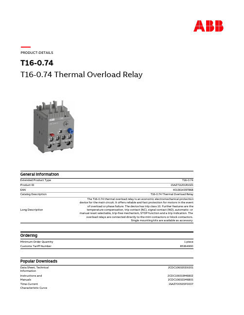
PThermal Overload Relay
General Information
Extended Product Type Product ID EAN Catalog Description
Long Description
Ordering
Certificates and Declarations (Document Number)
ABS Certificate
1SAA941001-0102
T16-0.74
BV Certificate CB Certificate CQC Certificate cUL Certificate Declaration of Conformity - CCC Declaration of Conformity - CE DNV GL Certificate EAC Certificate Environmental Information GL Certificate GOST Certificate Instructions and Manuals LR Certificate RINA Certificate RMRS Certificate RoHS Information Time-Current Characteristic Curve UL Certificate
电机保护器说明书(MAM-B)
11、电源功耗:小于1.5VA;
12、降压起动转换时间:0~999秒;降压起动转换电流:0~999安。
六、结构尺寸与接线端子
图2、接线端子排列
端子:1、2为保护输出,3、4为报
警输出,5、6为电源,7、8为
控制输出(可选为常开或常闭)。
注:接线时请按保护器的功能及相应的接线
工作原理:
a、起动:①HK处于自动状态时,按QA起动键,C3得电,C2得电,电机处于降压运行,当保护器检测到主回路有电流流过时开始计时,同时把检测电流与设定的转换电流比较,当计时时间到或起动电流小于设定的转换电流时,常开触点(7、8)闭合两秒,ZJ一直得电,C3失电,C1得电旁路自耦变压器。电机全压运行。
2、对于有Y—△转换电路,保护器应安装在能测电机线电流的地方,以便按电机铭牌设定。
3、正确设定保护器的设定电流,由于保护器已按设定电流的1.2倍作为过载计算,所以应按电机的
铭牌额定设定。特别注意具有△/Y两种接法的电机,铭牌有两种接法的额定电流,选型和安装
时都要注意这一情况。
4、保护器应工作在正常电流范围内。
以上为只带起动控制功能保护器的基本操作,带欠载等其它功能时操作略有不同。
注:在设定状态,10秒内如无任何操作,保护器返回停机状态,数据不被保存。如修
改完某项数据,只要按住“M”键2秒就可保存修改值。
2、运行状态数据查看
电机起动运行后,监控器将循环显示A、B、C三相电流值和电机额定电流值。如需暂停循环显示可按“”键,如需恢复循环显示可再一次按“”键。但在运行状态下的保护参数是不可修改的。
b、停机:按停机按钮TA,切断所有接触器线圈电源,电机停止运转。
c、故障停机:当保护器检测到电机故障将要发生时,保护器保护输出触点(1、2)断开,切断所有接触器电源,电机停转。同时报警触点(3、4)闭合发出报警信号。只有故障排除,保护器复位后方可起动电机。
- 1、下载文档前请自行甄别文档内容的完整性,平台不提供额外的编辑、内容补充、找答案等附加服务。
- 2、"仅部分预览"的文档,不可在线预览部分如存在完整性等问题,可反馈申请退款(可完整预览的文档不适用该条件!)。
- 3、如文档侵犯您的权益,请联系客服反馈,我们会尽快为您处理(人工客服工作时间:9:00-18:30)。
一、概述MAM—B系列电机微电脑保护器是我公司在多年研制电机保护产品的基础上开发出的新一代高科技产品。
此产品以微电脑控制器为核心元件,通过高精度CT检测电流进行A/D转换,再经过微处理器进行处理和判断,从而有效地保护了电机。
保护器具有自动线性修正功能,在宽电流范围内仍具有较高的测量精度,对过载、缺相、堵转、短路、三相不平衡等具有可靠的保护作用;同时保护器把起动控制与运行保护有机地结合起来,方便地适用于降压起动场合,省去了时间继电器。
本产品具有工作稳定可靠、精度高、保护动作准确可靠、参数设定简单方便等特点,可广泛适用于机床、冶金、建材、化工、纺织行业等工业电动机及其它电器的保护。
二、型号与规格1、型号说明MAM—B(S)(A)(La)(100)最大工作电流值La:欠载停机自动复位,Lm:欠载停机手动复位。
A:报警输出S:起动控制B系列电机微电脑保护器产品序列如:MAM—B(S)(100)即为带启动控制功能的电机保护器,最大工作电流100A。
2、规格表表1三、正常使用条件1、适用主回路电压:AC380V,AC660V,50HZ 。
2、工作电源电压:AC380V±20% 或AC220V±20%,50Hz 。
其它定货生产。
3、环境温度:-30~80℃。
4、环境条件:无剧烈振动、冲击;无足以腐蚀金属和破坏绝缘的气体。
5、在没有雨雪侵袭的地方。
四、功能及特点1、基本保护功能:过载、堵转、缺相、短路、三相不平衡保护。
2、欠载保护功能(可选功能):当工作电流小于设定的欠载电流时,保护器延时停机。
复位有延时自动复位和手动复位两种。
(复位时间2~999秒或分钟可设定)3、起停控制功能(可选功能):保护器有内置电流继电器与时间继电器。
运用内置时间继电器和电流继电器可实现降压起动控制和定时停机等。
4、应用高精度互感器和矢量合成方法,通过测量A、B两相电流就可合成C相电流。
保护器通过对A、B、C三相电流的测量和显示就可对电机的过载、堵转、缺相、短路、不平衡起到保护作用。
当C 相缺相时,A 、B 两相为180度对称电流,所以合成的C 相电流为零,保护器仍能反映C 相缺相。
在平衡与不平衡时保护器依然能准确测量出C 相电流值。
5、自动线性修正,测量范围广,精度高。
6、高精度CT 测量,不受环境温度影响。
7、具有数字表功能:正常工作时循环显示A 、B 、C 三相工作电流和设定电流值,故障时显示故障代码及数值。
8、宽电源设计,工作更安全可靠。
五、技术参数1、显示量程:A 、B 、C 三相电流显示0~999A ;2、起动时间:1~999s 可设定,在起动时间内对堵转、过载不保护;3、堵转保护:起动结束后,当工作电流达到设定电流的四至八倍时,动作时间≤0.3s ;4、短路保护:只要检测电流达到设定电流的八倍以上时,动作时间≤0.1s ;5、缺相保护:当任何一相电源缺相时,动作时间≤2s ;6、不平衡保护:任何两相间电流相差60~75%时,动作时间≤5s ;7、欠载保护:当检测电流小于设定的欠载电流时,动作时间≤5s ; 8 表29、输出继电器触头容量:控制和保护输出(220V7A ;380V5A ),报警输出(220V ,1A );触点寿命大于500000次;10、量程范围内,电流显示误差小于1.5%.; 11、电源功耗:小于1.5V A ;12、降压起动转换时间:0~999秒;降压起动转换电流:0~999安。
六、结构尺寸与接线端子图2、接线端子排列 端子:1、2为保护输出,3、4为报 警输出,5、6为电源,7、8为 控制输出(可选为常开或常闭)。
注:接线时请按保护器的功能及相应的接线 端子排列接线图1、结构尺寸七、安装与操作监控器固定在能测量电机线电流的地方,这样就可根据电机铭牌电流设定电流值。
接好线并检查无误后,可通电调试。
接通工作电源,只能在停机状态下进行保护参数设定。
1、 在停机状态下(监控器显示“— — — —”)进行保护参数设定a )、第一次按“M1”,按“ ”键选 择设定位(该位闪烁),再按“ ”键修改该位数字(0~9循环);时间单位“秒”。
b )、第二次按“M ”键设定第二项——额定电流;显示器左边第一位提示“2”,100A 以下型号 显示小数,100A 以上不显示;保护器已按1.2倍作过载计算,设定时按电机额定电流设定。
c )、第三次按“M ”键设定第三项——互感器变比比值:显示器左边第一位提示“3”,MAM —B (600/5)和MAM —B (100/5)此项可修改,其它型号此项不可修改。
如互感器为300/5, 则此项应设定为60。
d )、第四次按“M ”键设定第四项——曲线号;显示器左边第一位提示“4”,修改范围“1~3”。
按表1用户可根据不同电机特性和使用场合选择适合的反时限跳闸时间曲线号。
如:有时1.2 倍过载经常在两分钟内可选择2号曲线。
e )、第五次按“M ”键设定第五项——转换延时时间(如Y -转换时间):显示器左边第一位提 示“5”,修改范围“0~999秒”, 设为“0”时不起作用。
f )、第六次按“M ”键设定第六项——转换电流值(如自耦降压转换电流):显示器左边第一位 提示“6”, 修改范围“0~999安”, 设为“0”时不起作用。
g )、第七次按“M ”键退出设定状态,保存设定数据。
以上为只带起动控制功能保护器的基本操作,带欠载等其它功能时操作略有不同。
注:在设定状态,10秒内如无任何操作,保护器返回停机状态,数据不被保存。
如修 改完某项数据,只要按住“M ”键2秒就可保存修改值。
2、 运行状态数据查看电机起动运行后,监控器将循环显示A 、B 、C 三相电流值和电机额定电流值。
如需暂停循环显示可按“ ”键,如需恢复循环显示可再一次按“ ”键。
但在运行状态下的保护参数是不可修改的。
3、 故障状态:当保护器检测到电机故障时,保护器的故障灯将亮,显示器的首位将闪烁并显示故障代码,后三位则显示相应的电流值。
如“3100”,其中“3”在闪烁,表示过载跳闸,过载电流值为100A 。
故障代码:”不平衡对于所有的故障,无自动复位功能时,在排除故障后由人工手动复位或停电复位。
图3、LED 显示说明八、用于电机保护与起动控制工作原理:a 、起动:按起动按钮QA ,接触器C 线圈得电,主触点接通主回路,常开辅助触点自保线圈得电,电机正常运行。
b 、停机:按停机按钮,接触器C 线圈失电,主触点切断主回路,电机停止运行。
C 、故障:当保护器检测到电机时,保护器常闭触点(1、2)断开,切断接触器线圈电源,接触器主触点切断电机主回路,电机停转。
同时报警触点(3、4)闭合,控制报警装置,只有故障排除,保护器复位后方可重新起动电机。
注:直接穿孔最大额定电流可达200A 。
2、用于二次回路(图5)工作原理:控制回路工作原理与直接起动时一样,只是主回路电流检测采用通用的次级额定电流为5A 的电流互感器(M/5互感器)。
这样就能更好地适应高压CT 和其它大穿孔大电流CT ,满足更多用户要求。
采用两个互感器测三相电流时,要注意互感器的极性和接法,否则会造成检测电流三相不平衡或缺相现象发生。
主回路A 、B 、C 三相与保护器A 、B 、C 三相保持对应,保护器就能正确显示三相电流。
注意:所配互感器一定要为次级额定电流为5A 的互 感器,如300/5、200/5互感器等。
3、用于Y —△起动控制与保护(图6)工作原理:a 、起动:按起动键QA ,接触器C1线圈得电动作,接触器C2线圈得电动作,电机开始起动,主回路有电流流过。
当保护器检测到主回路有电流时,立即计时,计时时间到,保护器常闭触点(7、8)断开2秒,接触器C1失电,接触器C3马上得电,C1被C3一直失电,实现Y —△起动控制。
b 、停机:按停机按钮TA ,切断所有接触器线圈电源,电机停止运转。
c 、故障停机:当保护器检测到电机故障将要发生时,保护器保护输出触点(1、2)断开,切断所有接触器电源,电机停转。
同时报警触点(3、4)闭合发出报警信号。
只有故障排除,保护器复位后方可起动电机。
注:用Y —控制功能可实现定时停机4、用于自耦降压起动(图7)工作原理:Arraya、起动:①HK处于自动状态时,按QA起动键,C3得电,C2得电,电机处于降压运行,当保护器检测到主回路有电流流过时开始计时,同时把检测电流与设定的转换电流比较,当计时时间到或起动电流小于设定的转换电流时,常开触点(7、8)闭合两秒,ZJ一直得电,C3失电,C1得电旁路自耦变压器。
电机全压运行。
②HK处于手动状态时,SA按钮替代保护器的常开触点完成起动过程。
b、停机和故障停机:按停机键TA和保护器故障动作(保护输出触点1、2断开)都是切端所有接触器的线圈电源,使电机停转。
不同的是保护器故障动作后,需复位才能重新起动电机。
九、注意事项1、保护器工作电源应接在控制回路,且注意标称电压与实际电压相符。
2、对于有Y—△转换电路,保护器应安装在能测电机线电流的地方,以便按电机铭牌设定。
3、正确设定保护器的设定电流,由于保护器已按设定电流的1.2倍作为过载计算,所以应按电机的铭牌额定设定。
特别注意具有△/Y两种接法的电机,铭牌有两种接法的额定电流,选型和安装时都要注意这一情况。
4、保护器应工作在正常电流范围内。
5、正确设定保护器的其它各项设置,不需要的放弃设置。
十、常见错误现象及原因1、起动就跳闸——保护参数设定不对或电机和线路引起,根据故障指示重新设定该项参数和检修线路。
如为外接互感器,起动不平衡跳闸是由于互感器二次负载不平衡(串联表头太多)或者三个互感器性能不一致引起。
建议采用保护型互感器。
2、显示不正确——变比值设定不正确,重新设定。
3、电机实际过载监控器不指示故障和动作——型号使用不对,电流设定大于额定电流。
4、监控器指示故障但不跳闸——接触器故障或监控器输出触点坏。
5、按启动按纽不能启动——接线错误、监控器输出触点坏。
十一、售后服务1、凡我公司售出的产品,用户拥有一年的保用期。
只要不是人为损坏,我公司一年内包换。
2、由于外部短路引起输出触点等损坏,我公司不负责免费服务。
3、如在运输途中有损坏,我公司优先更换。
十二、定货须知1、定货时请注明产品的完整型号和规格及工作电源电压;2、如对输出端子有特殊要求,请定货时说明;3、如对产品的技术参数有特殊要求,请提前告知我公司。