WDB系列智能保护器说明书
WDLK 862BG1_v1.01_7C79说明书

许继电气股份有限公司WDLK-862BG微机断路器保护装置技术及使用说明书2011.12许继电气股份有限公司版权所有(Ver 1.00)本版本说明书适用于WDLK-862BG Ver1.00 版本及以上程序; 许继电气股份公司保留对本说明书进行修改的权利,当产品与说明书不符时,请以实际产品为准。
2011.12第一次印刷前 言1、800B应用说明WXX-800B系列是全面支持智能变电站的新一代保护装置。
满足国网公司《Q/GDW441—2010智能变电站继电保护技术规范》以及南方电网《Q/CSG11006-2009数字化变电站技术规范》等标准的技术规范要求。
所有保护装置按照《Q/GDW396—2010IEC61850工程继电保护应用模型》规范进行保护逻辑建模。
保护装置在满足“可靠性、选择性、灵敏性、速动性”的基础上,利用电子式互感器的特性进行了一些新原理、新特性的保护性能提升工作。
2、产品系列特点2.1 逻辑开发可视化所有保护软件在统一软件平台上使用VLD可视化逻辑编程工具实现,保护源代码完全由软件机器人自动生成,正确率达到100%,杜绝了人为原因产生软件Bug。
保护逻辑均由基本的算法、逻辑功能元件或组件组成。
2.2 事故分析透明化通过分层、模块化、元件化的设计,装置内部实现了元件级、模块级、总线级三级监视点,可以监视装置内部任一个点的数据,发生事故后通过透明化事故分析工具,可以对故障进行快速准确的定位。
装置硬件设有大容量存储芯片,可以记录一次故障全过程保护内部各元件的动作情况,达到事故波形全程回放再现。
图1 事故回放2.3 全生命周期的状态监测800B系列保护装置具有全面的软硬件自检及防护功能,在保护装置的运行中周期性进行CPU插件上各元器件的自检工作,实时监视电源插件的工作状态,及时将各种自检信息上送监控系统。
2.4 可靠的抗干扰措施限于目前电子式互感器的技术发展和应用水平,针对应用中多次出现的各种异常可导致保护误动的模拟量数据干扰,保护装置通过时域识别和频域分析相结合的方法能够有效的避免采集回路不正常工作产生的异常数据对保护的干扰。
WDZB-3T说明书
目录1、用途及特点 (1)2、功能及型号 (1)3、主要技术参数 (2)4、基本工作原理 (3)5、操作指南 (3)6、使用及注意事项 (9)7、包装、运输、存储及其他 (9)8、保护器外部接口 (9)一、用途及特点1、用途:WDZB-3T型微电脑控制低压馈电综合保护器(以下简称保护器),采用先进的计算机技术,是为BKD系列矿用隔爆型低压交流真空馈电开关(以下简称馈电开关)而专门设计的保护装置。
适应于额定电压为380V、660V、1140V,额定电流至1000A三相中性点不接地供、变电系统中。
作为总开关、分支开关、也可作为大容量电动机不频繁起动控制之用。
当负载侧出现过载、短路、缺相或漏电时能自动切断电源。
作为总开关时具有三相对称性漏电和漏电闭锁保护,是分开关漏电保护的后备延时保护;作为分支开关使用时具有选择型漏电保护和漏电闭锁保护功能。
过流保护具有反时限特性,近端出口短路采用大电流无压释放电路。
该保护器是馈电开关内的一个备件,不能独立工作,使用时要安装于馈电开关内,是适合用于BKD系列矿用隔爆型低压交流真空馈电开关的理想保护器。
2、特点:它采用了液晶中文显示能清晰地显示馈电开关的各种工作状态。
它采用了先进的计算机数据处理技术,其核心部分是电脑。
它具有强大的数据采集和处理功能。
对传感器二次信号不经过任何变形处理,直接进行高速采样和实时测算,并进行连续量化处理,所获信息是真实情况的具体表现。
对电路中出现的短路、过载、漏电、三相不平衡、高压、低压等故障都具有保护功能并具有故障原因记忆和查询功能。
该保护器通过两个按钮不必打开箱体就可在显示菜单中整定工作参数和故障记忆查询。
二、功能及型号1、功能(1)短路保护:对馈电开关负载侧出现的短路故障,用相敏方式进行定时限速断保护。
(2)过载保护:对馈电开关负载侧出现的持续过载,实行反时限保护。
对馈电开关负载侧出现的断续过载,进行能量释放和积累运算,实行反时限保护。
WGZB说明书要点

目录一、用途及特点 (2)二、功能及型号 (2)三、主要技术参数 (3)四、基本工作原理 (4)五、操作指南 (4)六、使用及注意事项 (8)七、基本故障排除表 (8)八、包装、运输、储存及其它 (9)一、用途及特点1、用途:WGZB-HWx型(中文显示)微电脑控制高压馈电综合保护器(以下简称:保护器)。
它采用最先进的电脑技术,是为矿用隔爆兼本质安全型高压真空开关而专门设计的保护器,适用于3KV、3.3KV、6KV、10KV中性点不接地供、变电系统中。
2、特点:该保护器采用了液晶全中文显示,能清晰地显示高压开关各种工作状态,是在数码显示的基础上,经过功能扩展和性能优化而成。
它采用了计算机数据处理技术,核心部分是电脑。
它具有强大的数据采集和处理功能,对传感器二次信号不经过任何变形处理,直接进行高速采样和实时测算,并进行连续量化处理,所获信息最接近于真实情况。
它采用晶振计时,故所有定时限、反时限都准确无误。
该保护器不是通过波段开关整定参数,而是通过2个按键在显示菜单上整定工作参数,也就是通过开关门盖上的两个按钮即可整定。
就如同轻点鼠标操作一样,方便直观。
二、功能及型号1、功能:(1)短路保护:对高压开关负载侧出现短路故障时,进行定时限速断保护。
(2)过载保护:对高压开关负载侧出现的持续过载,实施反时限保护,对负载侧出现的断续过载,进行能量释放和累积运算,实施反时限保护。
(3)电缆绝缘监视保护:对高压开关负载侧使用双屏蔽电缆的屏蔽芯线、屏蔽地线实行绝缘监视保护。
(4)电流型漏电保护:对下属电网中出现的单相接地故障采用零序电流法,检漏保护。
(5)功率方向型漏电保护:对下属电网出现的单相接地故障采用功率方向法,选择性检漏保护。
(6)低压保护:当电网进线电压低于额定值的65%时采取保护。
(7)高压保护:当电网进线电压超过额定值的120%时采取保护。
(8)汉字显示当前电网电压和负载电流值。
(9)跳闸原因记忆功能:显示前十次故障原因。
WDB系列智能保护器说明书

WDB电动机智能监控器使用说明书一、概述WDB系列电动机智能型电动机保护器,是一种提高电机运行安全和自动化管理水平的智能化仪器,核心采用美国MICROCHIP公司的微机控制器配低功耗集成电路开发而成的。
该保护器具有保护功能齐全,测量参数直观,反应灵敏,动作及时可靠,可以与上位机通讯构成远程监控于一体的高新技术产品。
广泛应用于石油、化工、煤炭、冶金、电力、钢铁、水泥、矿山、轻工、纺织等行业低压电动机保护及远程监控理想的产品。
二、特点1、采用微机技术和高性能低功耗电路,运算高速,性能稳定。
2、整机模块化结构,卡式电流传感器,体积小,安装方便。
也可分体安装,主体外形尺寸按照国际仪表装置标准。
3、采用数字处理技术,测量精度高,线性度好,对故障判断速度快,精确可靠。
4、高清晰宽温带背光LCD显示,设置参数与测量及故障记录直观方便。
5、可以与计算机通讯构成远程监控于一体的电机保护网络。
6、一机多用,可取代电流表,电流变送器,热继电器,漏电继电器,电压表。
三、适用范围及使用条件1、380V AC,660V AC三相异步电动机,馈线电路保护。
2、保护器供电电压;220V AC,380V AC、50HZ。
3、外型结构:整体与分体两种形式,分体安装距离≤5米。
4、环境温度:-30℃~+65℃,相对湿度≤90%。
5、使用环境:无足以腐蚀金属和破坏绝缘性能气体的环境。
6、安装在无剧烈震动冲击,强磁场干扰场所和雨雪侵袭的地方。
四、主要功能1、设定功能:额定电流、保护电流曲线、启动时间、三相不平衡、堵转倍数、漏电电流值、超欠电压值、通讯地址、保护器上电电机自起动时间。
2、保护功能:过流、堵转、三相不平衡、短路、漏电、断相、超欠压。
3、显示功能:A、B、C三相电流、漏电电流、工作电压、保护动作故障数据及故障记录、设置参数。
4、远传功能:具有4-20mA标准电流输出信号,20mA对应设定的额定电流值。
5、通讯功能:通过RS485串行通讯与计算机可构成256台保护器常规保护控制网络。
ABB 电子保护设备说明书

Instruction LeafletAll possible contingencies which may arise during installation, operation or maintenance, and all details and variations of this equipment do not purport to be covered by these instructions. If further information is desired by purchaser regarding this particular installation, operation or maintenance of this equipment, the local ABB Inc. representative should be contacted.Printed in U.S.A .ABB!Before putting relays into service, remove all blocking which may have been inserted for the purpose of securing the parts during shipment,make sure that all moving parts operate freely,inspect the contacts to see that they are clean and close properly, and operate the relay to check the settings and electrical connections.1.0APPLICATIONThese relays have been specially designed and tested to establish their suitability for Class 1E applic-aitons. Materials have been selected and tested to insure that the relays will perform their intended func-tion for their design life when operated in a normal environment as defined by ANSI standard C37.90-1971, when exposed to radiation levels up to 104rads, and when subjected to seismic events produc-ing a Shock Response Spectrum within the limits of the relay rating.“Class 1E” is the safety classification of the electric equipment and systems in nuclear power generating stations that are essential to emergency shutdown of the reactor, containment isolation, cooling of the reactor, and heat removal from the containment and reactor, or otherwise are essential in preventing sig-nificant release of radioactive material to the environ-ment.The COQ is used to prevent a synchronous machinefrom being damaged due to negative sequence fault currents.2.0CONSTRUCTION & OPERATIONThe COQ consists of an induction disc overcurrent unit, a negative sequence filter, and an indicating contactor switch (ICS) (figures 1 and 2).2.1OVERCURRENT UNITThis is an induction-disc type unit operated by nega-tive sequence quantities supplied to an electromag-net in the rear of the relay. A voltage is induced in the secondary coil of this electromagnet by transformer action of the main coil. Both coils are located on the center leg of the electromagnet. Current flow is from the secondary coil to coils on the outer legs of the electromagnet. The reaction between the outer leg coil fluxes and the main coil flux creates an operating torque on a spiral shaped aluminum disc mounted on a vertical shaft.2.2INDICATING CONTACTOR SWITCH (ICS)The dc indicating contactor switch is a small clapper type device. A magnetic armature, to which leafspring mounted contacts are attached, is attracted to the magnetic core upon energization of the switch. When the switch closes, the moving contacts bridge two stationary contacts, completing the trip circuit. Also during this operation two fingers on the armature deflect a spring located on the front of the switch,which allows the operation indicator target to drop.The front spring, in addition to holding the target, pro-vides restraint for the armature and thus controls the41-161.21Effective:May 1981NEW INFORMATIONType COQ NegativeSequence Generator RelayFor Class 1E applications41-161.21COQ Negative Sequence Generator Relaypickup value of the switch.3.0CHARACTERISTICS3.1OVERCURRENT UNITThe COQ negative sequence relay is available with the following negative sequence current taps:3 3.25 3.5 3.8 4.2 4.6 5.0These tap values represent the current transformer secondary amperes which correspond to one per unit generator current. At these values of negative sequence current, the moving contact will leave the time dial stop and reach the stationary contacts in a time as determined by the time dial setting and as shown by figure 3. For example, with a time dial set-ting of “4” the relay will close its contacts in 30 sec-onds with the above tap currents applied to the relay. As shown by the curves of figure 4, the relay’s char-acteristic is defined by a generator characteristic of I22T = K. The relay characteristic is such that it coin-cides with the generator characteristic at 1 per unit negative sequence current but at higher values of negative sequence current, the relay characteristic is substantially parallel and slightly less than the gener-ator characteristic. In this manner, a suitable margin of safety is obtained between the two characteristics.Figure 4 defines the relay characteristics for two gen-erators – one with a permissible constant of “30” and the other with a constant of “90”. The time dial set-tings for these constants are “4” and “11” respec-tively. Similar protection for other generators with I22T constants between “30” and “90” is obtained by settings of the time dial. Figure 5 shows the neces-sary time dial settings for various I22T constants. By referring to this figure, the time dial can be set so that the relay protects different generators whose I22T constants range from “30” to “90”.Figure 6 demonstrates the use of a tap setting lower than the full load current of the machine to accommo-date I22T limits of 7 and 10 while still providing wide contact spacing. For this figure a tap setting of 3 is used with a machine full load current of 4.Typical time-current curves of the relay are shown in figure 3. Minimum pickup is approximately 0.6 of the tap value current. See table 1 for burdens and ther-mal ratings.Table 1:OVERCURRENT UNIT BURDEN AND THERMAL RATINGINPUT CONDITION PHASE CONTINUOUSRATINGAMPSONE SECONDRA TINGAMPSWA TTS A T4 AMPSVOLT AMPSA T 5 AMPSCIRCUIT IMPEDANCEZ∠θ(R+jX)THREE PHASE ABC5551001001008.31.32.98.33.84.70.33–0°0.15–110°0.19–52°0.33+j 0.000.05+j 0.140.11+j 0.15PHASE-TO-PHASE FAULT CONDITIONPHASE TO PHASE A-BB-CC-A5551001001006.13.410.26.58.011.50.26–-161.7°0.32–65°0.46–-152°-0.24+j 0.080.13+j 0.29-0.41+j 0.22 PHASE-TO-NEUTRAL FAULT CONDITIONPHASETO NEUTRAL A-NB-NC-N5551001001005.13.54.85.23.85.50.321–8.7°0.51–24.3°0.22–29.0°0.20+j 0.030.14+j 0.060.19+j 0.112COQ Negative Sequence Generator Relay41-161.213.2TRIP CIRCUITThe main contacts will safely close 30 amperes at 250 volts dc and the seal-in contacts of the indicating contactor switch will safely carry this current long enough to trip a circuit breaker.The indicating instantaneous trip contacts will safely close 30 amperes at 250 volts dc, and will carry this current long enough to trip a breaker3.3TRIP CIRCUIT CONSTANTSIndicating Contactor Switch Coil4.0SETTING CALCULATIONSDetermine from the machine manufacturer the per-missible I22T constant. From figure 5 find the required time dial setting.Depending upon which curve was used in establish-ing the time dial setting, determine the tap value.For I22T producing an intersection on the upper curve, use a tap setting equal to or less than machine full load. For example, a conventionally cooled tur-bine generator may have a limit of I22T = 30. Where I2 is negative sequence current expressed in terms of per unit stator current at rated KVA and T is in sec-onds. This produces an intersection on the upper curve of figure 5 showing a time dial setting of 4. If the machine full load current (based upon the cooling conditions at which I22T is stated) is 4.4 amperes, use a tap setting of 4.2 amperes.For I22T producing an inter section on the lower curve, use a tap setting equal to or lower than 3/4 of machine full load current. For example an inner-cooled turbine generator may have a limit of I22T = 10. This produces an intersection on the lower curve of figure 5 showing a time dial setting of 2.5. If the machine full load current (based upon the cooling conditions at which I22T is stated) is 4 amperes, use a tap setting of 3 amperes.This approach gives a conservative, protective char-acteristic.5.0SETTING THE RELAY5.1OVERCURRENT UNITInsert the tap screw in the appropriate tap deter-mined under “SETTING CALCULATIONS”.Adjust the time dial setting to the value determined under “SETTING CALCULATIONS”.5.2INDICATING CONTACTOR SWITCH (ICS) There are no settings to make on the indicating con-tactor switch (ICS).6.0INSTALLATIONThe relays should be mounted on switchboard pan-els or their equivalent in a location free from dirt, moisture, excessive vibration and heat. Mount the relay vertically by means of the four mounting holes on the flange for the semi-flush type FT case. The mounting screws may be utilized for grounding the relay. External toothed washers are provided for use in the locations shown on the outline and drilling plan to facilitate making a good electrical connection between the relay case, its mounting screws and the relay panel. Ground wires should be affixed to the mounting screws as required for poorly grounded or insulating panels. Other electrical connections may be made directly to the terminals by means of screws for steel panel mounting.For detail information on the FT case refer to I.L. 41-076 for semi-flush mounting.7.0ADJUSTMENTS & MAINTENANCE The proper adjustments to insure correct operation of this relay have been made at the factory. Upon receipt of the relay no customer adjustments, other than those covered under “SETTINGS” should be required.7.1PERFORMANCE CHECKThe following check is recommended to insure that the relay is in proper working order:1.Apply approximately 5 amperes, 3 phase posi-tive sequences current on 3 amp tap and seeAmpere PickupOhms dc Resistance0.28.51.00.372.00.10341-161.21COQ Negative Sequence Generator Relaythat relay does not operate.2.Set relay at #11 time dial and jumper terminals 2,6 and 8. Set tap 3 and apply 26.0 amperes intoterminal 3 and out of terminal 7. (See figure 7).Time of operation with relay in the case should be 3.2 seconds ±±8%.3.Repeat test with relay on 5.0 tap and 43.3amperes through terminals 7 and 9. Time of operation should be 3.2 seconds ±8%.7.2INDICATING CONTACTOR SWITCH (ICS) Close the main relay contacts and pass sufficient dc current through the trip circuit to close the contacts of the ICS. This value of current should not be greater than the particular ICS nameplate rating. The indica-tor target should drop freely.Repeat above except pass 85% of ICS nameplate rating current. Contacts should not pickup and target should not drop.7.3ROUTINE MAINTENANCEAll the relays should be inspected and the time of operation should be checked once a year or at such time intervals as may be dictated by experience to the suitable to the particular application. Phantom loads should not be used in testing induction-type relays because of the resulting distorted current wave form which produces a error in timing.All contacts should be cleaned periodically. A contact burnisher Style #182A836H01 is recommended for this purpose. The use of abrasive material for clean-ing contacts is not recommended, because of the danger of embedding small particles in the face of the soft silver and thus impairing the contact.7.4OVERCURRENT UNITApply a single phase current of 8.66 times tap value (5 per unit negative sequence current) using the test circuit of figure 7. Check that time of operation is in accordance with figure 3.8.0CALIBRATIONUse the following procedure for calibrating the relay if the relay has been taken apart for repairs or the adjustments disturbed. This procedure should not be used until it is apparent that the relay is not in proper working order. (See “PERFORMANCE CHECK”).8.1FILTERTo adjust the filter resistor tap for no response to positive-sequence current, remove the relay from case and proceed as follows:a.Jumper switch jaws 2 and 6b.Remove overcurrent unit, tap screwc.Pass 10 amperes into switch jaw 3 and outswitch jaw 7.d.With a 0-15 volt high input resistance type volt-meter (2000 ohm/volt or more), measure and record voltage between switch jaw 3 and the tap plate.e.Now measure the voltage across the resistor,between terminals 2 and 3. Adjust top filter resis-tor position until this voltage is 1.73 times the reading of (d) above.8.2OVERCURRENT UNITNOTE:A spring shield covers the reset spring of the overcurrent unit. To remove thespring shield, requires that the dampingmagnet be removed first. The screw con-nection holding the lead to the movingcontact should be removed next. The sec-ond screw holding the moving contactassembly should then be loosened notremoved. (Caution: this screw terminatesinto a nut held captive beneath themolded block. If screw is removed, diffi-culty will be experienced in the re-assem-bly of the moving contact assembly.)Slide the spring shield outward andremove from relay. Tighten the screwholding the moving contact assembly tothe molded block.Turn time dial until stationary contact is deflected against the back stop. Adjust, if necessary, so that “0” mark on time dial coincides with index. Then, with time dial at “0” wind up spring until about 5 1/2 con-volutions show. From this preliminary setting, and using 3 tap and time dial setting of “11”, adjust the permanent magnet until the relay operates in 8.2 seconds with 15.6 amperes single phase or 3 per unit between terminals 3 and 7 per figure 7. This adjustment is made by means of the damping mag-net screw.4COQ Negative Sequence Generator Relay41-161.21Next adjust the spring tension until the relay will close contacts in 90 seconds with 5.2 amperes single phase (tap value or one per unit negative sequence current) applied between terminals 3 and 7. This adjustment is made by means of the spiral spring adjuster. All spring convolutions must be free. A final check must be made with the spring shield properly mounted over the spring.8.3INDICATING CONTACTOR SWITCH (ICS0 Initially adjust unit on the pedestal so that armature fingers do not touch t he yoke in the reset position (viewed from top of switch between cover and frame). This can be done by loosening the mounting screw in the molded pedestal and moving the ICS in the downward position.a.Contact Wipe – Adjust the stationary contact sothat both stationary contacts make with the mov-ing contacts simultaneously and wipe 1/64” to 3/ 64” when the armature is against the core.b.Target – Manually raise the moving contacts andcheck to see that the target drops at the same time as the contacts make or up to 1/16” ahead.The cover may be removed and the tab holding the target reformed slightly if necessary. How-ever, care should be exercised so that the targetwill not drop with a slight jar.c.Pickup – The unit should pickup at 98% ratingand not pickup at 85% of rating. If necessary, the cover leaf springs may be adjusted. To lower the pickup current use a tweezer or similar tool and squeeze each leaf spring approximate equal by applying the tweezer between the leaf spring and the front surface of the cover at the bottom of the lower window.If the pickup is low, the front cover must be removed and the leaf spring bent outward equally.9.0RENEWAL PARTSRepair work can be done most satisfactorily at the factory. However, interchangeable parts can be fur-nished to the customers who are equipped for doing repair work. When ordering parts, always give the complete nameplate data. Check with the factory to determine what effect any field repairs might have on factory certification of this relay.541-161.21COQ Negative Sequence Generator RelayFigure 1.Type COQ Relay (without case).6COQ Negative Sequence Generator Relay41-161.213530A03Figure 2.Internal Schematic of the COQ Relay in the FT-21 Case.741-161.21COQ Negative Sequence Generator RelayFigure 3.Relay Time - Current Curve.8COQ Negative Sequence Generator Relay41-161.21Figure parison of Relay and Generator Characteristics – Time versusNegative Sequence Current, For an I22T Factor From 30 to 90°.941-161.21COQ Negative Sequence Generator RelayFigure 5.Required COQ Time Dial Setting versus Generator Constant.10COQ Negative Sequence Generator Relay41-161.21Figure parison of Relay and Generator Characteristics, Timeversus Negative Sequence Current, for an I22T Factor from 7 to 10°.1141-161.21COQ Negative Sequence Generator Relay3531A63Figure 7.Diagram of Test Connections for the COQ Relay.12COQ Negative Sequence Generator Relay41-161.21183A485Figure 8.External Schematic of the COQ Relay.13COQ Negative Sequence Generator Relay41-161.21Reserved for notes15ABB Inc.4300 Coral Ridge DriveCoral Springs, Florida 33065 Telephone: +1 954-752-6700 Fax: +1 954-345-5329 /substation automation I L 4 1 -1 6 1 . 2 1 -R e v i s i o n M a y 1 9 8 1ABB。
WDB电机保护器说明书

保护器检测到电机故障时,LCD 首位显示相应的故障代号,在发出跳闸信号前不停闪烁,动作后显示相 应的故障类型及电机电流、电压值,故障指示灯亮。
- -3- -
WDB 微机监控电机保护器
浙江魁星电气有限公司
七、选型表
1、型号说明 WDB 系列微机监控保护器,该保护器具有过流、欠流、堵转、三相电流不平衡、断相、过压、欠压、
行参数设定,启停操作,便于自动化管理。
五、主要技术指标
1、测量范围:电流 0~9999A,电压 AC150V~AC500V。 2、测量精度:1.5级。 3、保护触点容量:AC220V/5A,AC380V/3A,电寿命≥105次 4、起动时间整定范围:1~99S,在起动时间内,只对断相、过压、欠压、短路、漏电及三相不平衡进行保护。 5、过压保护:当工作电压超过过压设定值时,动作时间≤5.0S
相穿线孔时,可把卡式电流传感器拆成两半,再把电缆线卡入卡式电流传感器内,然后把卡式电流传感 组合成一体,并把固定螺丝扭紧。 6、 保护器械配用电流变比互感时,若设备现场或控制室需电流表显示是,最好另配一个电流变比互感器, 不然对配带电流表的那相电流显示会有所影响
十二、订货须知
1、 选用保护器时应注明所需保护器的型号、规格数量、工作电源电压。 2、 选用分装式保护器,用户可根据安装要求标明保护器上、下体之间连接距离,距离≤5m。 3、 客户需用电流型漏电保护功能时,请在订货时注明,否则正常出厂不带此功能。 4、 因体积等原因,正常出厂不带短路双重保护功能,根据用户提出要求,本厂给予特制。 5、 客户如需特制规格,可在选型和订货时注明,并提供详细技术要求。 6、 保护器享有两年的保用期,即收货之日起至十年内如发现本产品有故障或运输途中损坏,请退还我厂质
WDD-1LG_1BG_说明书

12 TA TB
RS-485
3 4 5 6 7 8 9 10 11 12
轻瓦 /高温
重瓦 /超温
公共端
跳闸输出
跳闸告警
告警输出
WDD-1BG型微机变压器保护背面接线
电源 (85-264V)
A相电流
L(+) N(-) IA* IA 13 14 15 16
B相电流
IB* IB 17 18
C相电流 高压零序 低压零序
报警 12
23
24 WDD-1BG 4
1
5
2
6
轻瓦斯/高温 重瓦斯/超温
图9 3.2 面板布置图
WDD-1BG型 微机变压器保护装置
Ⅰ
信号
复位
确定 设置
Ⅱ
跳闸
重瓦/超温 轻瓦/高温
合肥英特电力设备有限公司
Hefei YingTe Electric Equipments co,Ltd.
图 10
6
3.3 背面布置图
置包括独立启动单元和两段定时限过流及高压侧零序电流保护。过流Ⅰ段用作瞬时速断保 护,过流Ⅱ段用作延时过流保护。其中过流Ⅱ段及变压零序电流保护可以分别投信号或投跳 闸。
若变压器低压侧中性线上装设零序电流互感器,本装置提供具有反时限动作特性的低压 侧零序电流保护。并且反时限曲线设置灵活,使零序过流保护的特性曲线和相邻元件熔断器 特性曲线得到全线配合,即除了考虑在低压母线附近单相接地能配合外,还能使远离低压母 线的单相接地也能配合。
装置电源:AC/DC 85V~265V 信号电流:AC 5A(CT 二次) 额定频率:50HZ 1.2.2 主要技术指标 一次电流定值:0~9999A 动作时间: 9.9 秒 时间整定级差:0.1 秒 1.2.3 通讯接口 装置采用标准 485 接口,可实现多台保护连网等功能。
WDB-FST电动机智能保护器说明书 电机保护器 保护功能介绍
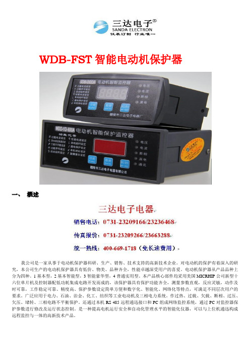
WDB-FST智能电动机保护器一、概述我公司是一家从事于电动机保护器科研、生产、销售、技术支持的高新技术企业。
对电动机的保护有着深入的研究,本公司生产的电动机保护器具有低价、物美、品种齐全,性能卓越深受用户的喜爱。
电动机保护器从产品品种上分为四种。
1基本型,2基本智能型,3智能豪华型,4普通实用型。
本产品核心部件均采用美国MICRHIP公司新型十六位单片机及控制器配低功耗集成电路开发而成的,该保护器具有保护功能齐全,测量参数直观,反应灵敏,动作及时可靠,工作稳定可靠、精度高、保护参数设定简单方便和数字化、智能化、网络化等特点,可满足不同层次用户的要求。
广泛应用于电力、石油、治金、化工、纺织等工业电动机及三相电力系统。
作过热、过载、欠载、断相、过压、欠压、堵转、三相电路不平衡保护。
还通过本机RS-485远程通迅接口和PC组成网络监控系统,通过PC对监控器保护参数进行修改及运行状态控制。
是一种提高电机运行安全和自动化管理水平的智能化仪器,可以与上位机通迅构成远程监控与一体的高新技术产品。
二、主要特点采用先进的微机技术与高性能的集成芯片,整机功能强大、性能优越。
测试精度高,线性度好,分辨率高,整机抗干扰能力强,保护动作可靠。
三相电流值,电压值及各类故障代号,显示于LED上、直观清晰。
稳定性好,长期工作无须维护。
采用E2PROM存储技术,实现参数设定,掉电后设定参数仍保存下来,勿须再设定。
一机多用,可取代传统的电流互感器、电流表、电压表、热继电器和时间继电器等。
配有RS485串行数字接口,便于上位机(PC)进行数字通迅。
三、主要功能保护功能:除了具有通用的保护功能外,还有自启动、通迅启动和关闭,且欠流、过压、欠压、三相电流不平衡、自启动等功能用户可取可舍。
设置功能:智能型有设置键、数据键和移位键,当设置超范围会提醒用户重新设置,避免误动作。
基本型通过拨码或电位电器设定。
报警功能:当电动机过流灯闪烁报警,过流倍数越大,闪烁越快,或用保护器的接点外置报警器显示功能:保护器通电后按设置键显示整电电流值,按数据键显示三相电流值。
- 1、下载文档前请自行甄别文档内容的完整性,平台不提供额外的编辑、内容补充、找答案等附加服务。
- 2、"仅部分预览"的文档,不可在线预览部分如存在完整性等问题,可反馈申请退款(可完整预览的文档不适用该条件!)。
- 3、如文档侵犯您的权益,请联系客服反馈,我们会尽快为您处理(人工客服工作时间:9:00-18:30)。
WDB电动机智能监控器使用说明书一、概述WDB系列电动机智能型电动机保护器,是一种提高电机运行安全和自动化管理水平的智能化仪器,核心采用美国MICROCHIP公司的微机控制器配低功耗集成电路开发而成的。
该保护器具有保护功能齐全,测量参数直观,反应灵敏,动作及时可靠,可以与上位机通讯构成远程监控于一体的高新技术产品。
广泛应用于石油、化工、煤炭、冶金、电力、钢铁、水泥、矿山、轻工、纺织等行业低压电动机保护及远程监控理想的产品。
二、特点1、采用微机技术和高性能低功耗电路,运算高速,性能稳定。
2、整机模块化结构,卡式电流传感器,体积小,安装方便。
也可分体安装,主体外形尺寸按照国际仪表装置标准。
3、采用数字处理技术,测量精度高,线性度好,对故障判断速度快,精确可靠。
4、高清晰宽温带背光LCD显示,设置参数与测量及故障记录直观方便。
5、可以与计算机通讯构成远程监控于一体的电机保护网络。
6、一机多用,可取代电流表,电流变送器,热继电器,漏电继电器,电压表。
三、适用范围及使用条件1、380V AC,660V AC三相异步电动机,馈线电路保护。
2、保护器供电电压;220V AC,380V AC、50HZ。
3、外型结构:整体与分体两种形式,分体安装距离≤5米。
4、环境温度:-30℃~+65℃,相对湿度≤90%。
5、使用环境:无足以腐蚀金属和破坏绝缘性能气体的环境。
6、安装在无剧烈震动冲击,强磁场干扰场所和雨雪侵袭的地方。
四、主要功能1、设定功能:额定电流、保护电流曲线、启动时间、三相不平衡、堵转倍数、漏电电流值、超欠电压值、通讯地址、保护器上电电机自起动时间。
2、保护功能:过流、堵转、三相不平衡、短路、漏电、断相、超欠压。
3、显示功能:A、B、C三相电流、漏电电流、工作电压、保护动作故障数据及故障记录、设置参数。
4、远传功能:具有4-20mA标准电流输出信号,20mA对应设定的额定电流值。
5、通讯功能:通过RS485串行通讯与计算机可构成256台保护器常规保护控制网络。
远程数据设定及显示报警,远程电动机启动,停止控制等。
6、追忆功能:可存储近期电机所发生的三次故障原因,并可按数字键取出最后一次电机发生的故障代号,再按一次显示前一次故障代号。
五、主要技术指标1、测试范围1.1 A、B、C三相电流:0—999A。
1.2 漏电流:0—999MA。
2、测量精度:1.5 级(I≤Ie额定电流)。
3、保护触点容量:常开AC250/6A,常闭AC250/6A。
4、启动时间整定范围:1~ 99S,在启动时间内,对断相、漏电、短路、不平衡进行保护(默认值为10S)。
5、堵转保护:当三相电流均达到或超过整定值的堵转电流时,动作时间≤0.5S(默认值为4Ie)。
6、短路保护:任意一相电流均达到或超过8Ie电流时,动作时间≤0.2S。
7、断相保护:任意一相断相时,动作时间≤2S。
8、不平衡保护:当三相电流中任意二相电流差比值≥不平衡系数,动作时间≤2S(默认值为60%)。
9、漏电保护;当电机漏电电流≥漏电流整定值,动作时间≤0.2S(默认值为50MA)。
10、过流保护:当电机的电流≥1.2Ie时,保护器按反时过流保护,动作时间见图一(默认值为1)。
11、过压保护:工作电压≥过压电压整定值,动作时间≤5S。
12、欠压保护:工作电压≤欠压电压整定值,动作时间≤10S。
13、4~ 20MA电流输出精度:0.3%F.S(20MA对应额定值)。
Iw/Ie 设定值动作时间(秒)≥1.2≥1.31≥1.38≥1.50≥2.0≥3.012345604836853120967220107180144120302014240192168403020300220200604025注:表中Iw为工作电流,Ie为额定电流。
图一六、操作说明及显示1、按键说明设置键:电机未运行或故障时,按此键进入保护参数设置状态。
见图二操作顺序 显示内容 代号定义 设定范围按一次设置键二按次设置键按三次设置键按四次设置键按五次设置键按六次设置键按七次设置键按八次设置键按九次设置键按十次设置键ACLqsPEL×LnUdq设置应在规格范围内设置1min~5min额定电流代号电流设定值过流时间曲线代号过流时间设定值电机启动时间代号启动间时设定值三相不平衡代号百分比设定值电机堵转代号Ie陪数设定值漏电代号漏电电流设定值欠电压代号欠电压设定值过电压代号过电压设定值通讯地址代号通讯地址设定值上电电机自起动代号自起动时间设定值1~990~100%0~2551~999S0为关闭自起动4-8倍1mA-999mA设定应在额定电压的范围内120%设定应在额定电压的范围内80%图二移位键:设置状态下选择设置的字位(该字位闪烁)。
数据键:设置状态下对应闪烁字位数每按一次加1。
复位键:在设置状态下按此键退出设置状态并确认设置值,保护动作后按此键保护器复位。
2、运行操作2.1 当电机运行时按设置键无效,当电机未运行或故障时按设置键修改设定值和查寻设定值。
2.2 运行时按移位键显示一次电压值和漏电电流值,如配合复位键可定位显示电压值和漏电电流值。
2.3 运行时按数据键可查寻最近3次故障记录。
2.4 运行时按复位键一次可定位显示当前显示状态,按复位键二次正常轮流显示A、B、C三相电流值。
3、当上位机与保护器正常通讯,面板通讯指示灯闪烁。
4、故障显示当电机运行存在故障时,保护器故障指示灯闪烁,达到设定技术指标时保护器动作,故障指示灯常亮,LCD首2位或首位指示相应故障代号(见图三)。
故障排除后按复位键保护器正常启动,按数据键可查寻最近3次故障记录。
A×××显示内容 定 义 复位方式过流动作代号过流动作值堵转代号断相代号不平衡代号过压代号过压动作值欠压代号欠压动作值短路代号漏电代号漏电电流值按复位键停电复位EP××××××d按复位键按复位键按复位键按复位键按复位键按复位键×××图三七、外型结构及安装尺寸、接线 (一)结构及安装尺寸93+0.545+0.5开孔尺寸11210072分体连接线小于5米202396931121006338.521.57481304548967040219345472 4.5600.2±102654450704互感器B449132945电位器连接器插头说明:适用于配在1A 、10A 、30A 、50A 、100A 、200A 规格漏电零序互感器。
互感器B90154.5939012380411094.50.2±电位器连接器插头13927432 - 4.5说明:适用于配在400A 、600A 规格漏电零序互感器(二)接线方法 1、一次接线1A 10A 50A 100A 200A 、、、、规格一次穿过监控器注:1A规格电机低于1K W,主回路穿过保护器需 绕10匝数。
400A 600A 5A 5、规格一次穿进变比为的电流互感器,互感器出线端进入保护器绕匝。
2、二次接线配合()一般接线图380v ~×L1L 2L3NFUK ME-K ME-K M135246J1J2M3~FUA100×L1L2L3NF UF U K ME-K ME -K M135246J1J2M3~A100配合()一般接线图220v ~JD B -MDJD B -MDK M135246J1J 278L1L 2L 3NFUFU×A KME-M3~配合()漏电保护接线图220v ~100L1L2L3NFU FUKMA M3~135246J1J2E -E-K M通讯接口910配()通讯接口及通讯启动接线图220v ~100J DB -M DJ DB-M DJ DB -M DL1L 2L 3NF U F UA 100K M K M135246J 1J298×E-E-107M3~RS485通讯接口分体()一带漏电保护、通讯接口接线图220v ~L 1L 2L3NFUFUK M×J 1J 2135246A 100M3~K MK ME-E -分体()一般接线图220v ~JD B -MDJD B -MDL 1L 2L 3K M A 100M3~K M135246J 1J 2×E-E-FUFUN分体()配互感器一般接线图220v ~L 1L2L 3KMNFUF UE-135246J1J298107K ME-K M×M3~配()通讯电流互感器,漏电保护通讯接口接线图220v ~JD B -MDJ DB -M DL1L2L 3K MN F U FUM 3~A 100135246J1J298107K ME-分体()配互感器、漏电保护、通讯接口及通讯启动接线图220v ~K MNM3~A 100135246J1J 298107K ME -分体()配互感器、漏电保护、通讯接口接线图220v ~×J DB -M DJD B -MD~4-20m A电流输出KMM3~A 100135246J1J2L 1L 2L3FUFUK ME-E-×整体()带电流输出接线图220v NF UFUA 100L1L2L 3K MM3~135246J1J2K ME -E -×4-20 mA电流输出分体()带电流输出接线图220v ~J DB -M DJD B -M D100L1L2L3K MKM135246J1J298×E-E -107FUFU M3~4-20 mA 电流输出整体()配互感器带漏电保护及电流输出接线图220v ~L1L2L3MFUFUA 100M3~135246J1J298107K ME-E -4-20 mA 电流输出×整体()配互感器带漏电保护及电流输出接线图220v ~NJDB -MD注意事项1、保护器安装接线时,应接各接线端子用途正确连接。
a 、01 02端子;电源(AC220V 、380V )输入、应接自一次主回路的空气开关前端或专用电源。
b 、03 04端子:保护出口J1(常闭)。
c 、05 06端子:保护出口J2(常开)或自起动(用户自选其一)。
d 、07 08端子:漏电保护传感器输入(K1、K2)。
e 、09 10端子:RS485通讯规约或4~20MA 电流输出。
2、保护器的工作电源应接控制回路上,注意标称电压与实际电压应相符。
3、各项保护设定值应正确无误,不用的选项应放弃设定。
4、根据电动机的额定电流值,选择相应电流规格的保护器。
5、当三相电缆线可直接穿过保护器的三相穿线孔时,可不拆卡式电流传感器;若不能直接穿过保护器的三相穿线孔时,可把卡式电流传感器拆成两半,再把电缆线卡入式电流传感器内,然后把卡式电流传感器组合成一体,并把固定螺丝扭紧。