迅达电梯300P资料
迅达300P_MRL电路图-10

平层指示灯 1/2黑 3绿 4黄 5棕 6粉红
门跨接触点
机房急停开关 井道门跨接开关
门跨继电器 1绿棕 2白绿 3棕 4白 5灰 6粉红
轿顶编码器
轿顶检修: 1.+24V.公用线 2.JREC.检修开关 3/5.DREC-U/D.慢上/下按钮 4.JHC.检修急停开关
曳引机马达
曳引机编码器
主接触器
电梯控制电源 应急电池
轿厢照明
轿厢风扇
井道照明
KWS:井道维修入口 JHM1:机房急停 KHA:盘车手轮 KLSG:爬梯急停 KSSBV:涨紧轮开关 JHSG1:爬梯急停开关 JHSG:底坑急停开关 KPG:对重缓冲器开关 KP:轿厢缓冲器开关 KNE-D:下极限开关 KBV:限速器开关 KNE-U:上极限开关 KF:安全钳开关 KNA:安全窗开关 JHCT:轿门停止 2.JHCT:门机急停 KTC:轿门锁开关 2KTC:2轿门锁开关 KTS:厅门锁开关 KV:厅门上锁开关 KWL:检修开关紧锁装置
抱闸板
安全钳开关
井道编码器
门机
轿厢风扇 轿厢照明
井道编码器
控制柜
安全/门锁
轿顶接线箱
LED:BRK-OP 运行时:灭 停止时:亮 抱闸制动器
3.ST-O开门信号 4.ST-S关门信号 5.KSKB力限开关 6.KET-O开关到位 7.KET-S关门到位 8.KTHMT门机热保护 9.VRVRT强迫关门 2.0V公用线
轿门锁开关 门机急停开关
门机变频记次器
KL-V:满载开关(080%) KL-X:超载开关(100%) KL-M:轻载开关(020%)
司机直驶按钮 司机开关
司机运行上、下 司机运行
轿厢风扇开关 轿厢照明开关 轿厢保留停靠开关 轿厢保留运行开关
迅达电梯300P电梯符号说明

注解 轿厢热敏电阻 退出服务灯热敏开关 机房热敏开关 电磁制动器的热敏开关 轿厢电源装置的热敏开关 群控电源的热敏开关 电梯电源的热敏开关 群控印板的热敏开关 控制的热敏开关 驱动控制的热敏开关 安全回路的热敏开关 入口的热敏开关 梯群入口的热敏开关 门的热敏开关 匹配变压器的热敏开关 匹配变压器的散热器的热敏开关 电磁制动器的匹配变压器开关 应急电源的变压器热敏开关 上行高峰矢量程序匹配变压器的热敏开关 中央控制器的匹配变压器的热敏开关 轿厢操纵盘内热敏开关 退出服务灯变压器热敏开关 应急电源变压器复位热77 78 79 80 81 82 83 84 85 86 87 88 89 90 91 92 93 94 95 96 97 98 99 100
符号 JTHC JTHLAB JTHM JTHMGB JTHNGC JTHNGG JTHNGL JTHPG JTHS JTHSA JTHSK JTHSZ JTHSZG JTHT JTHTA JTHTAH JTHTAMGB JTHTANS JTHTASPV JTHTAX JTHTC JTHTLA B JTHTNORS JTHTUV
注解 安装运行开关 应急控制开关 急停开关 紧急防盗服务开关 火警开关 火警释放开关 火警停*开关 应急电源操作(释放)开关 优先运行开关 检修开关 轿厢检修开关 检修开关 轿门检修开关 对接运行开关 复位控制开关 保留运行开关 轿厢保留运行开关 机房保留运行开关 轿厢停*保留开关 控制开关 搬运工/银行控制开关 机房照明控制开关 轿厢召唤堵塞开关 群控召唤堵塞开关 第 X 层轿厢召唤堵塞开关 机房内层站召唤堵塞开关 层站堵塞开关 开门堵塞开关 关门堵塞开关 入口堵塞开关 电源保安服务开关 厅门锁跨接开关 厅门锁跨接开关 开门开关 驱动的热敏开关 控制柜热敏开关 WITTUR 门机电源开关 制动热敏电阻
迅达300p手册_05
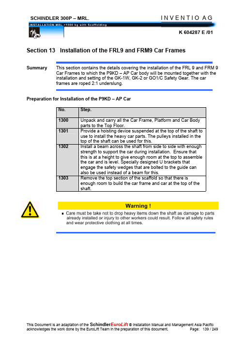
Section 13 Installation of the FRL9 and FRM9 Car FramesSummaryInstallation of the FRL9 or FRM9 Car FrameNo. Step.1304 Place the safety gear onto the support beam or U brackets,one set on each guide rail. Push the safety wedges up toengage the safety.1305 Hoist up the bottom yoke (beam) and place onto the safetygear and bolt on to the safety gear with the bolts supplied.Before tightening the fixing bolts ensure that the bottom beamis level.1306 Position the car frame uprights one on either side and boltthese to the bottom beam with the four M12X30 bolts withwashers provided and the plates with nuts welded to them.Before tightening these bolts ensure that the uprights areplumb.1307 Hoist the top yoke (crosshead) up to the top of the uprightsensuring that the governor arm is located on the side thegovernor is situated. Bolt the crosshead in position with thefour M12X30 bolts with lock washers and plates with nutswelded that are provided. Before tightening these boltsensure that the crosshead is level. See Figure 1. Below forFRL9 Car Frame and Figure 2 for FRM9 Car Frame details.1308 Lift the car frame up off the support beam with the hoistingdevice so that the bottom sliding car shoes can be fitted.Bolt these in position and before tightening these ensure thatgap between the top plate of the safety and the guide rail isequal on both sides. Also that the shoes are parallel and thatthere is a 2 mm side to side gap between the guide shoe andthe rail. The safety jaws should also be equidistant from therail on either side front to back.1309 Fit the sliding shoes to the crosshead and bolt these inposition. Before tightening ensure that the crosshead iscentral between the guides both side to side as well as frontto back. There should be a 2 mm side to side float in theguide shoes and they should be parallel.Hoist up the bottom yoke (beam) and place onto the safety gearSetting the Safety GearNo.Step. 1310Install the safety activating rods and screw these into the safety gear jaws. Fit the adjustment tube over the pull rods. Release the fixing bracket of the tension spring and attach the tension spring. Turn the fixing bracket back and bolt into position. adjust the rods to lift the jaws up 2mm on the GK-1W and GK-2 Safety and to give a 0,5mm gap below the jaws to the carrier on the GO1-C Safety. Use adjustment screw [a] on the GO1 – C to provide 2,5 mm gap on either side between the guide rail and the safety jaws [2].1311Fit the Governor activating arm onto the rod provided and knock the pin into clamping sleeve. Adjust dimension F according to the table below. Also ensure that the distance from the arm to the center of the guide is 280 mm.1312Lift or lower the car frame to the correct position from the top floor level to fit the main ropes, taking the distance the counterweight is situated above the counterweight buffer. 1313Lift the car up 50 mm and pull in the safety gear. Ensure that the car pawls level and that the safety gear is well applied. Check the distance to the top floor again and if incorrect carry out the operation again until correct. Remember to allow the HKB distance (normally 105 mm) plus car floor finish for the platform height above the sling bottom beam.Settings type GK1 – W Safety Gear. Settings type GO1 – C Safety Gear.Adjustment of dimension F.Tolerance in mm.Safety Gear Type. Adjusting dimensionsF in mm.GK1-W 33GK-2 33 ± 1,5GO1-C 60Fitting the Trailing Cable and Compensation Hitches:No. Step.1314 Fit the Trailing Cable Hitch and the Compensating ChainHitch to the bottom yoke in the correct positions.Fitting the Underslung Sheaves.No. Step.1315 Move the underslung sheave assembly into the shaft belowthe car frame and lift up to the welded top hat isolation frameon the side of the car that the ropes are to be situated.1316 Bolt the sheave assembly in position on the top hat section.1317 Before tightening the bolts ensure that the sheaves are plumband that they are free and turn easily.FRL9 Car Frame (Figure 1)FRM9 Car Frame (Figure2)Installation of Safety Gear, Guide Shoe and Automatic Guide Lubricator:Guide Shoe B029D on Up YokeGuide Shoe B029D with Lubricator (with G01-C)No. Type NameGear1 GK1-W Safety2 B 029D Guide Shoe3 --- Automatic Guide LubricatorGuide Shoe B029D with Lubricator (with GK1-W)No. Type NameGear1 GK1-W Safety2 B 029D Guide Shoe3 --- Automatic Guide LubricatorSelf-Engaging Actuating Mechanism for Car Sling :1. Overview of Self-Engaging Actuating Mechanism2. Installation of Self-Engaging Actuating MechanismNo. Step1318 Remove old governor lever and old governor lever stopper. And also remove the tension spring on the other side of the car sling.1319 Fix the new governor lever stopper [1] onto the up-yoke of car sling with the old four screws M 12 , washers and nuts .1320 Dill two holes on the up-yoke of car sling according to the holes position[16] in part [1].1321 Fix the governor lever [2] into the old shaft with the two new pins [8,9] . 1322 Tighten the bolt [10] with the governor lever by split pin [11] .1323 Fix the tension spring [4] into the bent eye bolt.1324 Fix and adjust the retaining spring [3] to make sure the lever end into the center of the retaining spring.1325 Adjust the limiter screw to set the dimension 33 ± 1.5 .Fixation of Travelling Cable and Compensating chain:Bracket Fixing for Travelling CableSection 14 Installation of the Main Traction Ropes and Governor Rope Summary This section contains the details covering the installation of theMain Traction and Governor Ropes. The Main ropes used the elevator Schindler300P-MRL have wedge type suspension rope connections with or without springfor diameter rope 10 mm (Z 459116) and are set out in document K 602488Traction rope - Mat. No. 462158.Rope for overspeed governor - Mat. No. 402024.Handling Ropes:Installation of the Main Traction Ropes.No. Step.1400 Start installation at the top of the shaft. Remove the ropeguard from the machine.1401 Place the rubber pad [2] and the steel rope plate [3] on thetop of the counterweight suspension plate.1402 Taking care not to damage the ropes wind the ropes throughthe car suspension sheave, then over the machine tractionsheave and let the rope down the shaft to the top of thecounterweight.1403 Wind the rope through the counterweight sheave and using ahemp rope hoist the rope to the top of the shaft.1404 Fit the rope end [4] on the counterweight end. Push the ropeend through the counterweight suspension plate, rubber pad[2] and steel plate [3] and fit the washers and nuts [5].1405 Judge the amount of rope needed and fit the car rope end.Pull the ropes tight starting from the counterweight side andPush the rope end through the car suspension plate. Fit thespring, washers and nuts. If necessary pull up any slack byremoving the end and redoing the fitting of the rope end.1406 Set out below is a diagram showing which holes in the Carand Counterweight Suspension Plates to use and whichgroove on the machine. Always start inserting the ropes ontothe sheave groove nearest the hoistway wall first and workingtoward the middle of the shaft with each next rope.1407 Carry out steps 1402 to 1406 for each rope ensuring that theropes are not twisted and that they are of similar length.1408 Lift up the car frame and take out the safety gear. With thecar frame hanging on the ropes check the tensions.Traction sheave and diverter pulleys with 5 and 7 grooves.C = Center LineNumber of Ropes Pulley Groove Traction grooves sheave number.Number 1 2 3 4 5 6 712 X3 3 X4 X51 X2 X4 34 X5 X1 X2 X5 3 X4 X5 X1 X2 X3 X6 45 X6 X7 X1 X2 X3 X7 4 X5 X6 X7 XCar- and Counterweight suspension pointC = Center lineNumber of Ropes Hole Number in Suspension Plate.1 2 3 4 5 6 73 X X X4 X X X X5 X X X X X6 X X X X X X7 X X X X X X X Six steps in fitting Rope Ends.Step No. Work Done:1 Insert the rope ends into the suspension plate. Pass therope through the first rope end and take up all the slack.2 Thread the rope end back through the front side of thewedge clamp body, leaving just a loop to install the wedge.3 Insert the wedge into the loop.4 While pulling up on the hoist rope to keep it taught, pulldown on the loose end with a quick pull until the rope loop isseated in the wedge correctly.5 Install all the other ropes this way and check that the ropesare similarly tensioned. If any rope is tighter or slacker thanthe others redo the rope wedge. Once all ropes similar withthe nuts at the same height on the rope bolts let the carhang on the ropes6 Check the rope tensions and adjust using the nuts on therope bolts to get equal tensions. Remember to hold thewedge clamp body to stop rotation.Rope End Installation Procedure.Rope End Clamp. Rope End Bolt with Clamp Fitted.Fit the Rope End ClampsNo. Step1409 Fit the rope end Clamps 20 mm from the bottom of the rope end. Themaximum the balance of the rope can be is 80 mm.Fit the Rope Retaining Guard and Sheave Cover.No. Step.1410 Fit the Rope Retaining Guards [3] and adjust to giveminimum clearance. Refit the Traction Sheave ProtectionCover [1] with the bolts, washers and nuts [2].Ropes.CounterweightCarRopes.Fitting the Anti Spin Ropes.No. Step.1411 Run the anti spin rope through the rope end wedge bolts asshown in the diagram above and fit a crosby clip. This is doneto stop the rope ends from rotating and unwinding the ropes.。
迅达电梯300P Word 文档

资料News错码含义错码含义错码含义错码含义001 正常运行停止 042 下端站 KSE 偏低 083 无 24 电源 619 速度参考值警告002 MC (微处理机)异常 043 下端站 KSE 偏高 084 DMS 损坏 620 电机控制超时003 停止时无 KSE 044 KSE 的距离较高 085 LM 通讯中断 621 UART 接受失败004 非法移动 045 无顶层 086 RUET 故障 622 消息源故障005 停止时 SH 吸合 046 顶层错误 087 RTSC 故障 623 消息长度错误006 停止时 SB 吸合 047 再平层错误 088 编码器故障 624 接受状态错误007 SH 故障 048 089 运行时间过长 625 发送状态错误008 SB 故障 049 OTP/ 层楼错误 090 停止反转故障 626 EPROM 检验失败009 KB 故障 050 软件错误 091 SMBP 故障 627 RAM 故障010 FC 故障 051 零参数 092 IVXVF--HW 故障 628 电池故障011 FC 阻断 052 CTP 溢出 093 ACCESS 按钮开关 629 RAM 校验失败012 方向错误 053 通讯中断 094 门触点 630 看门狗故障013 超速 054 PTC 校验数据 095 ESTL 超速 631 传送错误014 速度过低 055 PVF 通讯中断 096 ESTL 转接错误 632 安全回路开015 无向下目标 056 轿厢不停 097 ESTL 设备错误 633 HW 编码警告016 无向上目标 057 PVF 不停 098 通讯总线错误 634 矢量异常017 KSE 过速 058 SH 不停 099 RSX 故障 635 接触器超时018 无下端站 KSE 059 单次复位 100 RFE 故障 636 驱动板电源故障019 无上端站 KSE 060 双次复位 101 RTRT 故障 637 制动电阻过热020 位置丢失 061 RSE1 故障 102 RKUET 故障021 更高优先坏 062 RSE2 故障022 标志码清除 063 RSE3 故障023 JHC 被按下 064 PHS 故障 600 禁止启动024 JHC1 被按下 065 ----------------- 601 禁止再启动025 JHSG 被按下 066 无响应 602 过热026 JHR 被按下 067 XUET 故障 603 SW 警告027 JHM 被按下 068 SGRB 故障 604 DL 过压触发028 电机过热 069 SBNH 故障 605 DL 过压029 运行中断 070 SW 警告 606 DC 电压过低030 新运行中断 071 SW 错误 607 控制硬件命令错误031 准备新的目的地 072 110V 安全回路 608 DC 环充电失败032 准备撤消目的地 073 SPT 安全回路 609 DC 环放电失败033 接受新的目的地 074 KNE 安全回路 610 电流环不正常034 SH 接触器超时 075 RTS 安全回路 611 关闭电流环失败035 FC 接触器超时 076 运行结束安全回路 612 输入接触器故障036 启动不正常 077 LM 印板错误 613 充电接触器故障037 轿厢平层 078 LM 未调试 614 电流误差警告038 未知层站 079 TOPT 光耦故障 615 SW 编码警告039 未确定运行方向 080 PVF 过热 616 过流警告040 学习运行时不在 PHS 位置 081 速度编码器故障 617 过速警告041 脉冲发生器参数错误 082 无 12V 电源 618 启动方向错误在我接触过的系统中,奔克BP系列控制系统应该说算是比较好的,大量的功能,稳定的可*性,都无可挑剔。
迅达300p-mrl电梯建议保养程序
D S S S十二月十一月C S S S 十月 S S S SB S S S九月S S S S 八月A S S S 七月D S S S 六月C S S S 五月四月 S S S S三月 B S S S 二月 S S S S 一月A S S S 第一次保养 第二次保养 第三次保养 第四次保养 每周保养D S十二月十一月C S 十月 S SB S九月S S 八月A S 七月D S 六月C S 五月四月 S S三月 B S 二月 S S 一月A S第一次保养 第二次保养 每隔一周保养KG 应该执行的每隔一周或每周保养,是在12个月中A ,B ,C 或D 各执行两次,剩余的保养均为S 类型。
每隔一周或每周保养程序D十二月十一月C 十月 SB九月S 八月A 七月D 六月C 五月四月 S三月 B 二月 S 一月 A 保养/ 类型: 您的KG 应该制定一个在12个月中A ,B ,C 或D 各执行两次的月度性保养。
剩余其他月份的保养为S 类型。
月度性保养程序第四季度 S & D 类型S & C 类型第三季度S & B 类型第二季度第一季度 S & A 类型保养类型 成针对S300P 电梯的季度性保养,您的KG 应该有一个由S 类型和A ,B ,C 或D 中其中一种例行保养的组合。
季度性保养程序其他的保养将用S 类型保养来实施. A, B, C, D.类型 类型 类型 类型每隔12个月的周期应该尽量提供两次如下的全面保养:例行保养 建议保养程序迅达300P- MRL 无机房电梯建议保养程序12个月24个月12个月12个月60个月72个月12个月12个月每次保养12个月.4个月.每次保养每次保养12个月3个月.96个月12个月12个月12个月12个月最大20年最大30年每次保养通过运行计数器,在记录单上记录下电梯运行次数记录每一次保养情况 1. 若有厅门作为逃生门使用,必须检查这些厅门锁和安全触点4. 在使用电梯运行时检查曳引机是否发出超出范围的噪音,噪音通常来自井道.每次保养需检查下列项目并报告您在保养中所出现的任何问题给维保部门:检查任何倒车或超出平层的状况 在使用电梯运行时检查任何振动或超出范围的急拉颠簸.1. 2. 3. 检查散热装置,如果有一个或多个工作不正常需更换变频器Variodyne VF22BR and VF33BR 变频器保养流程(见 K604165 E).检查变频器的安装,电缆螺钉桩头 控制屏清洁 (用工具吹出灰尘) 1. 2. 3. Miconic MX – GC 控制器 (见 K 604108 C)检查控制器功能并听是否有过大的噪音, 检查继电器和接触器的运行以及是否有触点熔断的迹象. 检查门锁装置的控制器.紧固所有连接螺丝, 检查电子印板和接地情况更换控制器应急电池 (如提供,也包括DM236的电池)更换制动模块印板 检查编码器和齿型带的张紧情况 检查制动器松闸装置 1. 2. 3. 4. 5. 关门力限制器KSKB 的功能控制检查4.检查轿厢及平层驱动系统的状况和调整,包括齿形带,门刀,门导靴,滚轮,厅门自复位装置,电缆和地坎凹槽3. 检查调整厅轿门联锁,门锁装置和门锁滚轮检查厅轿门情况,门移动情况和卡锁功能是否完好V30门机 (见 K 603351 C) 厅门和轿门 1. 2. 轿厢和对重的悬挂:检查轿厢和对重的悬挂平台和固定点,悬挂绳和绳头,限速器悬挂支点,限速器,限速器钢丝绳,检查LMS(称重装置)悬挂点和LMS(称重装置)装置 (见 K604144 E).AC 无齿轮型PMS 230曳引机 (见 K604134 C). 对重放置在缓冲器上进行如下检查: 检查曳引机的整体情况, 制动器动作情况 (复位弹簧) 和曳引轮检查制动器衬套 检查曳引机支撑平台 减震垫 (如果损坏,更换) 检查编码器 检查绳轮槽, Bowden 电缆 (制动器打开和调整,若有需要可更换)更换风扇 (60,000小时使用后) 更换编码器 (200,000小时使用后)1. 2 3 4 5. 6. 7. 8. 此预防性保养程序作为A ,B ,C 或D 例行保养的一部分并且结合了维保技术资料所罗列的两次回召之间的保养任务。
迅达电梯300P电器元件代号说明-推荐下载

迅达电梯300P电器元件代号说明2010-03-19 22:12:48 作者:编辑整理序号符号注解1 JDCW-* 轿厢选层第X层的开关按钮(钥匙触点)2 JDCW-D* 轿厢选层第X层的下行开关按钮(钥匙触点)3 JDCW-U* 轿厢选层第X层的上行开关按钮(钥匙触点)4 JDE-* 厅站召唤第X层的开关按钮5 JDE-D* 厅站召唤第X层的下行开关按钮6 JDE-U* 厅站召唤第X层的上行开关按钮7 JDEV-* 第X层的楼层优先召唤钥匙按钮8 JDEVG-* 第X层的楼层优先召唤钥匙按钮(钥匙触点)9 JDFDC 轿厢按钮释放开关按钮(钥匙开关)10 JDNF-* 第X层的紧急召唤开关按钮(钥匙开关)11 JDNFG-* 第X层的楼层优先召唤钥匙按钮(钥匙开关)12 JDZHT-S 强迫关门停止开关按钮13 JFCC 编码的轿厢召唤释放开关14 JFEFNO 应急电源操作,救援运行释放开关15 JFEFNOM 应急电源操作,救援运行释放开关手册16 JFITS 安全回路对地漏电运行开关17 JH 主电源开关18 JHC 轿厢止动开关19 JHCT 轿门止动开关20 JHG 群控电源开关21 JHL 照明网络主开关22 JHM 机房急停开关23 JHM10 MICONIC 10 主电源开关24 JHNS 应急电源主开关25 JHR 滑轮间急停开关26 JHRF 对接运行的急停开关27 JHSG 地坑急停开关28 JHSG1 地坑急停开关(最低层站)29 JHTR 爬行控制的急停开关30 JHX 控制柜电源选择开关,中间部分31 JHZRS 目的层召唤控制电源开关32 JIB 运行开关33 JKL 读卡器开关34 JLAB 退出服务信号灯开关35 JLBS 井道照明开关36 JLC 轿厢照明开关37 JLF 学习运行开关38 JLI 司机控制开关39 JMOF 安装运行开关40 JNF 应急控制开关41 JNF-K 急停开关42 JNFE 紧急防盗服务开关43 JNFF 火警开关44 JNFF-F 火警释放开关45 JNFFP 火警停靠开关46 JNO 应急电源操作(释放)开关47 JPF 优先运行开关48 JRE 检修开关49 JREC 轿厢检修开关50 JRES 检修开关51 JRET 轿门检修开关52 JRF 对接运行开关53 JRH 复位控制开关54 JRV 保留运行开关55 JRVC 轿厢保留运行开关56 JRVM 机房保留运行开关57 JRVPC 轿厢停靠保留开关58 JS 控制开关59 JSBP 搬运工/银行控制开关60 JSLM 机房照明控制开关61 JSPC 轿厢召唤堵塞开关62 JSPCG 群控召唤堵塞开关63 JSPDC-* 第X层轿厢召唤堵塞开关64 JSPDEM 机房内层站召唤堵塞开关65 JSPS 层站堵塞开关66 JSPT-O 开门堵塞开关67 JSPT-S 关门堵塞开关68 JSPZS 入口堵塞开关69 JSSH 电源保安服务开关70 JSTUE1 厅门锁跨接开关96 JTHTAX 中央控制器的匹配变压器的热敏开关97 JTHTC 轿厢操纵盘内热敏开关98 JTHTLAB 退出服务灯变压器热敏开关99 JTHTNORS 应急电源变压器复位热敏开关100 JTHTUV 风扇电压变压器的热敏开关101 JTHX 中央控制器的热敏开关102 JTR 爬行控制开关103 JTTC 轿门隔离开关104 JUEKBF 火警跨接触点开关(火警探测器0 105 JUEKTS 门厅跨接触点开关106 JUEKTS-A 厅门跨接外触点开关107 JUEKTS-E 厅门跨接触点开关108 RET-O 开门限位触点继电器109 RET-S 关门限位触点继电器110 RF 对接运行继电器111 RFBE 楼层照明释放继电器112 RFE 启动运行继电器113 RFEF 撤离运行释放继电器114 RFF 停止运行继电器115 RFNO 应急电源操作继电器116 RFR 调节释放继电器117 RFT 强迫关门继电器118 RFUET 门跨接拖开继电器119 RH 第一速度主继电器120 RIB “在运行”继电器122 RICS- 轿厢位置编码器信息触点继电器123 RIDH1 保持按钮信息继电器124 RINFF 消防继电器125 RISPGC 内令存储阻断信息继电器126 RIT-S 关门信息继电器127 RKB 制动器监测继电器128 RKBI 涡流制动器监测继电器129 RKFMH 曳引电机磁场监测继电器130 RKMH 曳引电机监测继电器131 RKPH 相位监测继电器132 RKTHMH 曳引电机热保护监测继电器133 RKU (22V)电压监测继电器134 RKUET 门跨接监测继电器135 RKULC 轿内灯电源监测继电器136 RKUS 静态变换器监测继电器137 RKUSK 安全回路电压检查继电器138 RKV 门锁定检测继电器139 RKVZ 减速度检测继电器140 RL-A 安全板速度控制继电器141 RL-V 满载继电器142 RLAB “停止运行”信号灯继电器143 RLAB-A “停止运行”信号灯继电器(断开) 144 RLB 占用指示灯继电器145 RLBM 机房占用指示灯继电器147 RLC 轿内照明继电器148 RLC-A 轿内照明继电器(断开)149 RLI 司机控制继电器150 RLL-X 超载信号灯继电器151 RMGH 制动器磁性继电器152 RMGTC 轿内操纵盘磁铁继电器153 RMVE 电机风扇继电器154 RNF 紧急运行继电器155 RNFF 消防运行继电器156 RNI 向下运行继电器157 RNO 应急电源工作继电器158 RNT-O 正常开门继电器159 RNZK 门监控时间元件160 RPHT 门光电管继电器161 RPHTL 门安全触板光电继电器162 RPHTS 门光栅光电管继电器163 RR-D 下方向继电器164 2RR-D 第2入口侧下方向继电器165 RR-U 上方向继电器166 2RR-U 第2入口侧上方向继电器167 RRE 检修继电器168 RRE-A 检修继电器(断开)169 RRE-D 检修继电器向下170 RRE-U 检修继电器向上171 RRF 对靠运行继电器172 RRF-D 对靠运行继电器向下173 RRF-U 对靠运行继电器向上174 RRH 复位控制继电器175 RRSK 安全回路继电器176 RRV 保留继电器177 RS 控制印板178 RSA 追最终位置接触器179 RSE 井道端继电器180 RSE1 井道端继电器(第一速度) 181 RSE2 井道端继电器(第二速度) 182 RSE3 井道端继电器(第三速度) 183 RSIC SICURTRONIC继电器184 RSK 安全回路继电器185 RSM 故障信号继电器186 RSPE 阻断层楼继电器187 RSPE-* 第X层阻断继电器188 RSPFE 启动运行阻断继电器189 RSPNI 向下运行阻断继电器190 RSPNO 应急电源阻断继电器192 RSPTC 轿内操纵盘阻断辅助继电器193 RSPV 上高峰段继电器194 RSPZS 入口阻断继电器195 RSS 累加安全继电器196 RSS2 第二侧轿门累加继电器197 RST-NU 关门继电器(爬行)198 RST-O 关门继电器199 RST-S 开门继电器蜂200 RSUM 蜂鸣继电器201 RT-O 门继电器-断开202 RT-S 门继电器-关闭203 RTC 轿门继电器204 RTER 变压器激励继电器205 RTHU 变换装置热保护继电器206 RTR-D 爬行控制下行继电器207 RTR-U 爬行控制上行继电器208 RTRF 运行触发继电器209 RTRT 门触发继电器210 RTRU 变换器触发继电器211 RTS 厅门继电器212 RTS2 第2侧厅门继电器213 RTSC 厅轿门继电器214 RU 变换器继电器215 RU-E 变换器继电器(接通)216 RUEJHC1 轿门停止开关跨接继电器217 RUET 门跨接继电器218 RUET-A 门跨接继电器,断开219 RUET-E 门跨接继电器,接通220 RV 门锁定继电器221 RVEC 轿箱风扇继电器222 RVEC-A 轿箱风扇继电器,断开223 RVRT 门减速继电器224 RVZ 减速,停止继电器225 RY 星形连接继电器。
迅达300P_MRL图纸

力限开关
ቤተ መጻሕፍቲ ባይዱ
光幕
运行记次器
KL-V:满载开关(080%) KL-X:超载开关(100%) KL-M:轻载开关(020%)
司机直驶按钮 司机开关
司机运行上、下 司机运行
轿厢风扇开关 轿厢照明开关 轿厢保留停靠开关 轿厢保留运行开关
编码器
抱闸 抱闸
电动机 主机风扇
电动机热保护
曳引机马达
曳引机编码器
主接触器
抱闸接触器输出
曳引机冷却扇
LED:SB1 运行时:灭 停止时:亮
LED:ZSB 运行时:灭 停止时:亮
BCM420 2.Q B ID.NR.591506
LED:KB 运行时:灭 停止时:亮
LED:KB1 运行时:亮 停止时:灭
LED:SB 运行时:亮 停止时:灭
SB/SB1抱闸接触器
平层指示灯 1/2黑 3绿 4黄 5棕 6粉红
Generated by Foxit PDF Creator © Foxit Software 门跨接触点
机房急停开关 井道门跨接开关
门跨继电器 1绿棕 2白绿 3棕 4白 5灰 6粉红
轿顶编码器
轿顶检修: 1.+24V.公用线 2.JREC.检修开关 3/5.DREC-U/D.慢上/下按钮 4.JHC.检修急停开关
变频器 主板
抱闸板
安全钳开关
井道编码器
门机
轿厢风扇 轿厢照明
井道编码器
控制柜
安全/门锁
轿顶接线箱
ZSB抱闸节能接触器
LED:BRK-OP 运行时:灭 停止时:亮 抱闸制动器
3.ST-O开门信号 4.ST-S关门信号 5.KSKB力限开关 6.KET-O开关到位 7.KET-S关门到位 8.KTHMT门机热保护 9.VRVRT强迫关门 2.0V公用线
迅达电梯300P资料

迅达电梯资料错码含义错码含义错码含义错码含义001 正常运行停止042 下端站KSE 偏低083 无24 电源619 速度参考值警告002 MC (微处理机)异常043 下端站KSE 偏高084 DMS 损坏620 电机控制超时003 停止时无KSE 044 KSE 的距离较高085 LM 通讯中断621 UART 接受失败004 非法移动045 无顶层086 RUET 故障622 消息源故障005 停止时SH 吸合046 顶层错误087 RTSC 故障623 消息长度错误006 停止时SB 吸合047 再平层错误088 编码器故障624 接受状态错误007 SH 故障048 ?089 运行时间过长625 发送状态错误008 SB 故障049 OTP/ 层楼错误090 停止反转故障626 EPROM 检验失败009 KB 故障050 软件错误091 SMBP 故障627 RAM 故障010 FC 故障051 零参数092 IVX VF--HW 故障 628 电池故障011 FC 阻断052 CTP 溢出093 ACCESS 按钮开关629 RAM 校验失败012 方向错误053 通讯中断094 门触点630 看门狗故障013 超速054 PTC 校验数据095 ESTL 超速631 传送错误014 速度过低055 PVF 通讯中断096 ESTL 转接错误632 安全回路开015 无向下目标056 轿厢不停097 ESTL 设备错误633 HW 编码警告016 无向上目标057 PVF 不停098 通讯总线错误634 矢量异常017 KSE 过速058 SH 不停099 RSX故障635 接触器超时018 无下端站KSE 059 单次复位100 RFE 故障636 驱动板电源故障019 无上端站KSE 060 双次复位101 RTRT 故障637 制动电阻过热020 位置丢失061 RSE1 故障102 RKUET 故障021 更高优先坏062 RSE2 故障022 标志码清除063 RSE3 故障023 JHC 被按下064 PHS 故障600 禁止启动024 JHC1 被按下065 ----------------- 601 禁止再启动025 JHSG 被按下066 无响应602 过热026 JHR 被按下067 XUET 故障603 SW 警告027 JHM 被按下068 SGRB 故障604 DL 过压触发028 电机过热069 SBNH 故障605 DL 过压029 运行中断070 SW 警告606 DC 电压过低030 新运行中断071 SW 错误607 控制硬件命令错误031 准备新的目的地072 110V 安全回路608 DC 环充电失败032 准备撤消目的地073 SPT 安全回路609 DC 环放电失败033 接受新的目的地074 KNE 安全回路610 电流环不正常034 SH 接触器超时075 RTS 安全回路611 关闭电流环失败035 FC 接触器超时076 运行结束安全回路612 输入接触器故障036 启动不正常077 LM 印板错误613 充电接触器故障037 轿厢平层078 LM 未调试614 电流误差警告038 未知层站079 TOPT 光耦故障 615 SW 编码警告039 未确定运行方向080 PVF 过热616 过流警告040 学习运行时不在PHS 位置081 速度编码器故障617 过速警告041 脉冲发生器参数错误082 无12V 电源618 启动方向错误。
- 1、下载文档前请自行甄别文档内容的完整性,平台不提供额外的编辑、内容补充、找答案等附加服务。
- 2、"仅部分预览"的文档,不可在线预览部分如存在完整性等问题,可反馈申请退款(可完整预览的文档不适用该条件!)。
- 3、如文档侵犯您的权益,请联系客服反馈,我们会尽快为您处理(人工客服工作时间:9:00-18:30)。
迅达电梯资料
错码含义错码含义错码含义错码含义
001 正常运行停止042 下端站KSE 偏低083 无24 电源619 速度参考值警告002 M C (微处理机)异常043 下端站KSE 偏高084 D MS 损坏620 电机控制超时
003 停止时无KSE 044 K SE 的距离较高085 L M 通讯中断621 U ART 接受失败004 非法移动045 无顶层086 R UET 故障622 消息源故障
005 停止时SH 吸合046 顶层错误087 R TSC 故障623 消息长度错误
006 停止时SB 吸合047 再平层错误088 编码器故障624 接受状态错误
007 S H 故障048 ?089 运行时间过长625 发送状态错误
008 S B 故障049 O TP/ 层楼错误090 停止反转故障626 E PROM 检验失败009 K B 故障050 软件错误091 S MBP 故障627 R AM 故障
010 F C 故障051 零参数092 I VXVF--HW 故障628 电池故障
011 F C 阻断052 C TP 溢出093 A CCESS 按钮开关629 R AM 校验失败012 方向错误053 通讯中断094 门触点630 看门狗故障
013 超速054 P TC 校验数据095 E STL 超速631 传送错误
014 速度过低055 P VF 通讯中断096 E STL 转接错误632 安全回路开
015 无向下目标056 轿厢不停097 E STL 设备错误633 H W 编码警告016 无向上目标057 P VF 不停098 通讯总线错误634 矢量异常
017 K SE 过速058 S H 不停099 R SX 故障635 接触器超时
018 无下端站KSE 059 单次复位100 R FE 故障636 驱动板电源故障019 无上端站KSE 060 双次复位101 R TRT 故障637 制动电阻过热
020 位置丢失061 R SE1 故障102 R KUET 故障
021 更高优先坏062 R SE2 故障
022 标志码清除063 R SE3 故障
023 J HC 被按下064 P HS 故障600 禁止启动
024 J HC1 被按下065 ----------------- 601 禁止再启动
025 J HSG 被按下066 无响应602 过热
026 J HR 被按下067 X UET 故障603 S W 警告
027 J HM 被按下068 S GRB 故障604 D L 过压触发
028 电机过热069 S BNH 故障605 D L 过压
029 运行中断070 S W 警告606 D C 电压过低
030 新运行中断071 S W 错误607 控制硬件命令错误
031 准备新的目的地072 110V 安全回路608 D C 环充电失败
032 准备撤消目的地073 S PT 安全回路609 D C 环放电失败
033 接受新的目的地074 K NE 安全回路610 电流环不正常
034 S H 接触器超时075 R TS 安全回路611 关闭电流环失败
035 F C 接触器超时076 运行结束安全回路612 输入接触器故障
036 启动不正常077 L M 印板错误613 充电接触器故障
037 轿厢平层078 L M 未调试614 电流误差警告
038 未知层站079 T OPT 光耦故障615 S W 编码警告
039 未确定运行方向080 P VF 过热616 过流警告
040 学习运行时不在PHS 位置081 速度编码器故障617 过速警告
041 脉冲发生器参数错误082 无12V 电源618 启动方向错误。