音箱可靠性测试规范
音箱成品检验标准

东莞市金正数码科技有限公司检验标准注:1、同一项目后面所跟的内容须一一对应; 2、在缺陷内容与其所属缺陷级别栏作相应记号“0”;3、A表示严重缺陷; B表示重缺陷; C表示轻缺陷。
东莞市金正数码科技有限公司检验标准注:1、同一项目后面所跟的内容须一一对应; 2、在缺陷内容与其所属缺陷级别栏作相应记号“0”;3、A表示严重缺陷; B表示重缺陷; C表示轻缺陷。
东莞市金正数码科技有限公司检验标准注:1、同一项目后面所跟的内容须一一对应; 2、在缺陷内容与其所属缺陷级别栏作相应记号“0”;3、A表示严重缺陷; B表示重缺陷; C表示轻缺陷。
东莞市金正数码科技有限公司检验标准注:1、同一项目后面所跟的内容须一一对应; 2、在缺陷内容与其所属缺陷级别栏作相应记号“0”;3、A表示严重缺陷; B表示重缺陷; C表示轻缺陷。
东莞市金正数码科技有限公司检验标准注:1、同一项目后面所跟的内容须一一对应; 2、在缺陷内容与其所属缺陷级别栏作相应记号“0”;3、A表示严重缺陷; B表示重缺陷; C表示轻缺陷。
东莞市金正数码科技有限公司检验标准注:1、同一项目后面所跟的内容须一一对应; 2、在缺陷内容与其所属缺陷级别栏作相应记号“0”;3、A表示严重缺陷; B表示重缺陷; C表示轻缺陷。
东莞市金正数码科技有限公司检验标准注:1、同一项目后面所跟的内容须一一对应; 2、在缺陷内容与其所属缺陷级别栏作相应记号“0”;3、A表示严重缺陷; B表示重缺陷; C表示轻缺陷。
东莞市金正数码科技有限公司检验标准注:1、同一项目后面所跟的内容须一一对应; 2、在缺陷内容与其所属缺陷级别栏作相应记号“0”;3、A表示严重缺陷; B表示重缺陷; C表示轻缺陷东莞市金正数码科技有限公司检验标准注:1、同一项目后面所跟的内容须一一对应; 2、在缺陷内容与其所属缺陷级别栏作相应记号“0”;3、A表示严重缺陷; B表示重缺陷; C表示轻缺陷。
东莞市金正数码科技有限公司检验标准注:1、同一项目后面所跟的内容须一一对应; 2、在缺陷内容与其所属缺陷级别栏作相应记号“0”;3、A表示严重缺陷; B表示重缺陷; C表示轻缺陷。
音响检验标准
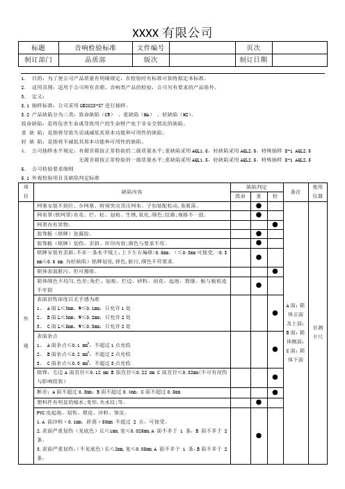
1. 目的:为了使公司产品质量有明确规定,在检验时有标准可依特拟定本标准。
2. 适用范围:适用于公司所有音箱、音响类产品的检验,公司另有要求的产品除外。
3. 定义:3.1 抽样标准:公司采用GB2828-87进行抽样。
3.2 产品缺陷分为三类:致命缺陷(CR)、重缺陷(MA)、轻缺陷(MI)。
致命缺陷:是将危害生命或导致用户的生命财产处于非安全情况的缺陷。
重缺陷:是指将导致失误或减低其原本功能和可用性的缺陷。
轻缺陷:是指将不减低其原本功能和可用性的缺陷。
4. 公司抽样水平规定:有源音箱按正常检验的二级质量水平;重缺陷采用AQL1.5,轻缺陷采用AQL2.5。
特殊抽样 S-1 AQL2.5无源音箱按正常检验的一级质量水平;重缺陷采用AQL1.5,轻缺陷采用AQL2.5。
特殊抽样 S-1 AQL2.5 5. 公司检验要求细则5.1 外观检验项目及缺陷判定标准5.2 结构检验要求:5.3 性能检验要求:5.4 附件检验要求A.遥控器:B.连接线材:线材外面无破损,标识清晰,材质与样品一致,连接后检查无 INT 或不通现象,接线埠无氧化,无变形,折迭试验后无断裂且无明显折痕,长度;颜色与要求一致。
包括线材的横截面积C.安装(连接)图:要求图文清晰,无模糊不清情况出现,图文无错漏。
纸质与样品要求一致,无脏污及其它不良,装箱后需做到整洁。
D.说明书、外箱印刷文字、条形码等有以下问题均为重缺陷:a、未按客人指定的语言文字生产.(如指定英文或俄文等).b、保修卡和注意窗体内容必须正确,文字清晰.c、产品说明书有严重错误,可能使用户不能正常操作,误操作d、产品说明书所述功能与实际不符者e、附件外观受损或脏。
E、电池:电压未达到额定电压为重缺陷。
F、附件中定位栓与支架中管定位孔不匹配为重缺陷G、其它:按客户要求及样品进行。
5.5 包装运输检验要求:跌落试验:每批产品随机抽取一到三台进行三边六面一角进行跌落,要求包装材料无破裂,整机在跌落后测试符合所有要求。
音箱检测标准
5台 外观,功能均正常
3台
包装、卡通无受损,主要部件无受 损,其它功能正常。
11.顷斜跌落试验
角度18°至20°,冲击力 2.0至2.8kg.
1台 各部件不能分离。
碰撞高度:30cm,
12.机械碰撞试验
测试基础:在混凝土地 面,每次四底面,工作状
态。
a.温度:20℃±1℃,湿
度60%±2%;
13.扬声器(系统) b.在额定功率范围内给扬
项目 外观
项目要求
测试方法及描述
缺陷描述
缺陷等级
1.箱体无色差、异 色、划伤、碰伤、 缩水、裂痕、披峰 、脱漆、龟裂、污 痕、变形、裂缝、 松动、漏气等。 在40W的日光灯
有明显的色差、划伤、碰伤、污 痕、变形等 缩水深于0.3mm,或者面积大于1 平方毫米,裂缝大于0.2mm 有裂痕、龟裂、脱漆、变形、棱 角不圆滑易伤手、松动、箱体漏 气等。
判定方法
a.温度:45℃±2℃,湿 度:60%±2%; b.时间:2小时关机,8小 时开机工作;无包装; c.额定电压±10%
3台
回到正常状态后,样机连续工作无 任何质量异常。
2.低温负荷试验
a.温度:2±2℃,湿度: 干燥条件; b.时间:2小时关机,5小 时开机工作,无包装; c.额定电压±10%
5mm小于8mm的不多于3条,深度以 MI
无手感为准.
正面:直径在0.25mm-0.5mm之 间,不多于1点。
MI
各侧面:直径在0.5-1mm之间, 不多于1点.
MI
直径在3mm以内,大于1mm小于 3mm不多于1点。
MI
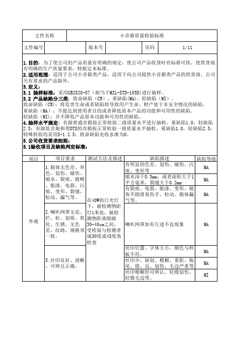
文件名称 文件编号
版本号
小音箱质量检验标准 页码
3/11
音响类产品检验标准
核定审核:制订:李志方1目的规范音响类产品的检验要求,为检验提供检验依据,以控制产品的质量。
2适用范围适用于产品来料.制程.出货生产音箱类产品的检验。
3 检验环境3.1 检验温度:25℃±10℃,相对湿度:45%~85%3.2 光照条件:在冷白荧光照射下,光源500-800Lux,距物品1米3.3 视角:视线与工件平齐,正负旋转45°3.4 视力要求:视力要求:≧0.8 (裸视或经矫正后)3.5检视时间和距离:4 缺陷等级定义4.1致命缺陷(CR):指对使用者或携带者的安全带来危害或违反相关安规之缺陷。
4.2严重缺陷(MA):不构成致命缺陷,但很可能造成故障,或对单位产品使用功能会严重降低,或严重影响产品形象之缺陷。
4.3轻微缺陷(MI):外观性缺陷,不构成致命或主要缺陷,不影响产品使用功能。
5 表面等级划分:AA面----公司LOGO及丝印区域。
A级面----正常使用时可以看到的面,如产品正面。
B级面----正常使用时看不到的表面及产品背面、底面及侧面。
6外观判定标准6.1常见外观缺陷判定表6.2 通用外观要求:6.2.1产品Logo区或丝印周边20mm以内不允许有任何明显的缺陷,不允许有印刷模糊、缺少笔画、漏印、印偏及色泽不均匀等现象。
6.2.2所有结构部品一律去锐边,锐角。
毛边、披锋控制在0.1mm以内。
6.2.3布网内音箱布网上不允许有纹路歪斜、断线及超过0.2mm的线头。
注:1.本标准如有与工程图纸/签样或客户提供资料相抵触的,则以后者为准。
2.本公司抽样标准采用美国军标MIL-STD-105E,功能性问题AC=0/RE=1,外观按AQLMAJ=0.4 MIN=1.5允收数量为准。
音箱检测标准

外露螺丝打花,不外露螺丝打花
且取不出,滑牙、漏打、错打、 MA
断裂、生锈等。
螺丝未打紧大于1圈小于3圈,只 有1颗。
MI
漏贴贴纸、贴错贴纸、破损起泡 、与美术资料不符、
MA
贴纸未平贴或者贴歪小于15度
MI
整机有脏污,但可擦干净,数量 少。
MI
走线错误、排线未打胶、打胶位
置不对、胶量不合理、元器件排 列不规范,碰脚、机内漏打螺丝
MA MA
防火材料。提供相关的试验报告
外观良好、丝印清晰,有规定相 关安全认证标识。
4.适配器
通电状况良好,输出电压、电流
符合要求并能带动机器工作,
MA
耐压、绝缘阻抗测试,提供相关 的测试报告.
文件名称 文件编号
小音箱可靠性试验方法及标准判定
版本号
页码
7/11
试验项目 1.高温负荷试验
试验条件
数量
判定方法
a.温度:45℃±2℃,湿 度:60%±2%; b.时间:2小时关机,8小 时开机工作;无包装; c.额定电压±10%
3台
回到正常状态后,样机连续工作无 任何质量异常。
2.低温负荷试验
a.温度:2±2℃,湿度: 干燥条件; b.时间:2小时关机,5小 时开机工作,无包装; c.额定电压±10%
按键与面板结合严重松动或者卡 死键,行程过短或过长与其它按 键手感不一致。 按键失灵、损坏、过松、过紧、 MA 明显变形、手感不好、有机械磨 擦声;控制按钮脱落、旋转扭旋 转不顺畅。
按规定接通产品要求的电压和频 率,打开电源开关,不可出现死机 、内部冒烟、开关机不可有冲击声 MA 、杂音等,产品有特殊要求按要求 检查:如延迟时间、记忆功能等。
音箱可靠性测试要求,以及品质控制
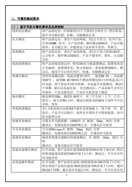
8
低温存储测试 高温存储测试
功能异常 关闭电源, 把产品放在温度-20度环境下24小时, 最后放在室 温2小时,测试后,不可以有任何功能异常 关闭电源, 把产品放在温度+60度环境下24小时, 最后放在室 温2小时,测试后,不可以有任何功能异常
12.2 蓝牙音响喷油及丝印要求 百格测试 在产品表面10*10mm范围,用刀切成1mm平方的小格子,用至 少25.4mm长的 3M 600型号胶粘贴在百格上面, 压紧, 然后用 135度及45度角度拉胶纸,拉下的时间在1秒内快速拉下, 同一胶件,应选择3-4个点做测试,拉下后,丝印面积需要保 持85%以上面积完好才合格 纸带摩擦测试 使用标准的测试仪器及 #7976 测试带, 测试环境湿度不超过 50%,喷油必须通过15周期 175克力的测试,测试后,表面不 应该有损坏及漏底。 化学测试 用90%的酒精滴在产品表面等2分钟,用白布抹去酒精,表面 不应该有任何掉色。 环境测试 存储测试样品在70度 90%的湿度下72小时表面不应该有任何 掉色或变化 盐雾测试 用5% 盐水,喷雾测试48小时,然后把样品放在室温1小时, 不需要清洁盐水,然后自然风干,查看表面部应该有生锈及 变色 13,安全性要求: 13.1, 产品的电池必须要有基本的安全测试认证报告:UN38.3, 如客户有需要, 需要提供客户的有关电池的安全测试报告, 供应商需要在来料检验时 提交有效的测试报告,这点在电池选料时做要求. 13.2, 在电路设计上,严格按照安全设计要求做, 1.1, 聚合物电池容量小于150mAh的, a, 输入部分串2.2欧姆电阻 b, 如果PCB 够大,再加上LDO电路(LDO电压值DC1.8V,普通封装) 1.2, 聚合物电池容量大于150mAh的, a, 输入部分接二极管保护 b, 如果PCB 够大,再加上LDO电路(LDO电压值DC1.8V,普通封装) 1.3, 对于电容式电池的产品,除了采用1.1 或 1.2的设计外,还要注意: a, 电池引脚加胶水覆盖,防止短路,供应商做好,开发打样机承认时注意 b, 取消滤波电容,防止电容被击穿短路发热 1.4, 头戴连接线及内部多股转接线换用内绝缘线,防止线互相短路导致发热 1.5, 取消Mic USB接副耳机功能
音箱检测标准
5台 功能正常、内部结构无变化、外面
100台 变化客户接受、产品表面温升不可 高于60℃。
批量性
a.温度:40℃±2℃,湿
7.恒定湿热检查
度:93%,无包装样机; b.时间:不通电48小时, 回复常温条件24小时后通
3台
回到常温后,样品能连续正常工作 且无任何质时异常。
电检查。适用木箱试产机
文件名称 文件编号
5台 外观,功能均正常
3台
包装、卡通无受损,主要部件无受 损,其它功能正常。
11.顷斜跌落试验
角度18°至20°,冲击力 2.0至2.8kg.
1台 各部件不能分离。
碰撞高度:30cm,
12.机械碰撞试验
测试基础:在混凝土地 面,每次四底面,工作状
态。
a.温度:20℃±1℃,湿
度60%±2%;
13.扬声器(系统) b.在额定功率范围内给扬
MA
率来提高音箱的响度。
音箱输出的声功率与输入的电功
率之比(即声—电转换的百分
MA
比)
线材外面无破损、标识清晰、材
质与样品一致、连接后检查有无
1.连接线材
INT、不通等现象,接线座无氧 化、无变形,弯折试验后无断残
MA
裂、弯折、功能正常,长度,颜
色、横截面与要求一致。
未按客人指定的语言文字或者内
2. 说明书、外包
高有效放声频率(50~ 16K)HZ或者(40~
MA
20K)HZ
音箱声压和相位与频率
7.频率响应
的相应关系,分贝值越 MA
小越好,说明失真越小
指向频率特性好的音箱就
8.指向频率特性
像日光灯,光线能够均匀 的散布到室内每一个角
音箱可靠性测试规范
HARMAN INTERNATIONALRELIABILITY TEST PLANforAUTOMOTIVE AUDIO SPEAKERharman consumer groupCentral Quality GroupRelease Date: 2/1/98 Revision Level: KRevision Level Date: 03/31/051.0 PurposeThe purpose of this test plan is to describe the environmental and functional performancerequirements to which the speaker will undergo in order to be validated. The intent of thevalidation program is to expose the speaker to an accelerated aging process.2.0 Test PlanThis test plan details the type of tests and the number of units required for each. The sample size outlined below may change depending on Reliability Target.2.1 Test ImplementationThe full qualification test program consists of the groups listed below. This is a parallel test sequence such that each group is run independently. This test plan must be performed on at least one member of a “Product Family”. The most complex or highest power model should be chosen.Full Qualification Test SequenceGroupQuantityDV PVTest Name Spec. Sect.No.Functional TestRequirementsA 2 6Life Cycle 5.1 4.4 and 4.5B 2 6Power Test 5.4 4.4 and 4.5UV Exposure Test 5.8Impact Test 5.5C 2 6Humidity Test 5.3 4.4 and 4.5Random Vibration Test 5.6 4.4 and 4.5D 2* 6 Packaging Test (ASTM) 5.7 4.4 and 4.5For Packages up to 150 lbs (ASTM4169)Handling (Drop), First Sequence 5.7.1 4.4 and 4.5Compression Test (Vehicle StackingAssurance Level II)5.7.2 4.4 and 4.5Loose Load Vibration 5.7.3 4.4 and 4.5Vehicle Vibration 5.7.4 4.4 and 4.5Handling (Drop), Second Sequence 5.7.5 4.4 and 4.5Temperature Test 5.2 4.4 and 4.5(1) For Master Pack Shipping Option (ifavailable)5.7.9Humidity Storage Test 5.7.9.1Loose Load Vibration 5.7.3VehicleVibration 5.7.4* If packaging is available.Note 1: Unless otherwise specified, all units shall be tested in the orientation that unit will be mounted in the car.Note 2: The performance limits of the units under test will be specified in the HCG approved Engineering Test Specification (ETS) [see Section 6].2.2 Abbreviated QualificationThe abbreviated test program consists of the groups listed below. This is a parallel test sequence such that each group is run independently. These tests must be performed on all members of a “Product Family” not subjected to the Full Qualification found in section 2.1.Abbreviated Qualification Test ScheduleGroupDV PV Test Name Spec. Sect.No.Functional TestRequirementsA 2 6Life Cycle 5.1 4.4 and 4.5B 2 6Power Test 5.4 4.4 and 4.5Handling Drop Test 5.5C 2* 6Packaging Test (ASTM) 5.7 4.4 and 4.5For Packages up to 150 lbs (ASTM4169)Handling (Drop), First Sequence 5.7.1 4.4 and 4.5Compression Test (Vehicle StackingAssurance Level II)5.7.2 4.4 and 4.5Loose Load Vibration 5.7.3 4.4 and 4.5Vehicle Vibration 5.7.4 4.4 and 4.5Handling (Drop), Second Sequence 5.7.5 4.4 and 4.5* If packaging is available.Note 1: Unless otherwise specified, all units shall be tested in the normal car mounting orientation.Note 2: The performance limits of the UUT will be specified in the Engineering Test Specification.3.0 Standard Test Conditions3.0.1 Signal SourceUnless otherwise specified, all tests shall be conducted with the Audio SignalGenerator/Amplifier output configured to be balanced, less than or equal to 50-ohm source impedance, and floating. The signal source GND shall be connected to the speaker PWRGND at the speaker.3.0.2 PositionUnless otherwise specified, the speaker shall meet all requirements in the “normal mounting position”. It is defined on the Product Specification as to the horizontal or vertical position of the mounting surface.3.0.3 Room TemperatureUnless otherwise specified, all measurements shall be made at room temperature. Roomtemperature is specified as 23o C +/-3o C.3.0.4 Frequency RangeThe frequency range is specified from the -3dB point at the upper and lower operating range of the driver. This range and the limits with in that range shall specified on the ProductSpecification.3.0.5 NoiseThe products are divided into three groups, full range (multi-element), mid-bass, and sub-woofer. The type of product shall be specified on the Product Specification.Full Range will use track 13 on the Car Audio Test Disc Version 2.0: IEC noise with acrest factor of 9dB.Mid-bass will use track 14 on the Car Audio Test Disc Version 2.0: a decade of pinknoise, 50 to 500Hz (-3dB points) 12dB slopes, with a crest factor of 9dB.Sub-woofer will use track 15 on the Car Audio Test Disc Version 2.0: a decade of pinknoise, 30 to 300Hz (-3dB points), 12dB slopes, with a crest factor of 9dB.3.0.6 Music SignalThe products are divided into two groups: 1) full range (multi-element) and mid-bass, 2) sub-woofer. The type of product shall be specified on the Product Specification.Full Range and Mid-bass – track 16 on the Car Audio Test Disc Version 2.0: “Beat It”by Michael JacksonSub-woofer – track 17 on the Car Audio Test Disc Version 2.0: “Crime Stories” by MCHammer4.0 Functional RequirementsFunctional requirements are to be tested in accordance with an HCG approved product engineering specification (ETS).4.0.1 PolarizationWith the driver face down and the terminal facing toward you the Product Specification shall identify the positive terminal, which shall be labeled Pin 1 or “+”. When a positive potential is applied to the positive terminal, the cone shall move outward from the basket producingpositive pressure.Ref. IEC 268-24.0.2 DC ResistanceEnsure that the test lead resistance is factored out of this measurement. Connect the test leads to the speaker and measure the resistance in ohms with an averaging ohmmeter to ensure that ambient noise levels do not produce an EMF at the meter yielding false resistance readings.The DCR shall be within the limits specified on the Product Specification.4.0.3 ImpedanceRigidly suspend the speaker from the motor structure in free air at least 50 cm from thenearest reflecting surface. Mounting means must be minimal in bulk such that the airmovement during testing is substantially unrestricted.Measure the deviation from the Reference Sample Speaker impedance at each of the definedfrequencies. The deviation at all frequencies shall be within the limits specified on the Product Specification.4.0.4 Frequency ResponseApply a stepped sine wave sweep or a Canetics signal over the specified frequency range,using the specified frequency spacing, with the specified bandwidth smoothing per theProduct Specification, and analyze the microphone output. Calibrate the measurement system to display the 1 Watt 1 Meter equivalent sensitivity based on Z nom as specified on the Product Specification. Display the SPL and the Frequency in ISO standard 25dB/decade aspect ratio.The resultant graph of amplitude vs. frequency is defined as the frequency response. Measure the deviation from the Reference Sample Speaker sound pressure level at each of the definedfrequency bands. The deviation at all frequencies shall be within the limits specified on theProduct Specification.To verify that no damage has occurred to the Reference Sample Speaker and that the testequipment is functioning properly, the first process shall be to test the Reference SampleSpeaker against the stored data from the previous production runs. If there is a change of more than one standard deviation at any frequency, both the Reference Sample Speaker and testequipment shall be re-calibrated.4.0.5 Extraneous NoiseThe speaker assembly shall not produce extraneous noise when a dynamic test is performed.The following types of deficiencies are some typical causes of extraneous noise:Buzz: Any noise produced by a looseness of components vibrating against othercomponents.Rub: Any noise produced by the voice coil sliding or rubbing against other components.Bottoming: The noise produced by the contact of the moving system with the speakerstructure.Rattle: The random noise produced by an object trapped within the speaker strikingmoving components or any intermittent noise caused by loose electrical connections orcontrols.Frozen Coil: Absence of free excursion caused by adhesive in the magnetic gap or anoffset (loose) component of magnetic circuit.Air Noise: The noise produced by high velocity airflow through a small leak.5.0 Qualification TestingThe reliability target for all car speaker products is zero defects at 50,000 miles operation.Successful completion of the test is intended to demonstrate 90% reliability with 90% confidence.5.1 Life CycleEach speaker shall withstand 5 cycles (totaling 215 hours) of the environmental conditionsoutlined below. The speakers should be checked once a day on a regular basis. A full functional test should be performed on all units at the end of the second and fifth cycles.5.1.1 Life Cycle CalibrationThe supplied Car Audio Test Disc Version 2.0 facilitates accurate test level calibration and testing consistency by incorporating sine wave test tones (first three tracks) that are calibrated to the music tracks specified for testing.Using the RMS number from the Product Specification under the “Life Cycle” column, the level will be calibrated with the appropriate test tone (track 1 for subwoofers, track 2 for mid-bass, and track 3 for multi-element full range). Then skip to track 16 “Beat It” for full range and mid-bass or track 17 “Crime Stories” for subwoofer and repeat for the specified duration.The level of the music signal is already calibrated to the test tone.A. Over a 30-minute period, raise the temperature to 40°C with a relative humidity of 95%.B. Stabilize the temperature at 40°C with a relative humidity of 95% for 16 hours. After 6 ½hours, apply the designated music signal at 1/8th the specified RMS voltage (section3.0.6). At the end of the 16-hour period, remove the signal.C. Over a 30-minute period, raise the temperature to 90°C with a relative humidity of <20%.D. Stabilize the temperature at 90°C with a relative humidity of 20% for 8 hours. After 3hours, apply the designated music signal at 1/8th the specified RMS voltage. At the end of the 8-hour period, remove the signal.E. Over a 30-minute period, lower the temperature to 25°C.F. Stabilize the temperature at 25°C for 2 hours.G. Over a 30-minute period, lower the temperature to -35°C.H. Stabilize the temperature at -35°C for 5 hours. After 2 hours, apply the designated musicsignal at 1/8th the specified RMS voltage. At the end of the 5-hour period, remove the signal.I. Over a 1-hour period, raise the temperature to 90°C.J. Stabilize the temperature at 90°C for 5 hours. After 2 hours, apply the designated music signal at 1/8th the specified RMS voltage. At the end of the 5-hour period, remove the signal.K. Over a 30-minute period, lower the temperature to 25°C.L. Stabilize the temperature at 25°C for 3.5 hours.M. This is the end of one cycle.(See graph on next page)5.2 Temperature (Non-Operational) TestEach speaker shall withstand 24 hours of exposure to -35o C and 24 hours to 90o C inside theenvironmental chamber. The test duration should be 24 hours at each temperature with aminimum of 4 hours between temperature conditions. Let the speakers cool down to a normal room temperature before any post-test evaluation is performed. The speaker should be tested at the end of each 24-hour period.Ref. Chrysler PF 9506 2.2.2.5 Temperature Test5.3 Humidity (Non-Operational) TestEach speaker shall withstand exposure to 40o C at 95% relative humidity for 16 hours, then 90o C at 20% relative humidity for 8 hours with 15 minutes ramp between the two temperature and humidity conditions. This is considered one cycle. The total test is 5 cycles long totaling 122 hours. Leave the speakers for a minimum of 4 hours at room temperature before any post-test evaluation is performed.Ref. Chrysler PF 9506 2.2.2.1 Damp/Dry Cycling5.4 Operating Power (Noise) TestEach speaker shall withstand 100 hours of application of noise signal specified in section 3.0.5.The noise signal should be calibrated to 100% of the RMS voltage rating as specified on the Product Specification. Leave the speakers for a minimum of 4 hours at room temperature before any post-test evaluation is performed.5.4.1 Power Test Calibration ProcedureThe supplied Car Audio Test Disc Version 2.0facilitates accurate test level calibration andtesting consistency by incorporating sine wave test tones (first three tracks) that are calibrated to the noise tracks specified for testing.Using the RMS number from the Product Specification under the “Power Test” column, the level will be calibrated as follows:Subwoofer – use track 1: 50 Hz 0 dBMid-bass – use track 2: 100 Hz 0 dBFull range (multi-element) – use track 3: 1 kHz 0 dBThen skip to the appropriate noise track (Subwoofer – track 15, Mid-bass – track 14, Fullrange – track 13) and repeat for the designated 100-hour duration of speaker testing. Thelevel of the test signal is already calibrated to the test tone.NOTE: The amplifier used in the test set-up must be capable of slightly higher PEAKvoltage than the level required for testing. An oscilloscope will be used to verify theabsence of a clipped output signal (which could cause damage to the transducer andpremature failure).5.5 Impact (Non-operational) TestEach speaker (without the packaging) shall withstand one (1) drop from a height of 1 meter onto a concrete base. Each speaker shall be dropped once for each side. A total of 6 units are needed to cover all six (6) sides.Each speaker shall be visually inspected for any loose or broken parts and components. Results of the test should be treated for information purposes only and not part of the acceptancecriteria.5.6 Random Vibration (Non-operational) TestEach unit shall withstand 2 hours per axis of the Random Vibration outlined below: Z – AxisBreakpoint (Hz) Magnitude (G2/Hz)0.005550.059100.035602000.00070.000041000Total Spectral Content = 1.8 GrmsY-AxisBreakpoint (Hz) Magnitude (G2/Hz)0.009250.07680.076120.00031000Total Spectral Content = 1.685 GrmsX-AxisBreakpoint (Hz) Magnitude (G2/Hz)0.00545100.05120.00271900.000233700.000231000Total Spectral Content = 1.4 GrmsPost TestTest units shall be visually inspected for any loose or broken parts and components, followed by functional testing.Ref. Chrysler PF 9825 2.3.2.1 Vibration5.7 Packaging Test (ASTM)5.7.1 Schedule A–Manual Handling, First SequenceFor purposes of this procedure, the bottom of a small parcel is the surface on which the parcel rests in its most stable orientation. Recommended drop heights, the number of drops, thesequence of drops, and the shipping unit orientation at impact are as follows:Shipping Weight, lb (kg) Drop Height, in. (mm)0 to 20 (0 to 9.1) 24 (610)20 to 40 (9.1 to 18.1) 21 (533)40 to 60 (18.1 to 27.2) 18 (457)60 to 80 (27.2 to 36.3) 15 (381)80 to 100 (36.3 to 45.4) 12 (305)100 to 200 (45.4 to 90.7) 10 (254)Number ofImpacts AtSpecified Height Impact Orientation –First Sequence of Distribution CycletopOneTwo adjacent bottom edgesTwo diagonally opposite bottom cornersbottomOneRef: ASTM D 4169 – 99Post TestThe units should be checked for functional performance and external appearance after the test.No impaired function or concealed damage is permitted. End pads may be cracked with no separation. Cartons should have no tearing or de-bonding of the seam edge.5.7.2Compression Test: Vehicle Stacking Assurance Level IISchedule B – Warehouse Stacking and Vehicle StackingThis test is intended to determine the ability of the shipping unit to withstand thecompressive loads that occur during warehouse storage or vehicle transport. Theformula calculates the compressive load over the largest footprint of the package usinga shipping density factor. A safety factor is used to take into effect time in storage,stacking pattern, variables in container strength and atmospheric conditions(temperature, humidity). The test is to be conducted by loading the shipping unit to thecomputed load value, as calculated below. The compressive load is to be uniformlydistributed about its largest footprint. Remove the load within 3 seconds after reachingthe specified value.Formula:L = Mf*J*((l*w*h)/K)*((H-h)/h)*FL = Minimum Required Test Load=lb or NMf = Shipping Cargo Density factor = 10.0 lb/ft3 or 160 kg/m3J = conversion factor = 1 lbf/lb or 9.8 N/kgl = length of shipping unit = in or mw = width of shipping unit = in or mh = height of shipping unit = in or mK = conversion factor = 1728 in3/ft3 or 1 m3/m3H = maximum stack height = 108.0 in or 2.7mF = factor to account for individual factors described above = 7Acceptance Criteria:1. No visible damage2. Product intact internally3. Packaging components able to provide further protection4. Compression test cannot cause the outer shipping container to crease, split or tear at the joint.Test Conditioning: 73.4o F (+/-2o F) [23o C (+/-1o C)] and 50% (+/-2%) relative humidity in accordance with practice D 4332.Ref: ASTM D 41695.7.3 Loose Load Vibration Method A1—Repetitive Shock TestPlace the test specimen on the test machine platform in its normal shipping orientation. Attach restraining devices to the platform to prevent the specimen from moving horizontally off the platform and to prevent excessive rocking without restricting the vertical movement. Adjust the restraining devices to permit free movement of the specimen of approximately 10 mm (0.4 in.) in any horizontal direction from its center position. Start the vibration of the platform at a frequency of about 2 Hz and steadily increase the frequency until some portion of the test specimen repeatedly leaves the test surface. To ensure that the test specimen receives acontinuing series of repetitive shocks, a shim with a 1.6 mm (1 /16 -in.) thickness and a width of 50 mm (2.0 in.) shall be used to determine when the test specimen is leaving the testplatform. The shim should be inserted under the package a minimum of 100 mm (4.0 in.) and moved intermittently along one entire length of the package.Continue the test at this frequency for a period of 1 hour. The test may be stoppedmomentarily to inspect for damage.If the container might possibly be transported in any other orientations, test at least onecontainer in each possible orientation for the full-specified test duration.Inspect the container and its contents and record any damage or deterioration resulting from the test.Ref: ASTM D 4169 – 99, ASTM D 999 – 965.7.4 Schedule E-Vehicle VibrationPerform the test for each possible shipping orientation. Recommended intensities anddurations for the random tests are given below.Random Test:The following power spectral densities (as defined by their mode of transport, frequency and amplitude breakpoints) and test durations are recommended:Air: Assurance Level IFrequency, Hz Power Spectral Density Level, g 2 /Hz0.000420.02120.021000.00002300Overall, g rms 1.49Duration, min B180B For vehicle vibration tests in multiple shipping unit orientations, the total duration should bedistributed evenly between the orientations tested.Ref: ASTM D 4169 - 995.7.5 Schedule A–Manual Handling, Second SequenceFor purposes of this procedure, the bottom of a small parcel is the surface on which the parcel rests in its most stable orientation. Recommended drop heights, the number of drops, the sequence of drops, and the shipping unit orientation at impact are as follows:Shipping Weight, lb. (kg) Drop Height, in. (mm)0 to 20 (0 to 9.1) 24 (610)20 to 40 (9.1 to 18.1) 21 (533)40 to 60 (18.1 to 27.2) 18 (457)60 to 80 (27.2 to 36.3) 15 (381)80 to 100 (36.3 to 45.4) 12 (305)100 to 200 (45.4 to 90.7) 10 (254)Number ofImpacts AtSpecified Height Impact Orientation –Second Sequence of Distribution CycleOne vertical edgeTwo adjacent side facesTwo one top corner and one adjacent top edgeOne the drop should be in the impact orientation most likely for adrop to occur, usually the largest face or the bottom. Fordistribution cycles where any drop orientation is possible (i.e.,small parcel environment), this drop should be in the mostcritical or damage–prone orientation.Ref: ASTM D 4169 – 99Post TestThe units should be checked for functional performance and external appearance after the test.No impaired function or concealed damage is permitted. End pads may be cracked with no separation. Cartons should have no tearing or de-bonding of the seam edge.5.7.9 Master Pack Shipping Option (if available)This test is intended to determine the ability of the individual beauty boxes in a mastershipping carton to withstand the potentially abrasive environment that could occur during vehicle transport following warehouse storage. A master pack is considered to be at least six units in a larger carton. If the product master pack is less than this number, then additional master packs will be tested until the six individual unit requirement is met.The test samples will be repacked in previously untested beauty boxes free of any visibledefects before being packed in the master pack for this test. Samples will complete theHumidity Storage test in the master carton.5.7.9.1 Humidity Storage TestThe units shall be exposed to the following conditions:ConditionTemperature 40° C (+/-2° C)-2%/+3%Humidity 93%Exposure Time 48 hoursStabilization Time AfterMinimum of 8 hoursTest*Unit Configuration With Packaging*Stabilization Time is referred to as the elapsed time the unit has been out of theenvironmental chamber and allowed to reach ambient temperature and humidityconditions before continuing into the next test.The master pack will complete the Loose Load Vibration test (5.7.3). This will be followed by the Vehicle Vibration test (5.7.4).Post TestAfter the test the individual unit beauty boxes must be checked for appearance. No visiblesurface abrasion or carton degradation is permitted.5.8 Ultraviolet (UV) Exposure TestEach speaker should be place inside the UV test chamber and withstand 20 cycles of UVexposure test outlined below. The type of UV lamp should be 40 watts UV-C lamp as shown: Test Set Up:Environmental conditions as follows:Temperature is 90° C constant.Over a 30-minute period, raise the humidity from ambient to 90%.Maintain at this level for 2 hours.At the end of 2 hours, discontinue the humidity (allow to return to ambient).Continue at 90° C constant for 5 hours 30 minutes.This is one cycle (eight hours). Total test duration is 20 cycles.UV Test Environmental Profile:Int 1Post TestTest units shall be visually inspected for any degradation in parts and components, followed by functional testing. Cone and surround material should not become brittle or crack and there should be no de-bonding cone-to-dust cap or cone-to-surround. Some discoloration or fading is expected.6.0 PRODUCT SPECIFICATIONTEST PARAMETER SECTIONPosition 3.2 Hor/VertFrequency Range 3.4 Range +dB -dBNoise 3.5 Product Type RMSLevelPolarization 4.1 Lt/RtDC Resistance 4.2 Min Max NomOhmsMaxMinImpedance 4.3RangeOhmsOhms Frequency Response 4.4 Range +dB -dB。