Uplink and Downlink Traffic Capacity Performance in WCDMA Systems
Whatisreducedcapability(RedCap)NR?

Whatisreducedcapability(RedCap)NR?到⽬前为⽌,在⽀持5G的设备的服务,订购和可⽤性⽅⾯,5G的推出速度已经超过了4G长期演进(LTE),这在最新的《爱⽴信移动性报告》中已清楚地表明了这⼀事实。
此外,在未来⼏年中,预计5G背后的势头将继续强劲,预计2026年5G⽤户将达到35亿。
推动5G快速增长和迅速采⽤的引擎是其⽆线接⼊技术。
作为新电台(NR)。
5G NR的灵活性和可扩展性 makes it possible to introduce timely enhancements to address new use cases tohelp expand the 5G ecosystem and connect more and more devices to the network. One recent example is NR support for reduced capability (RedCap) devices. This work item has recently been approved in the 3GPP RAN plenary in December 2020 and the feature will be introduced in 3GPP Release 17. The introduction of reduced capability NR devices can facilitate the expansion of the NR device ecosystem to cater to the use cases that are not yet best served by current NR specifications.Use casesThe use cases that motivate the specification work on NR RedCap include wearables (e.g. smart watches, wearable medical devices, AR/VR goggles, etc.), industrial wireless sensors, and video surveillance. The key requirements of these use cases, described in the 3GPP document RP-202933, “New WID on support of reduced capability NR devices”, are summarized in Table 1. To maximize the benefit of economies of scale, it is desirable that all these three use cases can be addressed by a common NR RedCap framework.Table 1: Requirements of wearables, industrial wireless sensors, and video surveillance use casesReferring to Table 1, these three use cases have less stringent data rate requirements than enhanced mobile broadband (eMBB) use cases, and do not require tight or deterministic latency requirement as time-critical communications use cases. Therefore, starting from the Release 15 NR devices as a baseline, there is room for trading off device capabilities for complexity or cost reduction.On the other hand, these use cases have very different requirements than the low-power wide-area (LPWA) use cases currently addressed by the LTE-M and NB-IoT solutions. For example, the data rates need to be higher than for LPWA. Furthermore, there is a constraint on device form factor for certain wearable use cases. The consideration of use-case requirements drives the choices of key physical-layer parameters for RedCap. These choices have a direct impact on the complexity and cost of the device hardware platform. We foresee that RedCap devices will be positioned as a lower segment than eMBB, but higher than LPWA devices.The technology positioning of RedCap is illustrated in Figure 1. Generally speaking, RedCapis positioned to address use cases that are today not best served using eMBB, ultra-reliablelow-latency communications (URLLC) or LPWA solutions.Figure 1: Illustration of technology positioning of RedCap in relation to eMBB, URLLC, and mMTC.Reduced device capabilitiesSo how is cost reduction achieved? The capabilities of a RedCap device compared to those of Release 15 NR devices are summarized in Table 2 and illustrated in Figure 2. Bandwidth reduction, reducing the maximum number of MIMO layers, and the relaxation of the maximum downlink modulation order all help reduce baseband complexity. Reducing the minimum number of required receive branches and allowing half-duplex (HD) operations in all bands help reduce the bill of material costs in terms of antennas and RF components. Each of these reduced capability features are described in more details below.Table 2: Device capabilities, Release 15 baseline NR devices versus Release 17 RedCap devices.Figure 2: Illustration of the differences between RedCap device and baseline NR device capabilities.Maximum device bandwidth: A baseline NR device is required to support 100 MHz in frequency range 1 (FR1), and 200 MHz in FR2, for transmission and reception. For RedCap, these requirements are reduced to 20 MHz and 100 MHz, respectively. Such bandwidth reductions however still allow all the physical channels and signals specified for initial acquisition to be readily reusable for RedCap devices, therefore minimizing the impact on network and device deployment when introducing RedCap to support the new use cases. Minimum number of device receive branches: The number of receive branches is related to the number of receive antennas. Reducing the number of receive branches therefore results in a reduction in the number of receive antennas and cost saving. The requirements on the minimum number of receive branches depends on frequency bands. Some frequency bands (most of the FR1 frequency-division duplex (FDD) bands, a handful of FR1 time-division duplex (TDD) bands, and all FR2 bands) require a baseline NR device to be equipped with two receive branches, whereas some other frequency bands, mostly in the FR1 TDD bands, require the device to be equipped with four receive branches.For the bands where a baseline NR device is required to be equipped with a minimum of two receive branches, a RedCap device is only required to have one receive branch. For the bands where a baseline NR device is required to be equipped with a minimum of four receive branches, it is yet to be decided whether a RedCap device is required to have one or two receive branches.Maximum number of downlink MIMO layers: The maximum number of downlink MIMO layers for a RedCap device is the same as the number of receive branches it supports. This is a reduction compared to the requirements for a baseline device.Maximum downlink modulation order: A baseline NR device is required to support 256QAM in the downlink in FR1. For a RedCap device, the support of downlink 256QAM is optional. For FR1 uplink and FR2, both downlink and uplink, a RedCap device is required to support64QAM, same as the requirement for a baseline device.Duplex operation: Regarding duplex operations, the only relaxation is for operations in FDD bands. A baseline NR device is required to support a full duplex (FD) operation in an FDD band, i.e., transmitting and receiving on different frequencies at the same time. A typical full-duplex device incorporates a duplex filter to isolate the interference between the device’s transmit and receive paths. In practice, the same device may need to support multiple FDD bands; therefore, multiple duplex filters may be needed to support the FD-FDD operation.对于RedCap设备,对FD-FDD的⽀持是可选的,即,在上⾏链路频率中传输时不需要在下⾏链路频率中接收,反之亦然。
4G E-UTRA总体架构
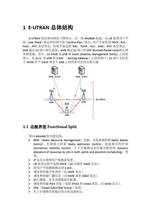
1E-UTRAN总体结构E-UTRAN的总体结构如下图所示,由一组eNoBeB组成,为UE提供用户平面(User Plane)协议和控制平面(Control Plan)协议。
用户平面包括PDCP、RLC、MAC、PHY各层协议;控制平面包括RRC、PDCP、RLC、MAC、PHY各层协议。
eNB通过X2接口相互连接;eNB通过S1接口和EPC (Evolved Packet Core)核心网络相连接,其中,S1-MME是eNB和MME (Mobility Management Entity) 之间的接口,而S1-U 是eNB和S-GW (Serving Gateway)之间的接口。
S1接口支持多个MME/多个S-GW和多个eNB之间的多对多的互联互通。
E-UTRAN1.1功能界面Functional Split基站eNodeB的功能包括:RRM(Radio Resource Manegement)功能:无线承载控制Radio Bearer Control、无线准入控制Radio Admission Control、连接移动性控制Connection Mobility Control、上下行链路动态资源分配控制Dynamicallocation of resources to UEs in both uplink and downlink (scheduling),等等。
IP包头压缩和用户数据流加密。
UE附着过程中选择MME(UE未储存MME信息)。
将用户平面数据路由到S-GW。
调度和传输寻呼消息(由MME发出)。
调度和传输广播信息(由MME或者O&M发出)。
执行测量,并负责测量报告配置。
调度和传输PWS消息(包括ETWS和CMAS消息,由MME发出)。
CSG(Closed Subscriber Group)处理。
在上行链路为传输层的分组包做标记。
在没有UE移动性的情况下对S-GW重定位。
蜂窝系统切换技术论文中英文资料对照外文翻译文献

蜂窝系统切换技术论文中英文资料对照外文翻译文献一、英文原文:Handoff in Cellular SystemsNishith D. Tripathi, NortelJeffrey H. Reed and Hugh F. VanLandinghamMPRG, Virginia TechCellular SystemDeployment ScenariosThe radio propagation environment and related handoff challenges are different in different cellular structures. A handoff algorithm with fixed parameters cannot perform well in different system environments. Specific characteristics of the communication systems should be taken into account while designing handoff algorithms. Several basic cellular structures (e.g., macrocells, microcells, and overlay systems) and special architectures (e.g., underlays, multichannel bandwidth systems,and evolutionary architectures) are described next. Integrated cordless and cellular systems, integrated cellular systems, and integrated terrestrial and satellite systems are also described.MacrocellsMacrocell radii are in several kilometers. Due to the low cellcrossing rate, centralized handoff is possible despite the large number of MSs the MSC has to manage. The signal quality in the uplink and downlink is approximately the same. The transition region between the BSs is large; handoff schemes should allow some delay to avoid flip-flopping. However, the delay should beshort enough to preserve the signal quality because the interference increases as the MS penetrates the new cell. This cell penetration is called cell dragging. Macrocells have relatively gentle path loss characteristics . The averaging interval (i.e., the time period used to average the signal strength variations) should be long enough to get rid of fadingfluctuations. First- and second-generation cellular systems provide wide-area coverage even in cities using macrocells .Typically, a BS transceiver in a macrocell transmits high output power with the antenna mounted several meters high on a tower to illuminate a large area.MicrocellsSome capacity improvement techniques (e.g., larger bandwidths, improved methods for speech coding, channel coding,and modulation) will not be sufficient to satisfy the required service demand. The use of microcells is considered the single most effective means of increasing the capacity of cellular systems.Microcells increase capacity, but radio resource management becomes more difficult. Microcells can be classified as one-, two-, or threedimensional,depending on whether they are along a road or a highway, covering an area such as a number of adjacent roads,or located in multilevel buildings, respectively . Microcells can be classified as hot spots (service areas with a higher traffic density or areas that are covered poorly), downtown clustered microcells (contiguous areas serving pedestrians and mobiles), and in-building 3-D cells (serving office buildings and pedestrians).Typically, a BS transceiver in a microcell transmits low output power with the antenna mounted at lamppost level (approximately 5 m above ground).The MS also transmits low power, which leads to longer battery life. Since BS antennas have lower heights compared to the surrounding buildings, RF signals propagate mostly along the streets.The antenna may cover 100–200 m in each street direction, serving a few city blocks. This propagation environment has low time dispersion, which allows high data rates.Microcells are more sensitive to the traffic and interference than macrocells due to short-term variations (e.g., traffic and interferencevariations),medium/long-term alterations (e.g., new buildings), and incremental growth of the radio network (e.g., new BSs) . The number of handoffs per cell is increased by an order of magnitude, and the time available to make a handoff is decreased. Using an umbrella cell is one way to reduce the handoff rate. Due to the increase in the microcell boundary crossings and expected high trafficloads, a higher degree of decentralization of the handoff process becomes necessary.Microcells encounter a propagation phenomenon called the corner effect. The corner effect is characterized by a sudden large drop (e.g., 20–30 dB) in signal strength (e.g., at 10–20 m distance) when a mobile turns around a corner.The corner effect is due to the loss of the line of sight (LOS) component from the serving BS to the MS. The corner effect demands a faster handoff and can change the signal quality very fast. The corner effect is hard to predict. A long measurement averaging interval is not desirable due to the corner effect. Moving obstacles can temporarily hinder the path between a BS and an MS,which resembles the corner effect. Reference studies the properties of symmetrical cell plans in a Manhattan-type environment. Cell plans affect signal-to-interference ratio (SIR) performance in the uplink and downlink significantly. Symmetrical cell plans have four nearest co-channel BSs located at the same distance. Such cell plans can be classified into half-square (HS), full-square (FS), and rectangular (R) cell plans. These cell plans are described next.Half-Square Cell Plan—This cell planplaces BSs with omnidirectional antennas at each intersection, and each BS covers half a block in all four directions. This cell plan avoids the street corner effect and provides the highest capacity. This cell plan has only LOS handoffs. Figure 2 shows an example of a half-square cell plan in a microcellular system.Full-Square Cell Plan —There is a BSwith an omnidirectional antenna located at every other intersection, and each BS coversa block in all four directions. It is possible for an MS to experience the street corner effect for this cell plan. The FS cell plan can have LOS or NLOS handoffs. Figure 3 shows an example of a fullsquare cell plan in a microcellular system.Rectangular Cell Plan —Each BS covers a fraction of either a horizontal or vertical street with the BS located in the middle of the cell. This cell plan can easily be adapted to market penetration. Fewer BSs with high transmit power can be used initially. As user density increases, new BSs can be added with reduced transmit power from appropriate BSs.The street corner effect is possible for this cell plan. The R cell plan can have LOS or NLOS handoffs. Figure 4 shows an example of a rectangular cell plan in a microcellular system. Macrocell/Microcell Overlays Congestion of certain microcells, the lack of service of microcells in some areas, and high speed of some users are some reasons for higher handoff rates and signaling load for microcells. To alleviate some of these problems, a mixed-cell architecture (called an overlay/underlay system) consisting of largesizemacrocells (called umbrella cells or overlay cells) and small-size microcells(called underlay cells) can be used. Figure 5 illustrates an overlay system.The macrocell/microcell overlay architecture provides a balance between maximizing the number of users per unit area and minimizing the network control load associated with handoff. Macrocells provide wide-area coverage beyond microcell service areas and ensure better intercell handoff.Microcells provide capacity due to greater frequency reuse and cover areas with high traffic density (called hot spots). Examples of hot spots include an airport,a railway station, or a parking lot. In less congested areas (e.g., areas beyond a city center or outside the main streets of a city) traffic demand is not very high, and macrocells can provide adequate coverage in such areas. Macrocells also serve highspeed MSs and the areas not covered by microcells (e.g., dueto lack of channels or the MS being out of the microcell range). Also, after the microcellular system is used to its fullest extent, the overflow traffic can be routed to macrocells.One of the important issues for the overlay/underlay system is the determination of optimum distribution of channels in the macrocells and microcells.Reference evaluates four approaches to sharing the available spectrum between the two tiers. Approach 1 uses TDMA for microcell and CDMA for macrocell. Approach 2 uses CDMA for microcell and TDMA for macrocell. Approach 3 uses TDMA in both tiers, while approach 4 uses orthogonal frequency channels in both tiers.The overlay/underlay system has several advantages over a pure microcell system:• The BSs are required only in high traffic load areas. Since it is not necessary to cover the whole service area with microcells,infrastructure costs are saved.• The number of ha ndoffs in an overlay system is much less than in a microcell system because fast-moving vehicles can be connected to the overlay macrocell.• Both calling from an MS and location registration can easily be done through the microcell system.There are several classes of umbrella cells. In one class, orthogonal channels are distributed between microcells and macrocells.In another class, microcells use channels that are temporarily unused by macrocells. In yet another class,microcells reuse the channels already assigned to macrocells and use slightly higher transmit power levels to counteract the interference from the macrocells.Within the overlay/underlay system environment, four types of handovers need to be managed[19]: microcell to microcell, microcell to macrocell, macrocell to macrocell, and macrocell to microcell.Reference describes combined cell splitting and overlaying. Reuse of channels in the two cells is done by establishing an overlaid small cell served by the same cell site as the large cell. Small cells reuse the split cell’s channels because of the large distance between the split cell and the small inner cell, while the large cell cannot reuse these channels. Overlaid cells are approximately 50 percent more spectrally efficient than segmenting (the process of distributing the channels among the small- and largesize cells to avoid interference).A practical approach for implementation of a microcell system overlaid with an existing macrocell system is proposed in . This reference introduces channel segregation (a self-organized dynamic channel assignment)and automatic transmit power control to obviate the need to design channel assignment and transmit power control for the microcell system. The available channels are reused automatically between microcells and macrocells. A slight increase of transmit power for the microcell system compensates for the macrocell-to-microcell interference.Simulation results indicate that the local traffic is accommodated by the microcells laid under macrocells without any significant channel management effort. The methodology of the Global System for Mobile Communications (GSM)-based system is extended to the macrocell/microcell overlay system in. The use of random frequency hopping and adaptive frequency planning is recommended,and different issues related to handoff and frequency planning for an overlay system are discussed. Four strategies are designed to determine a suitable cell for a user for an overlay system. Two strategies are based on the dwell time (the time for which a call can be maintained in a cell without handoff), and the other two strategies are based on user speed estimation. A speed estimation technique based on dwell times is also proposed.A CDMA cellular system can provide full connectivity between the microcells and the overlaying macrocells without capacity degradation. Reference analyzes several factors that determine the cell size, the soft handoff (SHO) zone, and the capacity of the cell clusters. Several techniques for overlay-underlay cell clustering are also outlined. Application of CDMA to microcell/macrocell overlay have the following major advantages:• A heterogeneous environment can be illuminated uniformly by using a distributed antenna (with a series of radiators with different propagation delays) while still maintaining a high-quality signal.• SHO obviates the need for complex frequency planning.Reference studies the feasibility of a CDMA overlay that can share the 1850–1990 MHz personal communications services (PCS) band with existing microwave signals (transmitted by utility companies and state agencies). The results of several field tests demonstrate the application of such an overlay for the PCS band. The issue of use of a CDMA microcell underlay for an existing analog macrocell is the focus of. It is shown that high capacity can be achieved in a microcell at the expense of a slight degradation in macrocell performance.Reference finds that transmit and receive notch filters should be used at the microcell BSs. It shows that key parameters for such an overlay are the powers of the CDMA BS and MS transmitters relative to the macrocell BSs and the MSs served by the macrocells. Reference [25] studies spectrum management in an overlay system. A new cell selection method is proposed, which uses the history of microcell sojourn times. A procedure to determine an optimum velocity threshold for the proposed method is also outlined. A systematic approach to optimal frequency spectrum management is described.Special Architectures There are several special cellular architectures that try to improve spectral efficiency without a large increase in infrastructure costs. Some ofthese structures, discussed here, include an underlay/overlay system (which is different from the overlay/underlay system described earlier) and a multichannel bandwidth system. Many cellular systems are expected to evolve from a macrocellular system to an overlay/underlay system. A study that focuses on such evolution is described in [26].A Multiple-Channel-Bandwidth System—Multiple channel bandwidths can be used within a cell to improve spectral efficiency.In a multiple-channel-bandwidth system (MCBS), a cell has two or three ring-shaped regions with different bandwidth channels [28]. Figure 7 shows an MCBS. Assume that 30 kHz is the normal bandwidth for a signal.Now, for a three-ring MCBS, 30 kHz channels can be used in the outermost ring, 15 kHz channels in the middle ring, and 7.5 kHz channels in the innermost ring. The areas of these rings can be determined based on the expected traffic conditions.Thus, instead of using 30 kHz channels throughout the cell, different bandwidth channels (e.g., 15 kHz and 7.5 kHz) can be used to increase the number of channels in a cell. The MCBS uses the fact that a wide-bandwidth channel requires a lower carrier-to-interference ratio (C/I) than a narrow-bandwidth channel for the same voice quality. For example, C/I requirements for 30 kHz,15 kHz, and 7.5 kHz channel bandwidths are 18 dB, 24 dB, and 30 dB, respectively, based on subjective voice quality tests [28]. If the transmit power at a cell cite is the same for all the bandwidths, a wide channel can serve a large cell while a narrow channel can serve a relatively small cell. Moreover, since a wide channel can tolerate a higher level of co-channel interference (CCI), it can afford a smaller D/R ratio (the ratio of co-channel distance to cell radius). Thus, in the MCBS more channels become available due to multiple-bandwidth signals, and frequency can be reused more closely in a given service region due to different C/I requirements.Integrated Wireless SystemsIntegrated wireless systems are exemplified by integrated cordless and cellular systems, integrated cellular systems, and integrated terrestrial and satellite systems. Such integrated systems combine the features of individual wireless systems to achieve the goals of improved mobility and low cost.Integrated Terrestrial Systems —Terrestrial intersystem handoff may be between two cellular systems or between a cellular system and a cordless telephone system. Examples of systems that need intersystem handoffs include GSM–Digital European Cordless Telephone (DECT), CDMA in macrocells, and TDMA in microcells. When a call initiated in a cellular system controlled by an MSC enters a system controlled by another MSC, intersystem handoff is required to continue the call [29]. In this case one MSC makes a handoff request to another MSC to save the call. The MSCs need to have software for intersystem handoff if intersystem handoff is to be implemented. Compatibility between the concerned MSCs needs to be considered, too.There are several possible outcomes of an intersystem handoff [29]:• A long-distance call becomes a local call when an MS becomes a roamer.• A long-distance call becomes a local call when a roamer becomes a home mobile unit.• A local call becomes a long distance call when a home mobile unit becomes a roamer.• A local call becomes a long-distance call when a roamer becomes a home mobile unit. There is a growing trend toward service portability across dissimilar systems such as GSM and DECT [30]. For example,it is nice to have intersystem handoff between cordless and cellular coverage. Cost-effective handoff algorithms for such scenarios represent a significant research area. This article outlines different approaches to achieving intersystem handoff. Simulation results arepresented for handoff between GSM and DECT/Wide Access Communications System (WACS). The paper shows that a minor adjustment to the DECT specification can greatly simplify the implementation of an MS capable of intersystem handoff between GSM and DECT.Integrated Terrestrial and Satellite Systems—In an integrated cellular/satellite system, the advantages of satellites and cellular systems can be combined. Satellites can provide widearea coverage, completion of coverage, immediate service, and additional capacity (by handling overflow traffic). A cellular system can provide a high-capacity economical system. Some of the issues involved in an integrated system are discussed in [31]. In particular, the procedures of GSM are examined for their application to the integrated systems.The future public land mobile telecommunication system (FPLMTS) will provide a personal telephone system that enables a person with a handheld terminal to reach anywhere in the world [32]. The FPLMTS will include low Earth orbit (LEO) or geostationary Earth orbit (GEO) satellites as well as terrestrial cellular systems. When an MS is inside the coverage area of a terrestrial cellular system, the BS will act as a relay station and provide a link between the MS and the satellite.When an MS is outside the terrestrial system coverage area, it will have a direct communication link with the satellite.Different issues such as system architecture, call handling, performance analysis of the access, and transmission protocols are discussed in [32]. The two handoff scenarios in an integrated system are described below.Handoff from the Land Mobile Satellite System to the TerrestrialSystem —While operating, the MS monitors the satellite link and evaluates the link performance. The received signal strengths (RSSs) are averaged (e.g., over a 30 s time period) to minimize signal strength variations. If the RSS falls below a certain threshold N consecutive times (e.g., N = 3), the MS begins measuring RSS from the terrestrial cellular system.If the terrestrial signals are strong enough, handoff is made to the terrestrial system, provided that the terrestrial system can serve the MS.Handoff from the Terrestrial System to the Land Mobile Satellite System —When an MS is getting service from the terrestrial system, the BS sends an acknowledge request(called page) at predefined intervals to ensure that the MS is still inside the coverage area. If an acknowledge request signal from the MS (called page response) is not received at the BS for N consecutive times, it is handed off to the land mobile satellite system (LMSS).Reference [33] focuses on personalcommunication systems with hierarchical overlays that incorporate terrestrial and satellite systems. The lowest level in the hierarchy is formed by microcells. Macrocells overlay microcells and form the middle level in the hierarchy. Satellite beams overlay macrocells and constitute the topmost hierarchy level. Two types of subscribers are considered, satellite-only and dual cellular/satellite. Call attempts from satellite-only subscribers are served by satellite systems, while call attempts from dual subscribers are first directed to the serving terrestrial systems with the satellites taking care of the overflow traffic. An analytical model for teletraffic performance is developed, and performance measures such as traffic distribution, blocking probability, and forced termination probability are evaluated for low-speed and high-speed users.Handoff Evaluation MechanismsThree basic mechanisms used to evaluate the performance of handoff algorithms include the analytical, simulation, and emulation approaches. These mechanisms are described here. The Analytical Approach This approach can quickly give a preliminary idea about the performance of some handoff algorithms for simplified handoff scenarios. This approach is valid only under specified constraints (e.g., assumptions about the RSS profiles). Actual handoff procedures are quite complicated and are not memoryless.This makes the analytical approach less realistic. For real-world situations, this approach is complex and mathematically intractable. Some of the analytical approaches appearing in the literature are briefly touched on below.二、英文翻译:蜂窝系统切换技术蜂窝系统部署方案其无线电传播环境和相关切换的难度是在于针对不同的单元结构。
科技英语中英文对照翻译
mobile and cellular radio移动和细胞广播in comparison to the relative stability and modest technical developments which are occurring in long haul wideband microwave communication systems there is rapid development and expanding deployment of new mobile personal communication system. These rang from wide coverage area pagers,for simple data message transmission,which employ common standards and hence achieve contiguous coverage over large geographical areas,such as all the major urban centres and transport routes in Europe,Asia or the continental USA.This chapter discusses the special channel characteristics of mobile systems and examines the typical cellular clusters adopted to achieve continuous communication with the mobile user.It then highlights the important properties of current,and emerging,TDMA and code division multiple access(CDMA), mobile digital cellular communication systems.Private mobile radioTerrestrial mobile radio works best at around 250 MHz as lower frequencies than this suffer from noise and interference while higher frequencies experience multipath propagation from buildings,etc,section 15.2.In practice modest frequency bands are allocated between 60MHz and 2GHz. Private mobile radio(PMR) is the system which is used by taxi companies,county councils,health authorities,ambulance services,fire services,the utility industries,etc,for mobile communications.PMR has three spectral at VHF,one just below the 88 to 108 MHz FM broadcast band and one just above this band with another allocation at approximately 170MHz.There are also two allocations at UHF around 450MHz. all these spectral allocations provide a total of just over 1000 radio channels with the channels placed at 12KHz channel spacings or centre frequency offsets. Within the 12khz wide channal the analogue modulation in PMR typically allows 7khz of bandwidth for the signal transmission.when further allowance is made for the frequency drift in the oscillators of these systems a peak deviation of only 2 to 3 khz is available for the speech traffic. Traffic is normally impressed on these systems by amplitude modulation or frequency modulation and again the receiver is of the ubiquitous superheterodyne design,Figure 1.4. A double conversion receiver with two separate local oscillator stages is usually required to achieve the required gain and rejection of adjacent channel signals.One of the problems with PMR receiver is that they are requiredto detect very small signals,typically—120dBm at the antenna output,corresponding to 0.2 uV,and,after demodulating this signal,produce ann output with perhaps 1W of audio equipment, the first IF is normally at10.7MHz and the second IF is very orten at 455KHz . unfortunately,with just over 1000 available channels for the whole of the UK and between 20000and30000issued licences for these systems,it is inevitable that the average busuness user will have to share the allocated channel with other companies in their same geographical area.There are various modes of operation for mobile radio communications networks, the simplest of which is singal frequency simplex. In simplex communication, traffic is broadcast, or one way. PMR uses half duplex(see later Table 15.3) where, at the end of each transmission period, there is a handover of the single channel to the user previously receiving, in order to permit them to reply over the same channel. This is efficient in that it requires only one frequency allocation for the communication link but it has the disadvantage that all units canhear all transmissions provided they are within rage of the mobile and frequencies are allocated for the transmissions. One frequency is used for the forward or downlink, namely base-to-mobile communications. This permits simultaneous two-way communication and greatly reduces the level of interference, but it halves other’s transmissions, which can lead to contention with two mobiles attempting to initiate a call, at the same time, on the uplink in a busy syetem.Although PMR employs relatively simple techniques with analogue speech transmission there have been many enhancements to these systems over the years . Data transmission is now in widespread use in PMR systems using FSK modulation. Data transmission also allows the possibility of hard copy graphics output and it gives direct access to computer services such as databases, etc. Data prembles can also be used, in a selective calling mode, when initiating a transmission to address a special receiver and thus obtain more privacy within the system.15.4.5 Trunked radio for paramilitary use集群无线电的军事使用Another related TDMA mobile radio standard is the European trunked radio(TETRA)network which has been developed as part of the public safety radio communications service(PSRCS) for use by police, utilities, customs office, etc. TETRA in fact is part of wider international collaborations for paramilitary radio use.In these portable radios there is a need for frequency hopping (FH) to give an antieavesdropping capability and encryption for security of transmission to extend military mobile radio capabilities to paramilitary use, i.e. for police, customs and excise offices, etc. these capabilities are included in the multiband interteam radio for the associated public safety communications office in the USA while Europe has adopted the TETRA standard.TETRA is essentially the digital TDMA replacement of the analogue PMR systems. The TETRA standard has spectrum allocations of 380 to 400 and 410 to 430MHz, with the lower band used for mobile transmissions and the upper band for base station use. TETRA mobile have 1 W output power and the base stations 25 W using error with the data throughput rate varying, to meet the required quality of service. TETRA can accommodate up to four users each with a basic speech or data rate of 7.2kbit/s. with coding and signaling overheads, the final transmission rate for the four-user slot is 36 kbit/s. this equipment is large and more sophisticated than a commercial cell phone, and it sells for a very much higher price becase the production runs are much small. However, its advanced capabilities are essential for achieving paramilitary communications which are secure from eavesdropping.15.5 Code division multiple accessAnalogue communication systems predominantly adopt frequency division multiple access (FDMA), where each subscriber is allocated a narrow frequency slot within the available channel. The alternative TDMA(GSM) technique allocates the entire channel bandwidth to a subscriber but constrains the subscriber but constrains the subscriber to transmit only regular short bursts of wideband signal. Both these accessing techniques are well established for long haulterrestrial, satellite and mobile communications as they offer very good utilization of the available bandwidth.15.5.1The inflexibility of these coordinated accessing techniques has resulted in the development of new systems based on the uncoordinated spread spectrum concept. In these systems the bits of slow speed data traffic from each subscriber are deliberately multiplied by a high chip rate spreading code, forcing the low rate (narrowband data signal) to fill a wide channel bandwidth.15.7.2 3G systemsThe evolution of the third generation (3G)system began when the ITU produce the initial recommendations for a new universal mobile telecommunications system(UMTS)[www.] The 3G mobile radio service provides higher data rate services ,with a maximum data rate in excess of 2Mbit/s, but the achievable bit rate is linked to mobility. Multimedia applications encompass services such as voice, audio/video, graphics, data, Internet access and e-mail. These packet and circuit switched services have to be supported by the radio interface and the network subsystem.Several radio transmission technologies(RTT) were evaluated by the ITU and adopted into the new standard, IMT-2000. the European standardization body for 3G, the ETSI Special Mobile Group, agreed on a radio access scheme for 3G UMTS universal terrestrial radio access(UTRA) as an evolution of GSM. UTRA consists of two modes : frequency division duplex(FDD) where the uplink and downlink are transmitted on different frequencies; and time division duplex(TDD) where the uplink and downlink are time multiplexed onto the same carrier frequency. The agreement assigned the unpaired bands (i.e. for UTRA TDD ). TD-CDMA is a pure CDMA based system. Both modes of UTRA have been harmonised with respect to basic system parameters such as carrier spacing, chip rate and frame length to ensure the interworking of UTRA with GSM.The 3G proposal were predominantly based wideband CDMA(WCDMA) and a mix of FDD and TDD access techniques. WCDMA is favoured for 3G in poor propagation environments with a mix of high modest speed data traffic. It is generally accepted that CDMA is the preferred accesstechnique and, with the increase in the data rate, then the spreading modulation needs to increase to wideband transmission.WCDMA is based on 3.84Mchip/s spreading codes with spreading ratio, i.e. , K values, of 4-256 giving corresponging data ratas of 960-15 kbit/s. the upper FDD uplink band I from 1920-1980 MHz is paired with a 2110-2170 MHz downlink. In addition uplink bands II & III at 1850-1910 MHz and 1710-1785 MHz are also paired, respectively, with 1930-1990 MHz and 1805-1880 MHz allocations. the system is configured on a 10 ms frame with 15 individual slots to facilitate TDD as well as FDD transmissions. TDD is more flexible as time-slots can be dynamically reassigned to uplink and downlink functions, as required for asymmetric transfer of large files or video on demand traffic. 3G WCDMA systems use an adaptive multirate speech coder with encoded rates of 4.75-12.2 kbit/s. receivers commonly use the easily integrated direct conversion design, in place of the superheterodyne design . receiver sensitivities are typically -155dBm.The 3GPP2 standard aims to achieve a wide area mobile wireless packet switched capability with CDMA2000 1×EV DO revision A (sometimes called IS-856A). Here 1×refers to the single carrier 1.25 Mchip/s system. It achieves a 3.1 Mbit/s downlink and a delay sensitive services. The 3GPP standard has gone through many release with R4 in 2001 which introduced packet data services and R6 in 2005 to further increase the available data transmission rate . R6 pioneers the use of high-speed downlink packet access and multimedia broadcast multicast services which offer reduced delays and increased uplink data rates approaching 6 Mbit/s.In parallel with the European activities extensive work on 3G mobile radio was also performed in Japan. The Japanese standardisation body also chose WCDMA, so that the Japanese and European proposals for the FDD mode were already aligned closely. Very similar concepts have also been adopted by the North American standardization body.In order to work towards a global 3G mobile radio standard, the third generation partnership project(3GPP), consisting of members of the standardization bodies in Europe, the USA, Japan, Korea and China, was formed. It has merged the already well harmonized proposals of the regional standardization bodies to work on a common 3G international mobile radio standard, still called UTRA. The 3GPP Project 2(3GPP2), on the other hand, works towards a 3G mobile radio standard based on cdmaOne/IS-95 evolution, originally called CDMA2000.比起相对稳定、适度的技术发展是发生在宽带微波通信系统,有长期快速发展和扩大部署的新的移动个人通讯系统。
211173150_5G_NR组播广播技术实现与应用

地面数字电视网络移动通信网络固定宽带网络应用层(内容分发)传输层(核心网)接入层(无线接入网)固定宽带网91覆盖等提出了高要求,现阶段5G 网络采用3.5GHz 频段部署单层网存在上行覆盖能力较弱、上行容量较低等问题,而上行受限于终端、帧结构和频段,体验远不如下行,因此需要不断提升5G 网络的上行性能,上行增强技术研究是5G 商用网络的重点关注方向之一。
超级上行的主要原理是终端在两个载波进行上行传输的时候,通过时分的方式复用低频载波和高频载波,从而可以兼具低频穿透性好、全时隙进行上行传输,以及高频大带宽的优势,进而可以更加充分的利用上行资源,提升上行覆盖和吞吐率。
2.1 基于超级上行SUL 技术基于超级上行的SUL 技术,如图2所示:终端一条上行链路固定使用2.6GHz,在2.6GHz 载波TDD 的下行时隙,使用700MHz 辅助载波的上行传输数据;到了2.6GHz 载波的上行时隙,上行发射通道使用2.6GHz 载波,上行有2条上行发送链路,实现2.6GHz 的TDD、NR 双流上行传输。
不但上行速率得以提升,还降低了下行数据反馈的时延,间接提升了下行速率。
2.2 基于超级上行的时频双聚合技术时频双聚合技术(FAST,Fusion Assisting Super TDD)是带外聚合载波技术与上行发射通道切换技术的结合。
它基于载波聚合技术,在上下行的频域和时域深度融合多个NR 载波,可同时实现上下行覆盖增强和容量提升,在不增加硬件设备、不调整现网工参等情况下即可兼顾上下行、持续提升5G 性能,显著提升用户体验。
如图3所示,使用5G 时频双聚合技术时,在距离基站近点区域,利用FDD+TDD 同时进行上下行传输,实现大带宽和低时延;在远点则把上行切换到FDD 来提升覆盖,下行则继续保持FDD+TDD 双聚合,提升业务体验速率。
通过超级上行技术对SUL 和CA 进行增强。
由于SUL 是5G 新增技术,产业链成熟度不足,并且SUL 载波和NR 载波的紧耦合,暂不支持跨站、跨小区,对商用部署带来挑战;CA 技术产业成熟度较高,支持跨站跨小区部署,并已有5G 实验网的测试案例,主流终端芯片厂商有支持计划。
华为NBIOT白皮书英文版

Table of Contents1.Emerging Market for Low Power Services and Applications 41.1IoT development & Growing Demand for LPWA 41.2NB-IoT Use Cases & Market Potential 5 2Emerging Low Power Technologies 62.1Introduction to NB-IOT (Best Solution For LPWA ) 62.2The NB-IOT deployment scenarios 72.3Low band, an excellent choice for fast deployment 83.Shaping the Business model 93.1Value Chain and Partnerships 93.2Business Potential & Revenue model 103.3Summary 10 4IOT Use case 114.1IOT Public 114.2IOT Industry 134.3IOT Appliance 154.4IOT Personal 16 5Operator Reference Cases 185.1Smart Parking 185.2Smart Metering 195.3Pet Tracking 20 6Glossary 22Executive SummaryThe LPWA market has existed for about 10 years; it’s not a new thing. The current technologies (solutions) supporting this market are fragmented and non-standardized, therefore there are shortcomings like poor reliability, poor security, high operational and maintenance costs. Furthermore, the new overlay network deployment is complex.NB-IOT overcomes the above defects, with all the advantages like wide area ubiquitous coverage, fast upgrade of existing network, low-power consumption guaranteeing 10 year battery life, high coupling, low cost terminal, plug and play, high reliability and high carrier-class network security, unified business platform management. Initial network investment may be quite substantial and superimposed costs are very little. NB-IOT perfectly matches LPWA market requirements, enabling operators to enter this new field.NB-IOT enables operators to operate traditional businesses such as Smart Metering, Tracking, by virtue of ultra-low-cost ($ 5 ) modules and super connectivity (50K / Cell), also opens up more industry opportunities, for example, Smart City, eHealth.NB-IOT makes it possible for more things to be connected, but also managing the commercial value of the resulting Big Data is a big task, operators can carry out cooperation with related industries, in addition to selling connections, they can also sell data.1.Emerging Market for Low Power Services and Applications1.1IoT development & Growing Demand for LPWAThe Internet of Things – IoT – has moved from fiction to reality. By 2020, there will be over 14 billion network-enabled devices, according to the International Energy Agency. This compares to approximately 3.2 billion people using the internet. IoT dramatically widens the internet’s scope from people-operated computers towards autonomous smart devices. Often, these devices are connected to the internet for remote diagnostics & control, leading to cost savings. In addition, innovative IoT hardware & services can generate new revenues – for example, connected glasses used for industrial applications, more efficient logistics serving new market segments, or industrial appliances sold in a per-usage business model. In many cases, business users & private users can control their IoT application through existing smartphones and tablets, through mobile applications that interact with web servers which the connected objects connect to.Many mobile operators have set up dedicated IoT/M2M business units in order to serve the growing number of companies looking to embrace the business benefits that mobile IoT brings. Larger operators have even made acquisitions so that they can serve a wider part of the value chain and capture revenues beyond pure connectivity. As the market grows, it is becoming obvious that there are many mobile IoT use cases for which existing cellular networks are not suitable.The reasons are simple: Coverage, battery life and device cost. First, coverage: Existing cellular networks already offer very good area coverage in mature markets. However, many potential “connected objects” are located in vast remote areas, far away from the next cellular base station. If there is coverage, it is often weak which requires the device transmitter to operate at high power, draining the battery. In addition, cellular networks are not optimized for applications that occasionally transmit small amounts of data. A battery life of several years combined with an inexpensive device cannot be realized on existing cellular standards, as they do not support the required power saving mechanisms.The third aspect is device cost: Mobile devices working on GSM, 3G and LTE are designed for a variety of services, including mobile voice, messaging and high-speed data transmission. However, NB-IoT applications do not utilize any of this; they just require low-speed but reliable data transfer, and an appropriate level of reliability. Therefore, using cellular devices for NB-IoT applications means using devices that are too expensive for the application. Many of the NB-IoT use cases require a low device price, not just in order to have a positive business case for the service operation, but also due to practical aspects such as ease of installation or risk of theft.In summary, there are strong market trends pointing at growing demand for NB-IoT applications, while the networks that can efficiently serve such applications are not in place yet. This whitepaper examines trends in the market for NB-IoT applications and discusses technology options that operators can choose from in order to enter this new business.1.2 NB-IoT Use Cases & Market PotentialThe strong growth in the NB-IoT market has motivated many analyst firms to create forecasts showing the expected numbers of connections as well as the revenue potential. Generally, the global IoT market is expected to be worth trillions of dollars by 2020. The NB-IoT market is a subset of this, and it is important for operators to understand the revenue potential in the countries they operate in. Before looking into specific countries, we need to identify the industries or verticals where NB-IoT can add value. Figure 1 below shows nine industries where we see major market potential for NB-IoT services:Figure 1: Target Industries for NB-IoT Services Huawei’s business case analytics is designed to evaluate the NB -IoT business for specificindustries, countries or regions. Based on our deep country-specific research which includes social and demographic data evaluation, we have modeled how the adoption rates for different NB-IoT applications will develop during the next five years.Our forecasts are based on use cases; distinct NB-IoT applications that will often be deployed in more than one industry. The model currently includes over fifty use cases, covering many service categories such as:∙Smart metering (electricity, gas and water) ∙Facility management services ∙Intruder alarms & fire alarms for homes & commercial properties ∙Connected personal appliances measuring health parameters ∙ Tracking of persons, animals or objectsAgriculture Health Care /E-Health Retail Safety and SecurityAutomotive &LogisticsEnergy &Utilities Manufacturing Smart City Smart Home∙ Smart city infrastructure such as street lamps or dustbins∙ Connected industrial appliances such as welding machines or air compressors.Figure 2 below shows as one output example of five-year revenue forecast (connectivity only) by Huawei for Germany divided by nine industries: Figure 2: Five-year NB-IoT revenue forecast for GermanyThe overall sum of 1.67 billion USD for five years equals a per-year NB-IoT revenue of 334 million USD. This would equal to a revenue uplift of 2.2% for the existing German operators thanks to the launch of NB-IoT services. This show, just as starting point, that already with conservativeassumptions, NB-IoT is a promising new business area which operators should invest into now, if they do not want other players to capture this attractive market. 2 Emerging Low Power Technologies2.1 Introduction to NB-IOT (Best Solution For LPWA )As mentioned earlier services that leverage low power wide area networks mainly require deep / wide coverage, low power consumption and massive connections. There are several inherent characteristics of the NB-IOT technology that makes it the best for LPWA deployment.15922518011778175227276233Overall Revenues:1.67 bn USDFigure 3: Inherent capabilities of NB-IOTMoreover low power consumption is a prerequisite for almost 80% of all LPWA use cases, ranging from applications like smart meter, smart parking, and wearables to smart grid. Additionally, with the availability of massive connections it is possible to make everything around us smart.To realize this, it’s ideal to have about 50K devices per cell; this is possible assuming there are the household density per every sq m is 1500 with 40 devices in every household.When we compare inherent capabilities of NB-IOT with other LPWA technologies like e-MTC, SigFox and Lora, NB-IOT offers better performance. Furthermore, when we look at all the technologies in terms of network investment, coverage scenario, uplink and downlink traffic and network reliability we realize that NB-IOT is the most suitable technology.Additionally from a performance point of view, NB-IOT guarantees 20+dB coverage, ~1000x connections, ~10 years using only 200 KHz bandwidth whereas the other technologies like eMTC, SigFox offers far less in terms of performance.NB-IOT has quite an extensive ecosystem mainly because of its support from many global top operators. Most importantly unlicensed solutions can’t guarant ee reliability and security.2.2The NB-IOT deployment scenariosThe recently 3GPP agreed technology for LPWA deployment NB-IOT will offer three deployment scenarios; these are, Guard Band, In Band and Stand Alone.Standalone deployment is mainly utilizes new bandwidth where as guard band deployment is done using the bandwidth reserved in the guard band of the existing LTE network, In Band on the other hand makes use of the same resource block in the LTE carrier of the existing LTE network.Figure 4: Three deployment scenarios of NB-IOTIn summary, it becomes clear that the Standalone and Guard band deployment options tend to offer the best performance in terms of improved indoor coverage, FDMA (GMSK) also offers about 20% power consumption saving and lower cost.2.3Low band, an excellent choice for fast deploymentLow band is quite known for its excellent performance in terms of coverage; furthermore leveraging the inherent characteristics of this frequency band in deploying NBIOT offers several benefits. It is widely known that several operators around the globe use the 900MHz frequency band for GSM voice deployments because of its extensive coverage capability. This is possible because such low frequency bands have excellent propagation characteristics and this generally improves the indoor penetration.Deploying NB-IOT in frequency bands like 700MHz, 800MHz, and 900MHz is a great choice because they provide an already large and established ecosystem since quite a number of operators select them; it also offers benefits in terms of site number. There is quite a substantial number of commercial networks both UMTS and LTE that are currently running on the 900MHz frequency band. Analyst firms recently confirmed that there are about 14 LTE 900MHz commercial networks as at July 2015.A few examples of such operators can be found in the Czech Republic and Sweden. There are other operators in South Korea with commercial LTE networks on the 800MHz frequency band. For mobile operators who are already running GSM 900MHz, it is possible to just upgrade, some operators might also be running on LTE 800MHz, there is a clear upgrade pathway to NB-IOT for such operators too.3.Shaping the Business model3.1Value Chain and PartnershipsAs shown in the NB-IoT business study for Germany, already connectivity is a valuable contributor to the operator’s bottom line. Partnerships with IoT technology providers and alliances with chipset manufacturers are helping the operators to secure this part of the value chain as we see it today for some of the NB-IoT solutions, e.g. smart metering, smart parking and pet tracking. At the moment we see connectivity platforms already in the cloud in many markets where operators have deployed IoT services.But there is more in than just connectivity. Operators have a chance to go further up the value chain by taken over more responsibilities than pure connectivity.Figure 5 : Telco business models for NB-IoT along the value chain Consequently the next step towards an integrated offer would be the incorporation of more functionality which points towards a setup, where the operators can offer the full NB –IoT Network as a service in the cloud to end to end service providers which are either private or governmental entities, according to the addressed industries or verticals .This will create for the operator the opportunity to lever its asset as security, billing and big data into that domain. Quality of service assurance and service level agreements are common in the telco space and could be leveraged into the NB-IoT Network as a service business model Following this idea even more, operators themselves can enter the IoT business as an end to end service provider by adding customer management and system integration functionalities on top. The operator as e2e business owner can also outsource certain parts of the e2e domain to its partners, sharing effort and revenues, and to expand the operators own experience in the OTT domain. However competing in the OTT domain is not comm on to most of the today’s opera tors and could be quite challenging.3.2 Business Potential & Revenue modelThe business is scalable and can be grown by demands by orienting the service introduction and go to market strategy on use cases which are profitable at a given point of time and contributing to the operator’s bottom line allowing further business expansion. As the operator can reuse his exi sting sites, no specific investment in towers or acquisition of sites are needed.Figure 6 : NB-IoT “time to market” and number of primary use casesThe selection of use cases can be different per operator, country and region or per addressed market. Huawei’s business modeling framework is able to address those challenges and advise on the right mix of investment, use case deployment and business model selection.3.3 SummaryThe opportunities for operators to enter business in NB-IoT domain are reflecting the huge potential of NB-IoT. Operators can choose from three basic setups according to their strategy per country or region:Connectivity: For the Internet of Things a reliable connectivity is required, but there are more business opportunities as just to engage in connectivityNB-IoT networks can be deployed by usingthe existing sites 1 Year 3 Year5 YearSmart ElectricitySmart WaterMeteringAlarms in Single-Family Houses Motor VehicleTrackingConnected StreetLamp………..Connected BloodPressure Meter Smart GasNB- IoT NW as a Service: Carrier grade solutions with security, billing, big data integration and QoS assurance allow the creation of new businesses and improvements to existing ones on a solid technological basis. NB-IoT Network as a service is supporting the global trends of network virtualization and cloud based service provision.End to End service provision: Operators may choose to extend into the e2e service provider domain for specific IoT solutions, but this needs careful planning, technology and business partnerships with players in the industry, including outsourcing and revenue sharing models.4IOT Use CaseIn this section, the various services and applications supported by LPWA has been classified under four categories; IOT Appliance, Personal, Public and Industry.Figure 7: Four use case categories for NB-IOT4.1IOT PublicAs the name suggests, IOT public focuses on LPWA applications that serves the general public; below are a few examples.i.Smart meteringSmart metering helps saves manpower by remotely collecting electricity, water and gas meter data over the cellular network. This is gaining quite an amount of momentum with most of the top European MNOs taking an interest in this topic mainly due to the market opportunity it presents. Smart metering will consequently help cut down cost generated from manual meter reading andchanging of meter batteries, which seems to be the two major cost drivers for conventional metering. Smart metering includes smart meters for water, gas and electricity.Figure 8: Smart metering use caseii.Alarms & Event DetectorsSecurity has always been a very important aspect of human living , people at all times want to be guaranteed of home safety. Alarms and event detection will help to rapidly inform that user about a detected home intrusion. This system will not only offer inteligent protection from intrusion but will also offer intelligence for detected events that can lead to a fire outbreak like a sudden increase in home temperature or smoke. Alarms and events detectors will make use of sensors placed devices in ideal locations in the home that constantly communicates with the LPWA network, this use case will make use of a very low data throughput and battery life of the devices will be ultra critical.Figure 9: Alarm & Event Detectorsiii. Smart garbage binsGarbage bins in city are not built by demand, and most of time the collecting trucks routes and schedule are fixed which is not optimal for a smooth collection. Smart garbage cans can signal to the waste management agent when the garbage can is full and in need of service, the best collection route will be calculated and delivered to the drivers. Historical collection data can provide optimized routes and guide on the right-size garbage can for each location. Charging for this service can be done on sensor amount or on monthly fee basis.Figure 10: Smart garbage bin4.2IOT INDUSTRYIOT Industry mainly delivers low power wide area applications that help to improve general enterprise and industrial efficiency; here are a few examples;iv.Logistics trackingLarge volumes of sensor data sent from tracking devices on shipping containers are aggregated and taken into an analysis to ensure that real time tracking of the location of shipments can be made possible. Alerts and optimized service recommendations are sent to technicians on their iPads, so that they can take preemptive actions in -real time. Charging model for this application can be done on a monthly payment or postpaid basis.Figure 11: Logistics tracking use casev. Asset trackingAsset tracking mainly deals with monitoring methods of physical assets made possible by a module on the asset broadcasting its location. Assets are usually tracked using GPS technology. This service is best leveraged in the logistics and transportation management industry, where through the use of sensors in modules sending information over the cellular network it is possible to gather and manage data relating to the current geographical location of assets. Asset tracking helps the owners of the assets to detect and preemtively react to unexpected events.Figure 12: Asset tracking use casevi. Smart agriculture NB-IOTTracking ApplicationSatelliteFarming industry is a sector with slim margins, and the way to survive in this industry is to optimize the general agriculture production including crops and livestock.Developing a sensor function to ensure the feeding of cattle has an optimized mix of nutritions to improve the yields from farming, and to reduce the waste of cattle feed. Installing sensors in the farming equipment that mix the cattle’s feed, through sensors measurements the variation in the cattle diet can quickly be identified, assessed and corrected. Charging model for this application can be done on a monthly payment or postpaid basis.Figure 13: Smart agriculture4.3IOT ApplianceConventionally, smart home application are deployed on short range technologies like Z-Wave, Zigbee but a home gateway is needed. In the case, where the appliance is embedded with an NB-IOT chipset the benefits are surprising. For example, management becomes more efficient through improvements in big data analysis. IOT appliance mainly comprises of LPWA applications that aims to provide intelligence for the user through sensors and devices that are found in the local area. Below are a few examples;Figure 14: IOT Appliance use cases4.4IOT PersonalIOT personal largely features LPWA applications that create a personal area network for the purposes of information exchange for the user. Below are a few examples;vii.WearablesConnected wearables in the past few years have taken center stage and increasingly becoming a lucrative industry as it is an application that mainly revolves around health, fitness and wellness. According to Cisco, there will be 177M connected wearables by 2018. Its market value is estimated at $250M in 2015 and is set to rise to $1.6B in 2022. A report released by Research&Markets and Berg Insight also estimated that global shipments of connected wearables in 2014 was 19 million and this figure is set to hit 168.2million by 2019 growing at a CAGR of 74.8%. Some of the few products that are making inroads in this industry are JawBone, GoPro & Nike just to name a few. While smartphone giants like Apple, Sony and Samsung are more linked to smartwatches.Figure 15: Wearables use caseviii. Smart bicycleFor bike rental companies it is vital to keep track of where the bike is at the moment, especially if it gets stolen. A bike rental company in Holland has embedded an M2M SIM card into the bike’s frame, and in this way the bike rental company can always find the bike. The M2M SIM is embedded into the bike in a non visible placeIf the bike is not returned to the rental company then the bike is positioned via the SIM. The rental cost for bikes can be reduced since the number of stolen bikes dramatically decrease. Stolen bikes can easily and quickly be located by the police via the SIM. Charging model can be done on a monthly payment or postpaid basis.Figure 16: Smart bicyclei.Kids monitoring use caseThe world’s population is aging, and senior people living alone at home need care in an easy and affordable way. Also parents have a great interest in being assured about their wellbeing andactivities. This use case provides realtime tracking of kids and the elderly. The information about their activities to the cloud. Real-time insights about the their status can be received on the users smartphone or other device.Figure 17: Kids monitoring use case5Operator Reference Cases5.1Smart ParkingParking can be a challenging issue, especially in urban areas where 30 % of all traffic congestion is caused by drivers circling around to find a parking space. Smart parking provides parking information to citizens in real time to enable better parking management. Huawei and a top operator are working on a smart parking project. Operator expects tens of millions of devices to be connected with this smart parking service. Another collaborator in this project is Neul, who provides the platform.Figure 18: Smart Parking reference caseIn this service, sensors that are placed under cars will communicate with the parking server through the cellular network to gain parking information. The operator and Huawei completed field trials for the smart parking project in July 2015 with Proof of Concepts already done. The commercialization of this project is expected in the second quarter of 2016.5.2Smart MeteringSmart metering as mentioned earlier enable the automated collection of utility meter data (Electricity, Water & Gas). Huawei and another operator are collaborating on an end to end smart metering solution. During Mobile World Congress 2015, Huawei and the operator unveiled this partnership on end to end smart metering project. Other players like Neul, Veolia, Kamstrup and Ublox are all collaborating efforts on this project that is planned to be launched in the first half of 2016.Figure 19: Smart metering reference caseProof of Concept for the smart metering project have already been completed, Huawei and the operator are looking forward to conducting field trials in November mercialization of the smart metering project is expected in the third quarter of 2016.5.3Pet TrackingHumans and their pets share a good bond, unfortunately many users often face issues regarding lost or stolen pets. Pet tracking use case is one application that helps the user to keep track of its pets activities and most importantly location at all times. A small lightweight device placed around the neck of the pet embedded with an NB-IOT chipset helps to send tracking information to its user’s device. This NB-IOT devices collects and sends location information leveraging GPS and Location Based Services and this can be done either periodically or in real time based on the users’ preferences.Figure 20: Pet tracking reference caseThe user can then receive the information with a tracking route that is already integrated with the map. Furthermore, this device is embedded with several forms of alarms that can alert the user when the device battery is running low .Huawei is collaborating with other industry players and another operator on the pet tracking application.6GlossaryNBIOT- Narrow Band Internet of ThingsPSD – Power Spectral DensityLPWA-Low Power Wide AreaGMSK – Gaussian Minimum Shift KeyingCAGR – Compound Annual Growth RateSC FDMA – Single Carrier Frequency Division Multiple Access DL – DownlinkUL – UplinkeHealth – Electronic Health3GPP – Third Generation Partnership ProjectTTM – Time to MarketdB – DecibelGPRS – General Packet Radio ServiceMNO – Mobile Network OperatorPoC – Proof of ConceptKHz – Kilohertz2017。
GSM网优考题(答案)
GSM网优考试试题*考试时间为120分钟,闭卷考试。
总分计100分。
姓名:一:填空题(30个空,每个1分,共30分)1.数字移动通信系统GSM中,A接口是MSC和BSC之间的接口,接口速率为2Mbps,Abits接口是和间的接口。
手机MS和BTS之间的接口是。
2. PCM30/32路系统中,编码过程:,,。
每个话路的数据速率是。
3. 光纤按传输总模数可分为和。
4. GSM系统的三要素为:、、。
5.为了减少快衰落的影响,GSM采用技术实现时间分集,技术实现频率分集,主、技术实现空间分集。
6.对于GSM系统,帧跳频的跳频频率是Hz7.多普勒效应引起的附加频移称为多普勒频移,若移动台远离基站移动,则此时因多普勒频移会造成接收频率偏8.在GSM系统中,功率控制是按级(2dB /每级)调整的,900M手机的发射最大功率是2W,对应的33 dBm,根据测量报告要求手机降4级发射,其对应的发射功率是9.在GSM系统中,900M频段的11号频点对应的上行中心频率是 892.2 MHz , 下行中心频率是 937.2 MHz 。
上行下行频率的双工间隔是 45 MHz 。
10. GSM 系统载频带宽为__HZ,一个载频可带有______个物理信道,其调制技术采用_____。
11. 在路测工具的系统设置中,应注意是否下行使用了DTX功能,当下行使用DTX功能时应将图形显示设置的DTX状态选择为方式。
12. 在GSM系统中,指配流程分成三类:、。
二:判断题(10个,每个1分,共10分)1.增益是天线的重要指标之一,天线通过天线振子的组合并改变其馈电方式从而使总的辐射信号的能量得到增加。
()2.定向天线的前后比是指主瓣的最大辐射方向的功率通量密度与相反方向附近的最大功率通量密度之比值。
()3.位置更新分为:正常位置更新、周期性位置更新、IMSI附着位置更新。
()4.移动主叫(始呼)包括MS拨打MS、MS拨打固定电话、短消息始发。
锐捷 RG-ES200 系列交换机 Web 配置指南说明书
Ruijie RG-ES200 Series Switches Web-Based Configuration GuideCopyright StatementRuijie Networks©2020Ruijie Networks reserves all copyrights of this document. Any reproduction, excerption, backup, modification, transmission, translation or commercial use of this document or any portion of this document, in any form or by any means, without the prior written consent of Ruijie Networks is prohibited.Exemption StatementThis document is provided “as is”. The contents of this document are subject to c hange without any notice. Please obtain the latest information through the Ruijie Networks website. Ruijie Networks endeavors to ensure content accuracy and will not shoulder any responsibility for losses and damages caused due to content omissions, inaccuracies or errors.PrefaceThank you for using our products.AudienceThis manual is intended for:●Network engineers●Technical support and servicing engineers●Network administratorsObtaining TechnicalAssistance●Ruijie Networks Website: https:///●Technical Support Website: https:///support ●Case Portal: https://●Community: https://●Technical Support Email: *****************************●Skype: *****************************Related DocumentsConventionsThis manual uses the following conventions:Configuration Guide Overview 1 OvervieweWeb is a Web-based management system that manages or configures devices. You can access eWeb via browsers such as Google Chrome.Web-based management involves the Web server and Web client. The Web server is integrated in a device, and is used to receive and process requests from the client, and return processing results to the client. The Web client usually refers to a browser, such as Google Chrome, IE, or Firefox.1.1 ConventionsIn this document:●Texts in bold are names of buttons (for example, Save) or other graphical user interface (GUI) elements (for example,VLAN).●Devices of different models have slightly different functions. This document uses RG-ES218GC-P as an example fordescription.Only RG-ES226GC-P, RG-ES218GC-P, RG-ES209GC-P, RG-ES209C-P, RG-ES205GC-P, and RG-ES205C-P support the PoE function and configuration.Only RG-ES226GC-P, RG-ES218GC-P, RG-ES224GC, and RG-ES216GC support the multi-DHCP alarm function.The device initially adopts an English OS by default. After it is accessed, the device language can be set to the language used by the current browser. A manually set device language has a higher priority than the language of the browser.The cloud status and online upgrade are not supported in the English OS.2 Configuration Guide2.1 PreparationsScenarioAs shown in the figure below, administrators can access the device from a browser and configure the device through the eWeb management system.Deliver or request commands through AJAX.Administrator Return dataWebserviceDeviceDeployment↘Configuration Environment RequirementsClient requirements:●An administrator can log into the eWeb management system from a Web browser to manage the device. The clientrefers to a PC or some other mobile endpoints such as laptops or tablets.●Google Chrome, Firefox, IE9.0 and later versions, and some Chromium-based browsers (such as 360 ExtremeExplorer) are supported. Exceptions such as garble or format error may occur if an unsupported browser is used.●1024 x 768 or a higher resolution is recommended. If other resolutions are used, the page fonts and formats may not bealigned, the GUI is less artistic, or other exceptions may occur.●Ensure that the client IP address is set to be in the same network segment as the device management address. Thenyou can open the browser and enter the device management address to configure the device. When you use the reserved management address 10.44.77.200 of the device, ensure that the client is directly connected to the switch. To log into the eWeb management system, open Google Chrome, enter 10.44.77.200 in the address bar, and press Enter, as shown in the figure below.The device homepage appears by default. In addition, a dialog box is displayed, asking you whether to change the default password. (The factory settings of the device can be modified only after the password is changed as prompted.)2.2 Default Password ConfigurationUnder factory default settings, the eWeb management system displays a prompt, asking you whether to change the password. (You can configure switch functions only after changing the password.)Click OK. The Web management system automatically redirects to the Account Settings page (or you can choose SystemSettings > Account Settings to configure the login password).Enter a new password according to password rules and then click Save. In the displayed dialog box, click OK.2.3 Introduction to the Web GUIThe figure below shows the Web GUI of RG-ES226GC-P.The Web GUI consists of the left and right portions.The left portion is the menu bar and provides links to all configuration functions of the device, such as Monitoring and VLAN Settings .The right portion is the content area, which is divided into two parts. The upper part displays the port status bar and the Logout button while the lower part displays the content and configuration area. Port status bar:Move the cursor over a port. Basic information about the port (including the port connection status, speed, duplex mode, and flow control status) is displayed. There are uplink and downlink ports. You can click Collapse to hide the port status bar so that a larger content area is displayed for viewing configuration details.Functionmenu barSwitch port status barSystem information barPort details list and basic function configuration barWhen a port is down, the port icon is grayed out. When a loop occurs on a port, the port icon is displayed inyellow . When a port works properly, the port icon is displayed in green .Description of the content area:Texts in orange indicate a description of a function. Texts in red indicate notes of a function. A question mark (?) against an orange background indicates an operation prompt, and the prompt pops up when the cursor ismoved over thequestion mark.3 eWeb Configuration3.1 HomepageThe homepage displays basic information about the device, interface status, and VLAN Settings .Move the cursor over thequestion mark to pop up adescription of the operation.The following figure shows a multi-DHCP alarm displayed on the homepage.Move the cursor over the icon. Alarm information (VLAN, port, IP address, and MAC address) is displayed.3.2 System Settings3.2.1 Device InfoDetails about the device are displayed.Function linkChange thedevice name.PortconfigurationareaDownlink device search3.2.2 IP SettingsConfigure the management IP address and management VLAN for the device. Auto Obtain IP is set to Enabled by default. When VLAN Settings is set to off, the management VLAN is 1.When VLAN Settings is set to on, the following figure is displayed.When VLAN Settings is set to on, select the management VLAN from configured VLANs (you can choose VLAN Settings > VLAN Members to add a VLAN).The device will be disconnected for a short time during IP address configuration. If Auto Obtain IP is set to Enabled, the device needs to obtain an IP address from the uplink device, or you can enter the management IP address(10.44.77.200) for Web management.After VLAN Settings is set to on, change the management VLAN and check whether the port VLAN contains the management VLAN to avoid inaccessible IP address.3.2.3 Account SettingsThe settings are the same as those in 2.2 Default Password Configuration.When switches are managed via an ad hoc network, no management password can be separately configured for the device and the global password needs to be configured on the master device.3.2.4 RebootClick Reboot to reboot the switch.3.2.5 Upgrade3.2.5.1 Local UpgradeClick Select File. In the displayed dialog box, select a target upgrade package. (The software upgrade package is an xxx.bin file while the system upgrade package is an xxxx.tar.gz file. You need to manually decompress the package and select the xxx.bin file for upgrade.)Keep Old Config is selected by default. If the target version is much later than the current version, it is recommended to uncheck Keep Old Config.3.2.5.2 Online UpgradeOnline upgrade will keep your current configuration. If there is a new version available, the Upgrade button can be clicked. Click the Upgrade button and then confirm upgrade. The device will download the new version from the cloud and upgrade to the target version. The time it takes depends on network performance.3.2.6 Restore DefaultClick Restore to restore factory settings and reboot the device.3.3 Monitoring3.3.1 SwitchesWhen switches are managed by a master device (some functions such as account management are unavailable), the master device of the ad hoc network is displayed. You can access the master device to configure the ad hoc network.The device can discover and display switches in the same management VLAN. The number of discovered switches in a management VLAN varies with the switch model:The following models can discover up to 32 switches in the management VLAN: RG-ES226GC-P, RG-ES218GC-P, RG-ES224GC, and RG-ES216GC.The following models can discover up to 16 switches in the management VLAN: RG-ES205C-P, RG-ES205GC-P, RG-ES209C-P, and RG-ES209GC-P.The first entry shows information about the current device and other entries show information about the discovered devices. You can click an IP address to redirect to the eWeb management of a specific device (login is required).3.3.2 Port StatisticsThe Port Statistics page displays the statistics and status of device ports, such as port Rx/Tx rate and Rx/Tx packets.3.3.3 Cable DiagnosticsYou can learn the general cable status of ports through cable diagnostics, for example, whether a cable is short-circuited or disconnected.Click Start. Test results will be displayed.3.3.4 Loop GuardAfter loop guard is enabled (which is disabled by default), a port causing a loop on the current device will be automatically disabled. After the loop is removed, the port is restored automatically.3.4 Switch Settings3.4.1 Port SettingsOn the Port Settings page, you can configure the port status, speed, duplex mode, and flow control attribute in batches. The page is divided into two parts:Configuration part:Select a port, configure attributes for the port, and then click Save to deliver the configuration to the port.Display part:Configured attributes and actual attributes of each port are displayed.A disabled port cannot transmit or receive packets (the PoE function is not affected). Disabling all ports of a switch willmake the switch unmanageable. Therefore, exercise caution when disabling ports.3.4.2 Port MirroringPort mirroring forwards input/output packets of one or more source port to the destination port to monitor the network.packets. They cannot transmit data to the switch.3.4.3 Port IsolationPort isolation implements layer-2 isolation of packets. After port isolation is enabled (which is disabled by default), data can be forwarded only between uplink ports and downlink ports, and downlink ports cannot forward packets to each other.3.4.4 Static MACThe Static MAC Address page is divided into two parts:Adding a static MAC address:Enter a valid MAC address and VLAN ID, select a port, and then click Add to add a static MAC address.Displaying and deleting a static MAC address:After a valid static MAC address is added, its information is displayed in the list below. Select a static MAC address and click Delete to delete the static MAC address.Up to 16 static MAC addresses can be added.After VLAN Settings is set to off, no VLAN ID needs to be entered to add a static MAC address.3.4.5 Search MACWith the search MAC function, you can search for the MAC addresses learned by the device. MAC addresses can be fuzzily searched. You can enter a part of a complete MAC address (such as 00:74:9c:1e:4b:f4) for searching.After VLAN Settings is set to off, the VLAN ID column will not be displayed.3.4.6 MAC ListThe MAC Address Info page lists MAC addresses learned by the device.Click Clear Dynamic MAC. The device re-obtains the list of learned MAC addresses.After VLAN Settings is set to off, the VLAN ID column will not be displayed.3.4.7 DHCP SnoopingYou can configure the DHCP snooping function for the device.After DHCP Snooping is set to on, as shown in the figure above, the device sets the uplink port as a trusted port by default. You can select a port and click Save to set the port as a trusted port.DHCP Snooping functions as a DHCP packet filter. The DHCP request packets will be forwarded only to the trusted port.The DHCP response packets from only the trusted port will be allowed for forwarding.The port connected to the DHCP server (uplink port) is configured as the trusted port generally.3.5 VLAN SettingsYou can add or delete VLANs, and configure port VLANs (only when VLAN Settings is set to on).3.5.1 VLAN MembersWhen VLAN Settings is set to off, the page is shown in the figure below:When VLAN Settings is set to on, the page is shown in the figure below:After VLAN Settings is set to on, enter a valid VLAN ID and click Add to configure a new VLAN. In the VLAN list, you can select VLANs and click Delete to delete them in batches.Up to 16 VLANs can be configured.A VLAN ID bound to a port cannot be deleted.3.5.2 VLAN SettingsWhen VLAN Settings is set to off, the page is shown in the figure below:When VLAN Settings is set to on, the page is shown in the figure below:The VLAN Settings page is divided into two parts:The upper part enables port VLAN configuration. You can select a port, set the VLAN type (Access or Trunk; when Trunk is selected, Permit VLAN can be configured), Permit VLAN, and Native VLAN, and click Save to save the port VLAN configuration.The lower part lists the port and VLAN settings.Note: Packets from ports in the native VLAN are untagged.3.6 QoS SettingsQoS settings include the port rate and storm control function.3.6.1 Port RateYou can configure the input and output rates for a port. The Port Rate page is divided into two parts:Configuration part:Select one or more ports, set the port type and whether to enable rate limiting (if yes, enter the rate limit value of the port), and click Save.Display part:The input and output rates configured for device ports are displayed.For RG-ES205C-P, the range of the port rate limit is from 1 Mbit/s to 100 Mbit/s.For RG-ES209C-P, the maximum rate is 100 Mbit/s for ports 1–8, and the actual rate is 100 Mbit/s if a greater rate is configured. The range of the port rate limit is from 1 Mbit/s to 1000 Mbit/s for port 9.For RG-ES226GC-P, RG-ES218GC-P, RG-ES205GC-P, and RG-ES209GC-P, the range of the port rate limit is from 1 Mbit/s to 1000 Mbit/s.3.6.2 Storm ControlThe Storm Control page consists of the port storm control configuration and display.Configuration part:Specify the storm control type, select ports, enable storm control, and enter the storm control rate. Click Save to configure storm control.Display part:The storm control types and rates configured for device ports are displayed (when storm control is enabled, the storm control rates are displayed).For RG-ES205C-P, the range of the storm control rate is from 1 Mbit/s to 100 Mbit/s.For RG-ES209C-P, the maximum rate is 100 Mbit/s for ports 1–8, and the actual rate is 100 Mbit/s if a greater rate is configured. The range of the storm control rate is 1 from Mbit/s to 1000 Mbit/s for port 9.For RG-ES226GC-P, RG-ES218GC-P, RG-ES205GC-P, and RG-ES209GC-P, the range of the storm control rate is from 1 Mbit/s to 1000 Mbit/s.3.7 PoE SettingsThe PoE system status and PoE port status of the device are displayed.System status:The total power, used power, remaining power, and work status of the PoE function of the device are displayed.Port status:The PoE voltage, current, power, and current power status of ports are displayed. You can control whether to enable PoE function on a port and restart PDs.Fiber ports (last two ports) of RG-ES226GC-P and RG-ES218GC-P do not support the PoE function.Disabling PoE on a port will stop powering downlink devices connected to the port.Configuration Guide FAQs4 FAQsQ1: What can I do when I failed to log into the eWeb management system?A: Perform the following steps:(1) Check that a PC network cable is correctly connected to a device port and the port indicator blinks.(2) Before accessing the setup GUI, you are advised to configure a static IP address for the PC. Set the IP address to 10.44.77.XXX (for example, 10.44.77.199; the IP address cannot be the same as the device IP address 10.44.77.200) and subnet mask to 255.255.255.0.(3) Run the ping command to test the connectivity between the PC and the device.Q2: What can I do when I forget the device username and password? How can I restore factory settings?If you forget the login password, hold down the Reset button on the panel for 5 seconds after the device is powered on. Factory settings are restored after the device restarts.。
CE资源介绍与消耗计算专题
UMTS网规CE计算专题摘要:本文给出了CE的定义、中兴通讯CE资源消耗的特点和各业务CE计算的方法和举例,并讨论了因空口受限对基站单载波配置下CE消耗上限的影响。
关键词:UMTS CE计算单站上限空口受限1.CE的定义及中兴通讯CE资源消耗的特点CE即Channel Element,信道单元,是基带处理板中的一个逻辑单元。
基站中的基带处理板完成基带的前向调制和反向解调,实现Rake接收、软切换、功率控制等关键技术。
为了反映基带处理板硬件和软件资源的占用情况,抽象出CE这个可以反映基带资源消耗情况的管理模型。
CE定义为一个12.2K语音加一个3.4K信令消耗的资源。
为了方便计算,同时体现产品的竞争优势,公共信道、压缩模式、收发分集、更软切换等消耗的资源已经在基带板中预留了,并不体现在计算过程中,即网规口径为以上各项均不消耗CE资源。
中兴公司NodeB的CE消耗呈现以下特点:1.目前使用的基带处理板BPC板,单板可支持上下各192个CE,且上下行资源独立,估算时以上下行CE中较大者为限。
2.中兴NodeB一块基带板可同时支持HSDPA和R99,并有专门的芯片来处理HSDPA业务,基带处理版已经为HSDPA的HS-DSCH信道、HS-SCCH及HS-DPDCH信道预留了处理资源,HSDPA的引入不消耗R99的CE资源。
3.公共信道消耗的CE已经预留,无需为上下行公共信道计算CE资源。
4.压缩模式、收发分集及更软切换消耗的CE已经预留,对CE消耗没有影响。
5.HSDPA和HSUPA调度器占用的资源已经按最保守的情况预留,不占用CE资源。
2.CE的计算过程CE估算的过程如下图所示:图1 CE估算过程即分别计算R99 CS、R99 PS、HSDPA伴随信道、HSUPA业务及伴随信道消耗的CE,然后相加求和。
2.1 R99业务消耗的CE一个CE定义为一个AMR12.2k语音加上3.4k的信令,即一个语音用户消耗一个CE,那么其他业务消耗的CE是多少呢?对于R99不用的承载,每连接消耗的CE是不同的,各业务消耗的CE因子如下表所示。
Ubiquiti AF-5XHD 5 GHz 长距离无线网络设备数据手册说明书
D atasheet5 GHz Carrier Radio with LTU™ TechnologyModel: AF‑5XHDUp to 1+ Gbps Real Throughput, Up to 100 km RangeThe LTU Design TeamTen years ago, Ubiquiti® sparked a global Wireless ISP revolution with the introduction of NanoStation® — a cost-disruptive 802.11 Wi-Fi long range outdoor plug and play radio. The NanoStation broke down technical and financial barriers for WISP’s around the world, enabling nearly any operator to deploy scalable networks and grow profitable business models.As bandwidth demands and scalability challenges increased through the years, Ubiquiti responded with performance-enhancing innovations such as the airMAX® TDMA protocol, PRISM® active RF filtering,and GPS synchronization — all working to extract every ounce of potential from consumer 802.11 Wi-Fi chipsets. However, we always knew that one day growing subscriber bandwidth demands combined with an increasingly crowded unlicensed RF spectrum would expose the fundamental limitations of 802.11Wi-Fi silicon and ultimately threaten the survival of our industry.Years ago, a core group of engineers at Ubiquiti set out to make sure this day would never come. We began an ambitious plan that would span millions of man hours of development and tens of millions of dollars of investment. The result was a new technology and ASIC chipset created from the ground floor up specifically for the Wireless ISP industry — a technology we believe positions our Industry to succeed in the new challenging landscape of the future. Welcome to what we call the Long Term Ubiquiti vision, or simply LTU™.OverviewUbiquiti Networks continues to disrupt the wireless broadband market with revolutionary LTU technology that breaks through the limitations of 802.11 Wi-Fi technology. Designed for use in the 5 GHz frequency band, the new airFiber AF-5XHD is Ubiquiti's first LTU radio, offering greater channel bandwidths of up to 100 MHz, and more advanced RF components. Pair the AF-5XHD with a compatible Ubiquiti® airFiber X antennaor RocketDish™ antenna for a complete 5 GHz Point-to-Point (PtP) solution.An IP67 upgrade kit is included to provide enhanced protection from dust and water.Engineered for Performance Designed specifically for the Wireless ISP industry fromthe ground floor up, theAF‑5XHD’s custom LTU siliconand radio architecture provide breakthrough performance. Its core communications processing engine surpasses the limitations inherent to generic Wi‑Fi chips to provide low latency, long-range capability, DFS flexibility, higher constellations, and better power output, along with improved receive sensitivity.The AF-5XHD features industry-leading 21.2 bps/Hz spectral efficiency*, line-rate data packet processing for up to 1.34 Gbpsof real data throughput*, and innovative xtreme Range Technology (xRT™).* Assuming 4096QAM, available with a futurefirmware upgrade.D a t a s h e e tKey FeaturesThe AF-5XHD offers the following advanced features: • Programmable Transmit Power The radio's transmit power level can be programmed up to +29 dBm.• Programmable Duty Cycle (GPS synchronized frames) asymmetric TX and RX duty cycles. TX ratios include 25%, 33%, 50%, 66.7%, and 75%.• Configurable GPS Synchronization The AF‑5XHD offers configurable support for 2, 2.5, 4, and 5 ms frames. Timing is compatible with all other synchronous systems.1 The radio can operate 1 Support for15SoftwareThe airFiber AF‑5XHD uses Ubiquiti's airOS LTU software, which offers you a variety of advanced features.Spectral Analysis with airViewairView® allows you to identify noise signatures and plan your networks to minimize noiseinterference. airView performs the following functions:• Constantly monitors environmental noise• Collects energy data points in real-time spectral views• Helps optimize channel selection, network design, and wireless performanceairView runs in the background without disabling the wireless link, so there is no disruption to the network.In airView, there are three spectral views, each of which represents different data: waveform, waterfall, and ambient noise level.airView provides powerfulspectrum analyzer functionality, eliminating the need to rent or purchase additional equipment for conducting site surveys.UNMS AppThe AF‑5XHD supports the Ubiquiti Network Management System. UNMS ™ is a comprehensivemanagement controller featuring an easy-to-navigate graphic UI. The UNMS app provides instant access to the airOS configuration interface and can be downloaded from the App Store® (iOS) or Google Play ™ (Android). UNMS allows you to set up, configure, and manage the AF-5XHD and offers various configuration options once you’re connected or logged in.airOS LTUDedicated Spectral AnalysisUNMS Configuration Screen7Co-LocationCo-location is vital in manyscenarios. For example, a WISP may have limited tower space, so it must co‑locate all equipment within that allotted footprint.GPS SynchronizationPrecise GPS frame synchronization frees the AF-5XHD from interference for superiorco-location capability. GPS enables the concurrency of TX and RX frames so you can co-locate the AF‑5XHD radios and enhance the overall performance of your backhaul links.Clean Power OutputUsing digital pre‑distortion compensation and multi‑IFFT processing, the innovative RF design delivers ultra-clean power output that improves noise immunity and co‑location performance. This reduces the potential impact on the RF noise environment and allows for the use of higher-order modulation, such as 1024QAM.Deployment FlexibilityThe AF-5XHD can be used with existing airFiber slant-polarized antennas for improved noise immunity and Signal-to-Noise Ratio (SNR). It is compatible with multiple Ubiquiti airFiber X antennas offering gain of 23 to 34 dBi. The compact form factor of the AF-5XHD allows it to fit into the radio mount of airFiber X antennas, so installation requires no special tools.The airFiber X antennas are purpose-built with 45° slant polarity for seamless integration with the AF-5XHD. Pairthe AF-5XHD with one of the following airFiber X antennas:The AF-5G23-S45 offers 23 dBi of gain in a 378-mmdiameter size.The AF-5G30-S45 offers 30 dBi of gain in a 650-mmdiameter size.The AF-5G34-S45 offers 34 dBi of gain in a 1050-mm diameter size.1 Varies with fir m ware load and operational mode.2 Full range depends on Ethernet cable length.3 After installation of IP67 upgrade kit (included).4 Throughput and range values may vary depending on the environmental conditions.5 Assuming 4096QAM (available with future firmware upgrade).6Hardware bridge mode only.7Based on 2 ms frame. Specifications are subject to change. Ubiquiti products are sold with a limited warranty described at: /support/warranty©2018 Ubiquiti Networks, Inc. All rights reserved. Ubiquiti, Ubiquiti Networks, the Ubiquiti U logo, the Ubiquiti beam logo, airFiber, airMAX, airOS,airView, AlignLock, LTU, NanoStation, Prism, Rocket, RocketDish, UNMS, and xRT are trademarks or registered trademarks of Ubiquiti Networks, Inc. inthe United States and in other countries. Apple and the Apple logo are trademarks of Apple Inc., registered in the U.S. and other countries. App Store is a service mark of Apple, Inc., registered in the U.S. and other countries. Google, Android, and Google Play are trademarks of Google Inc. All othertrademarks are the property of their respective owners.* For region-specific details, refer to the Compliance chapter of the airFiber AF-5XHD User Guide at /download/airfiber。
- 1、下载文档前请自行甄别文档内容的完整性,平台不提供额外的编辑、内容补充、找答案等附加服务。
- 2、"仅部分预览"的文档,不可在线预览部分如存在完整性等问题,可反馈申请退款(可完整预览的文档不适用该条件!)。
- 3、如文档侵犯您的权益,请联系客服反馈,我们会尽快为您处理(人工客服工作时间:9:00-18:30)。
Uplink and Downlink Traffic Capacity Performance inWCDMA SystemsLuis Mendo and José M. HernandoDept. of Signals, Systems and Radiocommunication. Polytechnic University, Madrid ETS Ing. Telecomunicación, Ciudad Universitaria, Madrid 28040, Spain.{lmendo,hernando}@grc.ssr.upm.esThis article describes a simulation model for WCDMA systems including closed-loop effects, and presents some results comparing uplink and downlink capacity in asymmetric traffic conditions.INTRODUCTIONThe relationship between coverage and capacity in cellular CDMA systems complicates the tasks of capacity estimation and network planning, and requires the use of simulation. The process is usually split into link-level and network-level simulations. The former analyses the aspects related to transmission of the signal between a mobile and a base station. In the latter, user spatial distribution and traffic generation are modelled, each link being characterised by a reduced set of parameters obtained from the previous stage. In WCDMA systems, due to the effects of closed-loop power control, SIR alone does not adequately characterise the radio link from a system point of view (Holma and Toskala, 1), meaning that additional parameters are required to get a complete description, namely average transmit power rise, power headroom, and soft hand-off gains (Sipilä et al., 2, 3). Network-level simulations can be classified into dynamic or static, depending on whether user mobility is explicitly modelled or not, respectively. Static simulations are widely used. In this kind of approach, independent "snapshots'' of the network are generated. Eliminating time-dependence considerably reduces simulation time, while key performance parameters can still be obtained.In this article, simulation results are shown for the uplink and downlink of a typical microcellular WCDMA system. Comparisons are made regarding traffic capacity of both links, taking into account traffic asymmetry of foreseen Third-Generation services.The capacity estimation procedure is based on static, Monte-Carlo type simulation. The analysis relies on adequate propagation, traffic and radio link models. The scheduling process, which assigns bearer services to teleservices, and mobile-to-base station assignment must also be modelled. The core of the simulation being the power control mechanism, one remarkable feature of our approach is that the previously mentioned closed-loop effects are taken into account (unlike most planning tools). This is essential in order to obtain an accurate description of real network behaviour.In the following, the models used in the simulation are briefly described, and results are presented. SIMULATION MODELCapacity limitation and simulation outlineThe simulation process is sketched in figure 1. A simulation consists of several "realisations''. In each realisation, which corresponds to a snapshot of the network, active users are generated according to a traffic model; their attenuation matrix is computed, and the base-station assignment and power control algorithms are run (no admission control is applied). This procedure may give rise to two different situations:•All users can reach their desired quality of service with transmission powers within their range ofallowed values.•Otherwise, some users must necessarily suffer quality degradation in order to comply with powerrestrictions. In this case, the system is said to be inoutage. Outage, as it has been defined, is a globalconcept, since it applies to the network as a whole. In an outage situation, a congestion control policy determines which users are degraded and how much. These mechanisms are not specified by the standards, and are therefore operator- or vendor-dependent. For thisreason, in our analysis the global outage probability is used as a performance measure to determine system capacity, in the following manner. For a given set of values of the traffic parameters, a sufficient number of realisations are carried out, and outage probability is estimated as the proportion of realisations in which the network turns out to be in outage.Figure 1. Simulation processIn general, distinct traffic conditions yield different outage probabilities; network capacity is reached when the outage probability equals a given threshold. Along with outage probability, several statistics are collected in order to help the assessing of system performance.In the following, the models that are used in the different parts of the simulation are briefly described. For a complete description see Mendo (4).Simulation environment and propagation modelA regular, Manhattan-like microcellular environment with four-sectored cells is considered, with either400√2-m 200√2-m spacing between sites, and antennas placed 10-m above ground. The COST 231-Lund microcellular attenuation prediction model is used. Traffic modelSix teleservice classes are considered as described in UMTS Forum (5): Speech, Simple Messaging, Switched Data, Medium Multimedia, High Multimedia, and High Interactive Multimedia. The cited reference characterises each service giving a complete valued list of parameters, both for uplink and downlink. Bearer services, taken from ETSI (6), are: Speech (circuit-switched voice); LCD64, LCD144, LCD384 (circuit-switched data); UDD64, UDD144, and UDD384 (packet-switched data). The correspondence between teleservices and bearers is modelled in a random way by means of a scheduling matrix, which expresses the probability that a given teleservice is carried by each of the bearers. Using the parameters described in the cited references, a traffic model is devised in Mendo (4) which can be applied to generate the number, positions, teleservices and bearers of the active users.The traffic values used in our study are taken from the UMTS Forum forecast for the year 2005, considering only pedestrian users. User density is assumed constant across the street area, and zero inside buildings. All traffic parameters are fixed except user density, which was varied in the simulations.Radio link characterisationA complete radio link modelling is foreseen on the basis of the link-level analyses in ETSI (6), Sipilä et al. (2), (3), as described in Mendo (4). This characterisation is employed to generate the required SIRs, average transmit power rise, power headroom, and soft hand-off gains. Base station assignment and power controlIn the simulations described in this paper, base station assignment is carried out on a minimum attenuation basis. Hand-off is controlled by a relative attenuation threshold (hand-off window), which is fixed to 6 dB. Only two-way hand-off is considered. In the downlink, both active stations for a given hand-off user are assumed to transmit with equal power.The power control problem in the uplink gives rise to a non-linear set of equations, due to the mentioned closed-loop effects (Mendo, 4). In the downlink, linearity can be preserved, and dimension reduction can be exploited (Mendo, 7). In both cases, iterative algorithms can be devised that converge to the required transmission powers, provided the solution is compatible with power restrictions, or otherwise converge to a point conforming to transmitter restrictions (Mendo, 4). In the uplink, power limitations affect to each mobile user. In the downlink, the power restrictions apply to the total power transmitted by each base station (no individual channel limitations are imposed). After convergence, it can be easily recognised whether the system is in an outage situation or not.EnvironmentTraffic dataSystem andequipmentparametersProgram flow Data flowSystem parameters and radio equipment data System parameters correspond to the 3GPP specifications (Release 99) for UMTS. Radio equipment parameters such as maximum powers, noise factors and antenna patterns are usual values from manufacturers.Maximum outage probabilityThe maximum outage probability, which determines system capacity, is estimated in Mendo (4) in a typical microcellular deployment. A simple congestion control algorithm is simulated, from which individual outage probabilities can be obtained as experienced by the users. The condition that the individual outage probability be 2%, or less, for the worst-case bearer (which turns out to be LCD384) is shown to be equivalent to a maximum global outage probability of 10% in the uplink and 5% in the downlink. Although only valid in the assumed case, these values can be used as representative. The larger value for the downlink is explained by the fact that a power limitation in the downlink affects a larger number of users than in the uplink, namely those assigned to the concerned base station.SIMULATION RESULTSFigure 2 displays outage probability as a function of user density, relative to UMTS Forum values, with 400√2-m base station spacing, and figure 3 corresponds to200√2-m spacing. It can be seen that capacity is much higher in the lower spacing scenario. The capacity improvement is significantly larger than the reduction in base station area (which corresponds to a factor of 4). Furthermore, outage probabilities increase more slowly with user density in the latter situation than in the former, where an abrupt change is observed. These facts indicate that in the first case the system is coverage-limited, whereas in the second it is traffic-limited.It can be seen from the figures that in the coverage-limited case the uplink is more restrictive, whereas in a traffic-limited situation the downlink determines system capacity. A similar behaviour was reported in Holma and Toskala (1), sec. 8.2.2. In the considered traffic-limited scenario, downlink capacity is roughly 6,8 (for 5% outage probability) and uplink capacity is 11,3 (for 10% outage probability), relative to UMTS Forum (year 2005) densities.The uplink load factor and downlink total transmitted power per bearer service are shown in figures 4−7, for both values of base-station spacing.1 The histograms are shown, in each case, for the relative user density that is closest to the maximum outage probability (figures 2 and 3), i.e. for system capacity. All histograms in this article are computed for non-outage realisations only,The coverage-limited character in the larger spacing can be recognised in the load factor histogram in figure 4, which shows smaller values than that in figure 5. The power transmitted by the base-station, on the contrary, is not significantly lower in the coverage-limited case, because, although less users are present compared with the traffic-limited scenario, they require higher transmit powers than they do with lower spacing.Figures 8 and 9 compare the individual transmit powers in uplink and downlink. For hand-off users in the downlink, each active base-station is considered separately to compute the histogram. It is observed that individual required powers increase with bit rate, due to lower processing gain. However, figures 5 and 7 indicate that, in terms of system load, speech is the more demanding service. This due to the fact that, although a speech user requires a relatively low transmit power, there are much more speech users than users of the other bearers, according to UMTS Forum forecasts. REFERENCES(1)H. Holma and A. Toskala, WCDMA for UMTS, JohnWiley & Sons, 2000.(2)K. Sipilä, Mika Jäsberg, J. Laiho-Steffens and A. Wacker.Soft Handover Gains in a Fast Power Controlled WCDMA Uplink. IEEE Veh. Technol. Conf., May 1999.(3)K. Sipilä, J. Laiho-Steffens, A. Wacker and Mika Jäsberg.Modeling the impact of the Fast Power Control on t heWCDMA Uplink. IEEE Veh. Technol. Conf., May 1999.(4)L. Mendo. Capacity in W-CDMA Cellular Systems (inSpanish). PhD Thesis, ETS Ing. Telecomunicación, Univ.Politécnica de Madrid, December 2001.http://www.grc.ssr.upm.es/personal/LMendo.(5)UMTS/IMT-2000 Spectrum. Tech. Report 6, UMTSForum, 1998.(6)Evaluation Report for ETSI UMTS Terrestrial RadioAccess (UTRA) ITU-R RTT Candidate. ETSI, 1998.(7)L. Mendo and J.M. Hernando. On Dimension Reductionfor the Power Control Problem. IEEE Trans. on Comm.,Vol. 49, pp. 243−248, February 2001.1 Total power transmitted by the base station is used as a measure of downlink load, analogous to the uplink load factor, with the desired property of additivity across services.Figure 2. Outage probability for 400√2-m spacing Figure 4. Uplink load factor per bearer for 400√2-m spacingFigure 6. Downlink total transmit power per bearer for 400√2-m spacing (relative user density 0.04)Figure 8. Uplink transmit power per bearer for 200√2-mspacing (relative user density 10)Figure 3. Outage probability for 200√2-m spacingFigure 5. Uplink load factor per bearer for 200√2-m spacingFigure 7. Downlink total transmit power per bearer for 200√2-m spacing (relative user density 7)Figure 9. Downlink individual transmit power per bearer for200√2-m spacing (relative user density 7)。