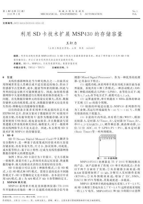
MSP430与MMC-SD卡接口使用
利用SD卡技术扩展MSP430的存储容量
7
DO
输出
数据输出
8
RSV
空置
9
RSV2
空置
图2 SD 卡与 MSP430单片机的接口图
3 协 议 分 析
SD 协议是一种简单的命令—应答协议,所有的命
以往的设 备 方 案 多 采 用 单 片 机 连 接 闪 存 芯 片 或 EEPROM 芯片,但该方案对于数据转存 PC 时 使 用 不 是很方便;另有报 导 使 用 U 盘 作 为 数 据 存 储,该 方 案 需要使用 USB 协议,耗 电 量 也 较 多,并 且 数 据 读 写 需 要 遵 循 文 件 系 统 的 相 关 协 议 ,编 程 量 大 ,对 于 一 般 简 单 的无线网络 节 点 不 是 太 适 合. 因 此,本 文 利 用 SD 卡 技术扩展 MSP430的存储容量. 1 SD 卡
图1 SD 卡结构图
MSP430F1611处 理 器 是 TI于 2003 年 期 间 推 出 的产品.该产品继 承 了 传 统 430 单 片 机 的 优 点,并 在 以下 两 个 方 面 有 了 发 展:① 从 存 储 器 方 面 来 说,将 RAM 容量增 加 到 了 10kB,方 便 引 入 实 时 操 作 系 统 (RTOS);② 从 外 围 模 块 来 说,增 加 了 I2C、DMA、 DAC12和 SVS等模块,其集成度进一步提高.
MSP430系列 单 片 机 是 美 国 德 州 仪 器 (TI)1996 年开始推向市场的一 种 16 位 超 低 功 耗 的 混 合 信 号 处
理 器 (MixedSignalProcessor). 作 为 一 种 优 秀 的 处 理 器 ,它 具 备 以 下 特 点 :
(1)超 低 功 耗 :该 系 列 单 片 机 在 功 耗 方 面 目 前 为 业 界最强.系统共 有6种 工 作 模 式:一 种 活 动 模 式 (AM) 和5种低功耗模式(LPM0~LPM4).在等待方式下,耗 电为0.7μA;在节电方式下,最低可达0.1μA.
MSP430FR 系列MCU 的多功能双接口存储器
Application Report ZHCA608 – June 20141基于MSP430FR 系列MCU 的多功能双接口存储器设计Triton Zhang, Hardy HuMCU FAE Team摘要在许多嵌入式系统中通常会需要外接存储器保存数据,例如EEPROM 。
由于传统的存储器具有功能单一、接口固定、擦写次数有限的特点从而限制了存储器的应用场景和范围。
本文介绍了一种基于TI 新一代MSP430FR 系列MCU 来实现多功能双接口存储器的方法。
相比传统存储器 (例如FLASH ,SRAM ,EEPOM),FRAM 集合了更多的优势,拥有更强大的功能。
利用MCU 的灵活性,用户可以设计出功能强大,接口灵活的多功能存储器,用来替代传统嵌入式系统中的EEPROM 和RTC 等功能。
目录摘要............................................................................................................................ 1 1 前言........................................................................................................................ 2 2 功能介绍................................................................................................................ 2 2.1 MSP430FRXX 系列MCU 简介 .................................................................... 2 2.2 FRAM 简介 ..................................................................................................... 2 2.3 MSP430FRXX 系列MCU 中FRAM 管理器简介 ....................................... 3 2.4 多功能双接口存储器系统功能简介 ............................................................. 3 2.5 多功能双接口存储器系统典型应用简介 ..................................................... 4 3 系统设计................................................................................................................ 7 3.1 系统框图 ......................................................................................................... 7 3.2 管脚定义 ......................................................................................................... 8 3.3 存储器分配 ..................................................................................................... 8 3.4 功能模块配置 ............................................................................................... 10 3.5 系统配置寄存器 ........................................................................................... 10 3.6 I2C 接口说明 ................................................................................................ 11 3.7 SPI 接口说明 ................................................................................................ 11 4 功能模块设计...................................................................................................... 11 4.1 铁电(FRAM)存储器 ..................................................................................... 11 4.1.1 I2C 接口访问 ......................................................................................... 12 4.1.2 SPI 接口访问 ......................................................................................... 12 4.2 RTC 模块 ...................................................................................................... 12 4.2.1 功能描述................................................................................................ 12 4.2.2 RTC 模块寄存器描述 ........................................................................... 12 4.3 AES 加密模块 .............................................................................................. 13 4.3.1 AES 加密/解密模块寄存器列表(基地址 : 0xF400) ............................ 13 4.3.2 AES 加密/解密模块控制寄存器(偏移地址 : 0x00) ............................ 13 4.4 电压检测器模块 ........................................................................................... 14 4.4.1 电压检测模块寄存器描述(基地址 : 0xF000)...................................... 14 4.4.2 电压检测模块控制寄存器(偏移地址 : 0x00) .. (14)ZHCA608基于MSP430FR系列MCU的多接口存储器设计24.4.3电压检测模块电压门限寄存器 VTRIPNX(16Bit) (14)4.5WDT模块 (15)4.5.1看门狗模块寄存器描述(基地址 : 0xEC00) (15)4.5.2看门狗模块控制寄存器(偏移地址 : 0x00) (15)4.5.3看门狗溢出周期寄存器 WDTN_VAL(32Bit) (16)5 软件设计 (16)5.1软件流程图 (17)6 参考文献 (17)1前言从2011年起,TI(德州仪器)公司先后推出了近20款带FRAM的MSP430系列MCU – MSP430FRXX。
msp430可通过哪些接口进行烧写程序

MSP430可通过哪些接口进行烧写程序?MSP430无论是仿真还是烧写程序,一般可以通过:JTAG、SBW、BSL接口进行。
1、JTAG是利用边界扫描技术,在430内部有逻辑接口给JTAG使用,内部有若干个寄存器连接到了430内部数据地址总线上,所以可以访问到430的所有资源,包括全地址FLASH、RAM及各种寄存器。
可以用于对430的仿真和编程,主要连接线有TMS、TCK、TDI、TDO,430还需要另两条线路RST、TEST来启动JTAG 命令序列。
2、SBW是SPY-BI-WIRE,可以简称为两线制JTAG,主要有SBWTCK(连接到JTAG接口的7脚TCK)与SBWTDIO(连接到JTAG接口的1脚TDO/TDI),该接口主要用于小于28脚的2系列单片机,因为28脚以内单片机的JTAG一般与IO口复用,为了给用于留有更多的IO资源,才推出SBW接口。
SBW同JTAG一样可以访问到430内部的所有资源。
注:目前MSP430F5XX系列中也有SBW 接口,原理同2系列的SBW。
3、BSL是TI在430出厂时预先固化到MCU内部的一段代码,该代码用户不可读写,这有点类似与DSP的bootloader,但又与bootloader有明显的区别,BSL只能用于对MCU内部的FLASH访问,不能对其他的资源访问,所以只能用作编程器接口。
BSL通过UART协议与编程器连接通信。
编程器可以发送不同的通信命令来对MCU的存储器做不同的操作,可以把这种方式称为BSL接口。
BSL代码的启动有些特殊,一般430复位启动时PC指针指向FFFE复位向量,但可以通过特殊的启动方式可以使MCU在启动时让PC指向BSL内部固化的程序。
这种特殊的启动方式一般是由RST引脚与TEST(或TCK)引脚做一个稍复杂的启动逻辑后产生。
BSL启动后,就可以通过预先定义好的UART协议命令对MCU进行读写访问了。
4、一般的MCU都有代码加密功能,430是如何实现的呢?外部对430内部的代码读写只能通过上述的三种方式,只要把这三种方式都堵上,430的程序不就安全了吗?所以又引入了熔丝位,熔丝位只存在于JTAG、SBW接口逻辑内。
利用MSP430在SD卡上实现FAT32文件系统

利用MSP430在SD卡上实现FAT32文件系统经过一周左右时间的摸索,终于明白了如何用msp30在SD卡实现FAT32文件系统,很开心~在学习的过程中,也发现一个问题,就是网上系统地讲SD卡的资料很少,而讲SDHC卡的资料则更少,所以决定写一篇博客与大家分享,由于SDHC卡大部分内容都与SD卡一样,所以下文除非是特别介绍SDHC卡,其余都会以SD卡代替SDHC卡。
如果发现文中存在问题,欢迎指正,谢谢。
首先,我们先说明一下本文的主要内容,本文的主要侧重点在于利用msp430(其它单片机应该类似)驱动SD卡。
驱动方式选用SPI方式,驱动成功之后,将FAT32文件系统移植过来。
所以如果想要仔细学习FAT32文件系统的,可以忽略本文了,想要快速地利用单片机在SD 卡上实现FAT32文件系统的,可以看一下。
大家可以交流一下。
一、开发之前的准备1、准备WinHex工具工欲善其事,必先利其器。
在开发之前,我们必须要先准备好需要的工具,除了相应的单片机开发平台,我们还需要一个很重要的工具,WinHex。
WinHex可以直接查看磁盘内部的16进制数据。
我们把SD卡用卡槽接到电脑上之后,打开WinHex,点击Tools--Open Disk,然后在Physical Media下选择自己的SD卡,即可打开自己的SD卡。
如下图所示。
这里需要注意的是,一定要在Physical Media下选自己的SD卡,这样看到才是物理地址,否则看到的是逻辑地址,可能会跟你的实际操作不一致,如你在地址为1024的地方写了一段数据,用WinHex在这里却看不到你写的数据。
2、SD卡和SDHC卡目前大家口头上经常说的是SD卡,但实际上,目前所用的大容量的卡其实均是SDHC卡。
SD的容量最大只能到2G,而SDHC卡的容量最小2G,最大32G。
所以,如果你的“SD卡”的容量超过2G了,那其实那是SDHC卡。
MPS430用户手册

IAR Embedded Workbench™Version3+ for MSP430™User's GuideLiterature Number:SLAU138AFJune2004–Revised June2014Contents Preface (6)1Get Started Now! (8)1.1Software Installation (9)1.2Flashing the LED (9)1.3Important MSP430Documents on the CD-ROM and Web (10)2Development Flow (11)2.1Overview (12)2.2Using KickStart (12)2.2.1Project Settings (13)2.2.2Using Math Library for MSP430(MSPMathlib)in IAR EW4305.60.1and Newer (14)2.2.3Additional Project Settings for MSP430L092and MSP430C092 (14)2.2.4Creating a Project From Scratch (16)2.2.5Additional Project Settings for Ultra-Low-Power Mode(LPMx.5)Debugging (17)2.2.6Password Protection for MSP430Devices (18)2.2.7Using an Existing IAR V1.x,V2.x,or V3.x Project (18)2.2.8Stack Management and.xcl Files (19)2.2.9How to Generate Texas Instruments.TXT(and Other Format)Files (19)2.2.10Overview of Example Programs (19)2.3Using C-SPY (19)2.3.1Breakpoint Types (19)2.3.2Using Breakpoints (22)2.3.3Using Single Step (22)2.3.4Using Watch Windows (23)3EnergyTrace™Technology (24)3.1Introduction (24)3.2Energy Measurement (24)3.3IAR Embedded Workbench®for MSP430Integration (24)3.3.1Debugging Devices With EnergyTrace++Technology Support (24)3.3.2Debugging Devices Without EnergyTrace++Technology Support (31)3.4Measuring Low-Power Currents (34)3.5EnergyTrace Technology FAQs (35)4Memory Protection Unit(MPU)and Intellectual Property Encapsulation(IPE) (37)A Frequently Asked Questions (38)A.1Hardware (39)A.2Program Development(Assembler,C-Compiler,Linker) (39)A.3Debugging(C-SPY) (41)B FET-Specific Menus (45)B.1Menus (46)B.1.1Emulator→Device Information (46)B.1.2Emulator→Release JTAG on Go (46)B.1.3Emulator→Resynchronize JTAG (46)B.1.4Emulator→Init New Device (46)B.1.5Emulator→Secure-Blow JTAG Fuse (46)B.1.6Emulator→Breakpoint Usage (46)2Contents SLAU138AF–June2004–Revised June2014Submit Documentation FeedbackCopyright©2004–2014,Texas Instruments IncorporatedB.1.7Emulator→Advanced→Clock Control (46)B.1.8Emulator→Advanced→Emulation Mode (46)B.1.9Emulator→Advanced→Memory Dump (47)B.1.10Emulator→Advanced→Breakpoint Combiner (47)B.1.11Emulator→State Storage Control (47)B.1.12Emulator→State Storage Window (47)B.1.13Emulator→Sequencer Control (47)B.1.14Emulator→"Power on"Reset (47)B.1.15Emulator→GIE on/off (47)B.1.16Emulator→Leave Target Running (47)B.1.17Emulator→Force Single Stepping (47)Revision History (48)3 SLAU138AF–June2004–Revised June2014Contents Submit Documentation FeedbackCopyright©2004–2014,Texas Instruments IncorporatedList of Figures1-1.Activate Project (9)1-2.Activate Project in Workspace Overview (10)2-1.L092Mode (14)2-2.C092Emulation Mode (15)2-3.C092Password (15)2-4.Enable Ultra-Low-Power Debug Mode (17)2-5.LPMx.5Notifications (18)2-6.JTAG Password (18)3-1.Pulse Density and Current Flow (24)3-2.Debug Session With EnergyTrace++Windows (25)3-3.Debug Options (26)3-4.Emulator Pulldown Menu With EnergyTrace++-Related Functions (27)3-5.Enabling the State Log Window (27)3-6.State Log Window With EnergyTrace++Data (28)3-7.State Log Summary With EnergyTrace++Data (28)3-8.Power Log Setup Window (28)3-9.Power Log Window With EnergyTrace++Data (29)3-10.Timeline With Power Log and State Graphs Disabled (29)3-11.Timeline With EnergyTrace++Data (30)3-12.Function Profiler With EnergyTrace++Data (30)3-13.Debug Session With EnergyTrace Windows (31)3-14.Emulator Pulldown Menu With EnergyTrace-Related Functions (32)3-15.Power Log Setup Window (32)3-16.Power Log Window With EnergyTrace Data (33)3-17.Timeline With Power Log Graph Disabled (33)3-18.Timeline With EnergyTrace Data (34)3-19.LPM3Current When Executing Under Debug Control (34)3-20.Release JTAG on Go Option in Emulator Pulldown Menu (35)3-21.LPM3Current When Executing with JTAG Signals Released (35)4-1.MPU Configuration Dialog (37)4List of Figures SLAU138AF–June2004–Revised June2014Submit Documentation FeedbackCopyright©2004–2014,Texas Instruments IncorporatedList of Tables2-1.Device Architecture,Breakpoints,and Other Emulation Features (20)5 SLAU138AF–June2004–Revised June2014List of Tables Submit Documentation FeedbackCopyright©2004–2014,Texas Instruments IncorporatedPrefaceSLAU138AF–June2004–Revised June2014Read This FirstAbout This ManualThis manual describes the use of IAR Embedded Workbench®(EW430)with the MSP430™ultra-low-power microcontrollers.How to Use This ManualRead and follow the instructions in the Get Started Now!chapter.This chapter provides instructions on installing the software,and describes how to run the demonstration programs.After you see how quick and easy it is to use the development tools,TI recommends that you read all of this manual.This manual describes only the setup and basic operation of the software development environment,but it does not fully describe the MSP430microcontrollers or the complete development software and hardware systems.For details of these items,see the appropriate TI and IAR™documents listed in RelatedDocumentation From Texas Instruments,Important MSP430Documents on the CD-ROM and Web.This manual applies to the use with Texas Instruments'MSP-FET430UIF,MSP-FET430PIF,and eZ430 development tools series.These tools contain the most up-to-date materials available at the time of packaging.For the latestmaterials(including data sheets,user's guides,software,and application information),visit the TI MSP430 web site at /msp430or contact your local TI sales office.Information About Cautions and WarningsThis book may contain cautions and warnings.CAUTIONThis is an example of a caution statement.A caution statement describes a situation that could potentially damage yoursoftware or equipment.The information in a caution or a warning is provided for your protection.Read each caution and warning carefully.MSP430,EnergyTrace are trademarks of Texas Instruments.6Read This First SLAU138AF–June2004–Revised June2014 IAR Embedded Workbench is a registered trademark of IAR Systems AB.Submit Documentation Feedback All other trademarks are the property of their respective owners.Copyright©2004–2014,Texas Instruments Incorporated Related Documentation From Texas Instruments Related Documentation From Texas InstrumentsMSP430development tools documentationMSP430Hardware Tools User's Guide,literature number SLAU278eZ430-F2013Development Tool User's Guide,literature number SLAU176eZ430-RF2480User's Guide,literature number SWRA176eZ430-RF2500Development Tool User's Guide,literature number SLAU227eZ430-RF2500-SEH Development Tool User's Guide,literature number SLAU273eZ430-Chronos Development Tool User's Guide,literature number SLAU292MSP430device data sheetsMSP430x1xx Family User's Guide,literature number SLAU049MSP430x2xx Family User's Guide,literature number SLAU144MSP430x3xx Family User's Guide,literature number SLAU012MSP430x4xx Family User's Guide,literature number SLAU056MSP430x5xx and MSP430x6xx Family User's Guide,literature number SLAU208MSP430FR57xx Family User's Guide,literature number SLAU272MSP430FR58xx,MSP430FR59xx,MSP430FR68xx,and MSP430FR69xx Family User's Guide,literature number SLAU367CC430device data sheetsCC430Family User's Guide,literature number SLAU259If You Need AssistanceSupport for the MSP430devices and the FET development tools is provided by the Texas Instruments Product Information Center(PIC).Contact information for the PIC can be found on the TI web site at/support.The Texas Instruments E2E Community support forums for the MSP430is available to provide open interaction with peer engineers,TI engineers,and other experts.Additional device-specific information can be found on the MSP430web site.NOTE:The KickStart kit is supported by Texas Instruments.Although the KickStart kit is a product of IAR,Texas Instruments provides the support for it.Therefore,please do not request support for KickStart from IAR.Consult the extensivedocumentation provided with KickStart before requesting assistance.7 SLAU138AF–June2004–Revised June2014Read This First Submit Documentation FeedbackCopyright©2004–2014,Texas Instruments IncorporatedChapter1SLAU138AF–June2004–Revised June2014Get Started Now!This chapter provides instruction on installing the software,and shows how to run the demonstration programs.Topic Page1.1Software Installation (9)1.2Flashing the LED (9)1.3Important MSP430Documents on the CD-ROM and Web (10)8Get Started Now!SLAU138AF–June2004–Revised June2014Submit Documentation FeedbackCopyright©2004–2014,Texas Instruments Incorporated Software Installation 1.1Software InstallationFollow the instructions on the supplied READ ME FIRST document to install the IAR EmbeddedWorkbench™KickStart kit.Read the file<Installation Root>\Embedded Workbenchx.x\430\doc\readme.htm from IAR for the latest information about the Workbench.The term KickStartrefers to the function-limited version of Embedded Workbench(including C-SPY™debugger).KickStart is supplied on the CD-ROM included with each FET,and the latest version is available from the MSP430 web site.The documents mentioned in the previous paragraph(and this document)can be accessed using:Start→Programs→IAR Systems→IAR Embedded Workbench KickStart for MSP430V3.KickStart is compatible with Windows2000(SP4),Windows XP(32bit and64bit),Windows Vista(32bit and64bit),and Windows7(32bit and64bit).However,the USB FET interface works with only Windows XP(32bit and64bit),Windows Vista(32bit and64bit),and Windows7(32bit and64bit).1.2Flashing the LEDThis section demonstrates on the FET the equivalent of the C-language"Hello World!"introductoryprogram.An application that flashes the LED is developed and downloaded to the FET,and then run.1.Start the Workbench(Start→Programs→IAR Systems→IAR Embedded Workbench KickStart forMSP430V3→IAR Embedded Workbench).2.Click File→Open Workspace to open the file at:<Installation Root>\Embedded Workbench x.x\430\FET_examples\Flashing the LED.eww.The workspace window opens.3.Click on the tab at the bottom of the workspace window that corresponds to the MSP430device(MSP430xxxx)and desired language(assembler or C)to set a project active(see Figure1-1).Figure1-1.Activate Project9 SLAU138AF–June2004–Revised June2014Get Started Now! Submit Documentation FeedbackCopyright©2004–2014,Texas Instruments IncorporatedImportant MSP430Documents on the CD-ROM and Web Alternatively,right click to activate a project in the Workspace Overview tab(see Figure1-2).Figure1-2.Activate Project in Workspace Overview4.Click Project→Options→FET Debugger→Setup→Connection to select the appropriate port:Texas Instruments LPT-IF for the parallel FET Interface(MSP-FET430PIF)or Texas Instruments USB-IF for the USB Interface(MSP-FET430UIF)or for the eZ430.5.Click Project→Rebuild All to build and link the source code.You can view the source code by double-clicking on the project,and then double-clicking on the displayed source file.6.Click Project→Debug to start the C-SPY debugger.C-SPY erases the device flash and thendownloads the application object file to the device flash.See FAQ Debugging#1if C-SPY is unable to communicate with the device.7.Click Debug→Go to start the application.The LED should flash.8.Click Debug→Stop Debugging to stop debugging,to exit C-SPY,and to return to the Workbench.9.Click File→Exit to exit the Workbench.Congratulations,you have just built and tested an MSP430application!1.3Important MSP430Documents on the CD-ROM and WebThe primary sources of MSP430information are the device-specific data sheet and user's guide.The most up-to-date versions of these documents that are available at the time of production are provided on the CD-ROM included with this tool.The MSP430web site(/msp430)contains the most recent version of these documents.PDF documents describing the IAR tools(Workbench and C-SPY,the assembler,the C compiler,thelinker,and the librarian)are in the common\doc and430\doc folders.Supplements to the documents(that is,the latest information)are available in HTML format in the same directories.430\doc\readme_start.htm provides a convenient starting point for navigating the IAR documentation.10Get Started Now!SLAU138AF–June2004–Revised June2014Submit Documentation FeedbackCopyright©2004–2014,Texas Instruments IncorporatedChapter2SLAU138AF–June2004–Revised June2014Development Flow This chapter describes how to use KickStart to develop application software and how to use C-SPY to debug it.Topic Page2.1Overview (12)2.2Using KickStart (12)2.3Using C-SPY (19)11 SLAU138AF–June2004–Revised June2014Development Flow Submit Documentation FeedbackCopyright©2004–2014,Texas Instruments IncorporatedOverview 2.1OverviewApplications are developed in assembler or C using the Workbench,and they are debugged using C-SPY.C-SPY is seamlessly integrated into the Workbench.However,it is more convenient to make thedistinction between the code development environment(Workbench)and the debugger(C-SPY).C-SPY can be configured to operate with the FET(that is,an actual MSP430device)or with a software simulator of the device.KickStart refers to the Workbench and C-SPY collectively.The KickStart software tools area product of IAR.Documentation for the MSP430family and KickStart is extensive.The CD-ROM supplied with this toolcontains a large amount of documentation describing the MSP430.The MSP430home page(/msp430)is another source of MSP430information.The components of KickStart(workbench and debugger,assembler,compiler,linker)are fully documented in<Installation Root>\EmbeddedWorkbench x.x\common\doc and<Installation Root>\Embedded Workbench\430\doc..htm files located throughout the KickStart directory tree contain the most up-to-date information and supplement the PDF files.In addition,KickStart documentation is available online via Help.Read Me First files from IAR and TI and this document can be accessed using Start→Programs→IAR Systems→IAR Embedded Workbench KickStart for MSP430V3.Tool User's Guide Most Up-To-Date Information Workbench,C-SPY EW430_UsersGuide.pdf readme.htm,ew430.htm,cs430.htm,cs430f.htmAssembler EW430_AssemblerReference.pdf a430.htm,a430_msg.htmCompiler EW430_CompilerReference.pdf icc430.htm,icc430_msg.htmC library CLibrary.htmLinker and Librarian xlink.pdf xlink.htm,xman.htm,xar.htm2.2Using KickStartThe KickStart edition is a special starter kit or evaluation version of IAR Embedded Workbench withlimitations both in code size and in the service and support that is provided.Limitations:•The C compiler does not generate an assembly code list file.•The code size limit of the MSP430IAR KickStart C/C++Compiler is set to4Kbytes for traditional MSP430devices and8Kbytes for MSP430X devices(see Table2-1for detailed information aboutwhich MSP430device is based on which architecture).•The IAR Assembler delivered is the full version without any restrictions.•The IAR XLINK Linker links a maximum of4Kbytes originating from C source code for traditional MSP430devices and8Kbytes for MSP430X devices(see Table2-1for detailed information aboutwhich MSP430device is based on which architecture),but an unlimited amount of code originatingfrom assembly code.•The IAR KickStart C-SPY Simulator reads a maximum of4Kbytes originating from C code for traditional MSP430devices and8Kbytes for MSP430X devices but is unlimited in the amount ofassembly code read(see Table2-1for detailed information about which MSP430device is based onwhich architecture).•MISRA C is not available.•The runtime library source code is not included.A full(that is,unrestricted)version of the software tools can be purchased from IAR.A mid-featured toolset–called Baseline,with a12Kbyte C-code size limitation and basic floating-point operations–is also available from IAR.See the IAR web site(www.iar.se)for more information.12Development Flow SLAU138AF–June2004–Revised June2014Submit Documentation FeedbackCopyright©2004–2014,Texas Instruments Incorporated Using KickStart 2.2.1Project SettingsThe settings required to configure the Workbench and C-SPY are numerous and detailed.Read andthoroughly understand the documentation supplied by IAR when dealing with project settings.Review the project settings of the supplied assembler and C examples(the project settings are accessed usingProject→Options with the project name selected).Use these project settings as templates whendeveloping your own projects.Note that if the project name is not selected when settings are made,the settings are applied to the selected file(not to the project).The following project settings are recommended or required:•Specify the target device(General Options→Target→Device).•Enable an assembler project or a C or assembler project(General Options→Target→Assembler-only project).•Enable the generation of an executable output file(General Options→Output→Output file→Executable).•To most easily debug a C project,disable optimization[C/C++Compiler→Optimizations→Size→None(Best debug support)].•Enable the generation of debug information in the compiler output(C/C++Compiler→Output→Generate debug information).•Specify the search path for the C preprocessor(C/C++Compiler→Preprocessor→Include Paths).•Enable the generation of debug information in the assembler output(Assembler→Output→Generate Debug Info).•Specify the search path for the assembler preprocessor(Assembler→Preprocessor→Include Paths).•To debug the project using C-SPY,specify a compatible format[Linker→Output→Format→Debug information for C-SPY(with runtime control modules or with I/O emulation modules)].•Specify the search path for any used libraries(Linker→Config→Search paths).•Specify the C-SPY driver.Select Project→Options→Debugger→Setup→Driver→FET Debugger to debug on the FET(that is,MSP430device).Select Simulator to debug on the simulator.If FETDebugger is selected,use Project→Options→FET Debugger→Setup→Connection to select theappropriate port:Texas Instruments LPT-IF for the parallel FET Interface(MSP-FET430PIF)or TexasInstruments USB-IF for the USB Interface(MSP-FET430UIF)or for the eZ430.•Enable the Device Description file.This file makes C-SPY"aware"of the specifics of the device it is debugging.This file corresponds to the specified target device(Debugger→Setup→Devicedescription file→Override default).•Enable the erasure of the Main and Information memories before object code download(FET Debugger→Download→Erase main and Information memory).•To maximize system performance during debug,disable Virtual Breakpoints(FET Debugger→Breakpoints→Use virtual breakpoints)and disable all System Breakpoints(FET Debugger→Breakpoints→System breakpoints on).NOTE:Use Factory Settings to quickly configure a project.Use the Factory Settings button to quickly configure a project to a usable state.The following steps can be used to quickly configure a project.Note that the General Options tab does not have a Factory Settings button.1.Specify the target device(General Options→Target→Device).2.Enable an assembler project or a C or assembler project(General Options→Target→Assembler-only project).3.Enable the generation of an executable output file(General Options→Output→Output file→Executable).4.Accept the factory settings for the compiler(C/C++Compiler→Factory Settings).5.Accept the factory settings for the assembler(Assembler→Factory Settings).13 SLAU138AF–June2004–Revised June2014Development Flow Submit Documentation FeedbackCopyright©2004–2014,Texas Instruments IncorporatedUsing KickStart 6.Accept the factory settings for the linker(Linker→Factory Settings).7.Accept the factory settings for C-SPY(Debugger→Factory Settings).8.Debug on the hardware(Debugger→Setup→Driver→FET Debugger).9.Specify the active parallel port used to interface to the FET if not LPT1(FET Debugger→Setup→Connection→Texas Instruments LPT-IF)or specify the USB port(FET Debugger→Setup→Connection→Texas Instruments USB-IF).NOTE:Avoid the use of absolute path names when referencing files.Instead,use the relative pathname keywords$TOOLKIT_DIR$and$PROJ_DIR$.See theIAR documentation for a description of these keywords.The use of relative path namespermits projects to be moved easily,and projects do not require modification when IARsystems are upgraded(for example,from KickStart or Baseline to Full).2.2.2Using Math Library for MSP430(MSPMathlib)in IAR EW4305.60.1and NewerTI's MSPMathlib is part of EW4305.60.1and newer releases.This optimized library provides up to26x better performance in applications that use floating point scalar math.For details,see the MSPMathlibweb page(/tool/mspmathlib).MSPMathlib may be enabled for new and existing projects on all supported devices.Enable or disable MSPMathlib in the project options(General Options→Library Configuration→MathLib).2.2.3Additional Project Settings for MSP430L092and MSP430C092The MSP430L092can operate in two different modes:L092mode and C092emulation mode.Thepurpose of the C092emulation mode is to behave like a C092with up to1920bytes of code at its final destination for mask generation.The operation mode is determined by EW430before starting the debugger.Two radio buttons areavailable for the mode selection.By default the L092mode is selected(see Figure2-1and Figure2-2).Figure2-1.L092Mode14Development Flow SLAU138AF–June2004–Revised June2014Submit Documentation FeedbackCopyright©2004–2014,Texas Instruments Incorporated Using KickStartFigure2-2.C092Emulation Mode2.2.3.1MSP430L092Loader CodeThe Loader Code in the MSP430L092is a ROM-code from TI that provides a series of services.It enables customers to build autonomous applications without needing to develop a ROM mask.Such an application consists of an MSP430device containing the loader(for example,MSP430L092)and an SPI memorydevice(for example,'95512or'25AA40);these and similar devices are available from variousmanufacturers.The majority of use cases for an application with a loader device and external SPI memory for native0.9-V supply voltage are late development,prototyping,and small series production.Figure2-1shows the selection for loading the application into the external SPI memory.2.2.3.2Password Protection of MSP430C092The MSP430C092is a customer-specific ROM device that is protected by a password.To start a debug session,the password must be provided to EW430.Figure2-3shows how to provide a HEX password in EW430.Figure2-3.C092Password15 SLAU138AF–June2004–Revised June2014Development Flow Submit Documentation FeedbackCopyright©2004–2014,Texas Instruments IncorporatedUsing KickStart 2.2.4Creating a Project From ScratchThis section presents step-by-step instructions to create an assembler or C project from scratch,and to download and run the application on the MSP430(see also Section2.2.1,Project Settings).The MSP430 IAR Embedded Workbench IDE User's Guide presents a more comprehensive overview of the process.1.Start the Workbench(Start→Programs→IAR Systems→IAR Embedded Workbench KickStart forMSP430V3→IAR Embedded Workbench).2.Create a new text file(File→New→File).3.Enter the program text into the file.NOTE:Use.h files to simplify your code development.KickStart is supplied with files that define the device registers and the bit names for eachdevice.These files can greatly simplify the task of developing your program.The files arelocated in<Installation Root>\Embedded Workbench x.x\430\inc.Include the.h filecorresponding to your target device in your text file(#include"msp430xyyy.h").Additionally,files io430xxxx.h are provided and are optimized to be included by C source files.4.Save the program text file(File→Save).It is recommended that assembler text files be saved with a file-type suffix of".s43"and that C text files be saved with a file-type suffix of".c".5.Create a new workspace(File→New→Workspace).6.Create a new project(Project→Create New Project).Select Tool chain:MSP430,Project Templates:Empty project and click OK.Specify a project name and click Save.7.Add the program text file to the project(Project→Add Files).Select the program text file and clickOpen.Alternatively,double-click on the file to add it to the project.NOTE:How to add assembler source files to your projectThe default file type presented in the Add Files window is"C/C++Files".To view assemblerfiles(.s43),select"Assembler Files"in the"Files of type"drop-down menu.8.Save the workspace(File→Save Workspace).Specify a workspace name and click Save.9.Configure the project options(Project→Options).For each of the subcategories(General Options,C/C++Compiler,Assembler,Linker,Debugger),accept the default Factory Settings with the followingexceptions:•Specify the target device(General Options→Target→Device).•Enable an assembler project or a C or assembler project(General Options→Target→Assembler-only project).•Enable the generation of an executable output file(General Options→Output→Output file→Executable).•To debug on the FET(that is,the MSP430),click Debugger→Setup→Driver→FET Debugger.•Specify the active port used to interface to the FET(FET Debugger→Setup→Connection).10.Build the project(Project→Rebuild All).11.Debug the application using C-SPY(Project→Debug).This starts C-SPY,and C-SPY takes control ofthe target,erases the target memory,programs the target memory with the application,and resets thetarget.See FAQ Debugging#1if C-SPY is unable to communicate with the device.12.Click Debug→Go to start the application.13.Click Debug→Stop Debugging to stop the application,to exit C-SPY,and to return to the Workbench.14.Click File→Exit to exit the Workbench.16Development Flow SLAU138AF–June2004–Revised June2014Submit Documentation FeedbackCopyright©2004–2014,Texas Instruments Incorporated Using KickStart 2.2.5Additional Project Settings for Ultra-Low-Power Mode(LPMx.5)Debugging2.2.5.1What is LPMx.5LPMx.5is an ultra-low-power mode in which the entry and exit is handled differently than the other low-power modes.LPMx.5gives the lowest power consumption available on a device.To achieve this,entry to LPMx.5disables the LDO of the PMM module,which removes the supply voltage from the core and the JTAGmodule of the device.Because the supply voltage is removed from the core,all register contents andSRAM contents are lost.Exit from LPMx.5causes a BOR event,which forces a complete reset of thesystem.NOTE:The option"RELEASE JTAG ON GO"is currently not supported in the EmbeddedWorkbench when LPMx.5debugging is active.See the MSP430device family user's guidefor additional LPMx.5and ultra-low-power debug mode details.2.2.5.2Enable Ultra-Low-Power Debug ModeTo enable the ultra-low power debug mode feature the“Enable ULP/LPMx.5debug”checkbox must be enabled by clicking FET Debugger->Setup->Enable ULP/LPMx.5debug(see Figure2-4).When the ultra-low power debug mode is enabled a notification is displayed in the Debugger log every time thetarget device enters and leaves LPMx.5mode(see Figure2-5).Press the Halt or Reset button in Embedded Workbench to wake up the target device from LPMx.5.Execution of the code is halted at the start of the program.All breakpoints that had been active beforeLPMx.5are restored and reactivated automatically.Figure2-4.Enable Ultra-Low-Power Debug Mode17 SLAU138AF–June2004–Revised June2014Development Flow Submit Documentation FeedbackCopyright©2004–2014,Texas Instruments Incorporated。
msp430可通过哪些接口进行烧写程序
MSP430可通过哪些接口进行烧写程序?MSP430无论是仿真还是烧写程序,一般可以通过:JTAG、SBW、BSL接口进行。
1、JTAG是利用边界扫描技术,在430内部有逻辑接口给JTAG使用,内部有若干个寄存器连接到了430内部数据地址总线上,所以可以访问到430的所有资源,包括全地址FLASH、RAM及各种寄存器。
可以用于对430的仿真和编程,主要连接线有TMS、TCK、TDI、TDO,430还需要另两条线路RST、TEST来启动JTAG 命令序列。
2、SBW是SPY-BI-WIRE,可以简称为两线制JTAG,主要有SBWTCK(连接到JTAG接口的7脚TCK)与SBWTDIO(连接到JTAG接口的1脚TDO/TDI),该接口主要用于小于28脚的2系列单片机,因为28脚以内单片机的JTAG一般与IO口复用,为了给用于留有更多的IO资源,才推出SBW接口。
SBW同JTAG一样可以访问到430内部的所有资源。
注:目前MSP430F5XX系列中也有SBW 接口,原理同2系列的SBW。
3、BSL是TI在430出厂时预先固化到MCU内部的一段代码,该代码用户不可读写,这有点类似与DSP的bootloader,但又与bootloader有明显的区别,BSL只能用于对MCU内部的FLASH访问,不能对其他的资源访问,所以只能用作编程器接口。
BSL通过UART协议与编程器连接通信。
编程器可以发送不同的通信命令来对MCU的存储器做不同的操作,可以把这种方式称为BSL接口。
BSL代码的启动有些特殊,一般430复位启动时PC指针指向FFFE复位向量,但可以通过特殊的启动方式可以使MCU在启动时让PC指向BSL内部固化的程序。
这种特殊的启动方式一般是由RST引脚与TEST(或TCK)引脚做一个稍复杂的启动逻辑后产生。
BSL启动后,就可以通过预先定义好的UART协议命令对MCU进行读写访问了。
4、一般的MCU都有代码加密功能,430是如何实现的呢?外部对430内部的代码读写只能通过上述的三种方式,只要把这三种方式都堵上,430的程序不就安全了吗?所以又引入了熔丝位,熔丝位只存在于JTAG、SBW接口逻辑内。
MSP430串口通信讲解
串行通信接口是处理器与外界进行数据传输最常用的方式之一。
顾名思义,串行通信是指使用一条数据线,将数据一位一位地依次传输,每一位数据占据一个固定的时间长度。
与并行通信相比,串行通信速度较慢,但占用更少的I/O 资源,只需要少数几条线就可以在系统间交换信息,特别适用于计算机与计算机、计算机与外设之间的远距离通信。
串行通信可以分为同步通信和异步通信两种类型。
如果带有同步时钟,则称为同步串行通信,如常用的 SPI 和 I2C 接口就属于同步串行通信接口。
如果没有同步时钟,依靠严格的时间间隔来传输每一比特,则称为异步串行通信。
MSP430 系列单片机有两种串行通信接口,较早的 USART 模块和较新的 USCI 模块。
同步通信方式,是把许多字符组成一个信息组,这样,字符可以一个接一个地传输。
但是,在每组信息(通常称为信息帧)的开始要加上同步字符,在没有信息要传输时,要填上空字符,因为同步传输不允许有间隙。
同步方式下,发送方除了发送数据,还要传输同步时钟信号,信息传输的双方用同一个时钟信号确定传输过程中每1位的位置。
在异步通信方式中,两个数据字符之间的传输间隔是任意的,所以,每个数据字符的前后都要用一些数位来作为分隔位。
MSP430G2553单片机USCI模块原理图串口通信所需配置:1、时钟选择——以SMCLK时钟频率为1MHz为例。
①选择SMCLK为串口通信频率。
(P95页)②设置SMCLK时钟频率为1MHz。
需要设置的寄存器:UCA0CTL1;(P95页)。
2、IO口定义为第二功能,即串口发送接收端口。
需要设置的寄存器:P1SEL|=BIT1+BIT2;,P1SEL2|=BIT1+BIT2;(中文P44页)。
2、数据传输格式本次实验数据格式设置为:1位起始位8位数据位无奇偶校验1为停止位需要设置的寄存器:UCA0CTL0(P94页)3、设置波特率,以9600为例。
需要设置的寄存器:UCA0BR0,UCA0BR1,UCA0MCTL。
msp430单片机教程
msp430单片机教程MSP430单片机是一种经典的低功耗、高性能的微控制器,被广泛应用于嵌入式系统中。
它具有很多特点,比如低功耗、宽工作电压范围、快速启动速度等。
本文将介绍MSP430单片机的基本知识和使用方法。
首先,我们需要了解MSP430单片机的结构。
MSP430包括CPU、内存、I/O接口等多个部分。
CPU是控制单元,负责处理指令和数据。
内存是存储器,用于存储程序和数据。
I/O接口用于与外部设备进行通信。
MSP430单片机使用C语言进行编程。
编程的基本步骤包括初始化、读取输入、处理数据、输出结果等。
编程时,需要了解寄存器的使用方法和I/O接口的配置。
MSP430提供了丰富的库函数和工具,方便开发人员进行程序开发和调试。
MSP430单片机的应用范围广泛。
它可以用于物联网设备、传感器、控制器、无线通信等多个领域。
由于其低功耗的特点,MSP430单片机在电池供电设备中得到了广泛应用。
其性能优越和易用性也使得它成为嵌入式系统中的首选单片机。
MSP430单片机教程包括了一系列基础和高级的内容。
基础教程首先介绍了MSP430单片机的基本知识,包括硬件结构、编程环境和工具的使用等。
然后,通过一系列实践案例,教授学生如何编写简单的程序。
高级教程则深入讲解了MSP430单片机的一些高级特性和应用,如中断、定时器、串口通信等。
在学习MSP430单片机时,还需要学习如何使用开发板和调试工具。
开发板是连接MSP430单片机和计算机的桥梁,提供了丰富的外设接口。
通过合理配置开发板,可以实现多种外设的功能。
调试工具可以帮助开发人员进行程序的调试和性能优化,提高开发效率和质量。
总之,MSP430单片机是一种功能强大、易用且低功耗的微控制器。
学习MSP430单片机的教程可以帮助我们掌握嵌入式系统的开发和应用。
通过学习,我们可以深入了解MSP430单片机的原理和使用方法,为实际应用提供有力的支持。
基于MSP430单片机的SD卡读写
作者简介:段勇(1983-),男,硕士研究生,研究方向为医用电子技术。
△通讯作者:chenzhcheng @ 。
基于MSP430单片机的SD 卡读写段勇,陈真诚△,宋含(中南大学信息物理工程学院生物医学工程研究所,湖南长沙410083)摘要:利用S D 卡研究、设计一种大容量心电存储及回放系统。
系统基于高速低功耗的msp430单片机,利用串行外围接口总线与S D 卡相连,实现对S D 卡的数据读写。
为方便微处理器和pc 机对S D 卡的操作,在S D 卡中以fat16文件格式建立了相应的文件系统。
能够利用S D 卡中保存的数据,通过点阵式液晶显示模块,完成心电波形的回放。
将该设计应用于便携式心电监护仪上,经实验,完全满足了200H z 心电采样频率的要求,实现了对12位AD 转换数据的实时保存、显示与回放。
关键词:S D 卡;MSP430;串行外设协议;文件分配表中图分类号:R318 文献标识码:A 文章编号:167226278(2007)0420347204R ead ΠWrite SD C ard based on Microcontroller MSP 430DUAN Yong ,CHEN Zhen 2cheng ,SONG H an(Institute o f Biomedical Engineering ,School o f Info -physics ,Central South Univer sity ,Changsha 410083,China )Abstract :A system of storing and re 2displaying ECG based on S D card was designed.Based on microcontroller MSP430with high speed and ultra -low power ,the im plementation of data write Πread to Πfrom S D card ,which is connected with serial peripheral inter face was introduced in the system .The file system in the S D card was FAT 16,which is convenient for the microcontroller and PC to communicate with the S D card.ECG data storaged in S D card could be displayed on the LC D in waveform.This design can be used in a portable ECG H olter system,which can com pletely satis fy the requirement of 200H z sam pling frequency through the experiment and can storage 、display and playback 12bit results of A ΠD conversion in real -time.K ey w ords :Secure digital card ;MSP430;Serial peripheral inter face (SPI );File allocation table (FAT )1 引 言心血管疾病是威胁人类健康的常见疾病之一,而一些异常的心电信号(如心律不齐,心肌梗塞等)只是在某些特定情况下才能出现,传统的心电图机只是短时间的心电采集和记录,一般很难捕捉到有价值的心电信息,从而导致错误的诊断。
MSP430通用串口的应用
第7章通用串口的应用7.1 串行通信的基本知识计算机系统与外部的信息交换称为通信。
通信方式主要有并行与串行两种方式。
并行通信是指通信数据的各数据位在多条线上同时被传输,以字或字节为单位并行进行。
并行通信速度快,但用的通信线多、成本高,故不宜进行远距离通信。
串行通信是指使用一条数据线,将数据一位一位地依次传输,每一位数据占据一个固定的时间长度。
其只需要少数几条线就可以在系统间交换信息,特别适用于计算机与计算机、计算机与外设之间的远距离通信。
根据信息的传送方向,串行通讯可以进一步分为单工、半双工和全双工三种。
信息只能单向传送为单工;信息能双向传送但不能同时双向传送称为半双工;信息能够同时双向传送则称为全双工。
串行通讯又分为异步通讯和同步通讯两种方式。
同步通信是一种连续串行传送数据的通信方式,一次通信只传送一帧信息。
这里的信息帧与异步通信中的字符帧不同,通常含有若干个数据字符。
它们均由同步字符、数据字符和校验字符(CRC)组成。
其中同步字符位于帧开头,用于确认数据字符的开始。
数据字符在同步字符之后,个数没有限制,由所需传输的数据块长度来决定;校验字符有1到2个,用于接收端对接收到的字符序列进行正确性的校验。
同步通信的缺点是要求发送时钟和接收时钟保持严格的同步。
异步通信中,在异步通信中有两个比较重要的指标:字符帧格式和波特率。
数据通常以字符或者字节为单位组成字符帧传送。
字符帧由发送端逐帧发送,通过传输线被接收设备逐帧接收。
发送端和接收端可以由各自的时钟来控制数据的发送和接收,这两个时钟源彼此独立,互不同步。
接收端检测到传输线上发送过来的低电平逻辑"0"(即字符帧起始位)时,确定发送端已开始发送数据,每当接收端收到字符帧中的停止位时,就知道一帧字符已经发送完毕。
图7.1 MAX232典型连接图最常见的串行通信标准有RS232、RS485、SPI和I2C等。
其中RS232和RS485均是美国电子工业协会EIA(Electronic Industry Association)制定的串行物理接口标准。
- 1、下载文档前请自行甄别文档内容的完整性,平台不提供额外的编辑、内容补充、找答案等附加服务。
- 2、"仅部分预览"的文档,不可在线预览部分如存在完整性等问题,可反馈申请退款(可完整预览的文档不适用该条件!)。
- 3、如文档侵犯您的权益,请联系客服反馈,我们会尽快为您处理(人工客服工作时间:9:00-18:30)。
微控技术论坛翻译义工文章MSP430与MMC、SD存储卡接口应用翻译: DC 微控技术论坛版主原文: Texas Instruments SLAA281B.pdf 此翻译只供参考,一切以原文为准. 最后更新日期2008.5.9.1 硬件描述MSP430通过SPI接口与MMC 或SD卡实现话。
SPI是快速和高效协议标准,他准许双向数据同时传送。
利用MSP430 USART模块的SPI实现串行数据的发送和接收。
图1中是主机和从机的硬件联接配置图,电路工作在单电源电压。
MSP430161x器件的P5.3和5.4引脚配置为GPIO使用,分别联接到SD卡的片选引脚和存储卡s插入检测引脚。
利用MSP430F161x的USART1硬件模块配置为3线的SPI模式,MSP430的P5.1、P5.2、P5.3引脚分别定义为SIMO1、SOMI1、UCLK1功能引脚并联接到MMC或SD卡。
2 软件描述软件代码和相关文件是基于在上面的硬件连接方式的来使用的。
那程序代码已写成模块化,并且可以直接调用。
注意只有一个有效卡命令子集可以使用,基于SPI接口的局限性和SD卡功能可靠性。
例子main()函数是举例说明那驱动函数的正确的使用。
用mmcinit()函数初始化那MSP430F161x为3线SPI 模式。
MSP430当检测到MMC卡的存在和尝试读到器件存储器大小时,MSP430准备了512个字节的数据缓冲区,并把卡中两个不同扇区的信息写入缓冲区。
最后,msp430读写在每一个存储区域的数据返回值。
After uncommenting the code line:// #define withDMAMSP430F161x DMA模块是使用在MSP430和MMC卡之间的数据传输,这将提高通讯速度和减少CPU 的负担。
如果软件要适合不同的USART模块使用或其他不同型号器件的USART模块使用时。
那么下面几个函数是必须要检查其正确的设置。
Void initSPI(void)Char mmcinit(void)mmc.h 文件3 功能描述3.1 char mmcinit(void);初始化MSP430端口、SPI、MMC卡。
如果那库文件要适用其他MSP430型号或其他USART模块,这例程的程序可能需要调整。
同样,一些控制信号不同的端口也要做相应的调整。
参量:无返回值:状态错误/成功代码3.2 char mmcping(void);检查假如MCC卡是存在的。
参量:无返回值:状态错误/成功代码3.3 Void mmcSendCmd (const char cmd,unsigned long data,const char crc);发送一个命令到MMC卡参量:cmd 表示命令将传送给MMC卡data 命令的数据crc 命令校验和返回值:无3.4 char mmcGole();设置MMC卡当前为空闲模式参量:无返回值:状态错误/成功代码3.5 char mmcSetBlockLength (contest unsigned long);设置MMC块的计数长度=2n字节。
通常这命令是不必用的。
默认块的长度为512字节。
参量:块长度计数=2n字节返回值:状态错误/成功代码3.6 char mmcReadBlock(const unsigned long address,const unsigned long count,unsigned char *pBuffer);#define mmcReadSector(sector,pBuffer) mmcReadBlock(sector x512,512,pBuffer)从一个指定的地址开始读一个大块字节数据。
参量:address 在卡上的开始地址的值count 读字节的数量pBuffer 指向读数据的缓冲区返回值:状态错误/成功代码3.7 char mmcWriteBlock (const unsigned long address, const unsigned long count, unsigned char *pBuffer);#define mmcReadSector(sector, pBuffer) mmcReadBlock(sector 512, 512, pBuffer)从一个指定的地址开始将顺序的数据写入块(512字节)参量:address 往卡写的数据的开始地址Count 写字节数量PBuffer 指向写数据的缓冲区返回值:状态错误/成功代码3.8 char mmcReadRegister(const char cmd_register; const unsigned char length, unsigned char *pBuffer);读内部arg1寄存器和长arg2寄存器参量:cmd_register 往卡写的数据的开始地址Length 读字节数量PBuffer 指向读的缓冲区返回值:状态错误/成功代码3.9 nusigned long mmcReadCardSize(void);读卡的空间大小,从CSD寄存器参量:无返回值:检测到卡的大小4 参考文献1. MSP430x169 Mixed Signal Microcontroller Data Sheet (SLAS368)2. MSP430x1xx Family User’s Guide (SLAU049)3. SanDisk MultiMediaCard Product Manual (SanDisk, 2001)5 MSP430与MMC 卡演示主程序原程序作者:S. Schauer Texas Instruments, Inc#include <msp430x16x.h>#include <hal_hardware_board.h>#include <mmc.h>#include <stdio.h>unsigned long cardSize = 0;unsigned char status = 1;unsigned int timeout = 0;int i = 0;unsigned char buffer[512];int main( void ){WDTCTL = WDTPW + WDTHOLD;//Initialisation of the MMC/SD-cardwhile (status != 0) // if return in not NULL an error did occur and the// MMC/SD-card will be initialized again{status = mmcInit();timeout++;if (timeout == 150) // Try 50 times till error{//printf ("No MMC/SD-card found!! %x\n", status);break;}}while ((mmcPing() != MMC_SUCCESS)); // Wait till card is inserted// Read the Card Size from the CSD RegistercardSize = mmcReadCardSize();// Clear Sectors on MMCfor (i = 0; i < 512; i++)buffer[i] = 0;mmcWriteSector(0, buffer); // write a 512 Byte big block beginning at the (aligned) adress for (i = 0; i < 512; i++)buffer[i] = 0;mmcWriteSector(1, buffer); // write a 512 Byte big block beginning at the (aligned) adress mmcReadSector(0, buffer); // read a size Byte big block beginning at the address.for (i = 0; i < 512; i++)if(buffer[i] != 0)P1OUT |= 0x01;mmcReadSector(1, buffer); // read a size Byte big block beginning at the address.for (i = 0; i < 512; i++)if(buffer[i] != 0)P1OUT |= 0x02;// Write Data to MMCfor (i = 0; i < 512; i++) buffer[i] = i;mmcWriteSector(0, buffer); // write a 512 Byte big block beginning at the (aligned) adress for (i = 0; i < 512; i++) buffer[i] = i+64;mmcWriteSector(1, buffer); // write a 512 Byte big block beginning at the (aligned) adress mmcReadSector(0, buffer); // read a size Byte big block beginning at the address.for (i = 0; i < 512; i++)if(buffer[i] != (unsigned char)i)P1OUT |= 0x04;mmcReadSector(1, buffer); // read a size Byte big block beginning at the address. for (i = 0; i < 512; i++)if(buffer[i] != (unsigned char)(i+64))P1OUT |= 0x08;for (i = 0; i < 512; i++)mmcReadSector(i, buffer); // read a size Byte big block beginning at the address. mmcGoIdle(); // set MMC in Idle modewhile (1);}6 全套例程的下载全套例程请通过以下链接下载:/cn/lit/an/slaa281b/slaa281b.zipusage_example_IAR文件夹MMC_lib文件夹。