2020年ABB控制系统更新说明
ABB系统概述第二种版本

X.B
Input/Output Channel
系统介绍:网络结构 Network Architecture
Symphony 系统不同网络结构采用的通讯协议
Cnet
存储 转发 通讯 协议
C.W
自由 竞争 通讯 协议
X.B
没有 标称 通讯 协议
XB
I/O N P M N P M M F P M F P B R C B R C I/O I/O
RIO
RIO
I/O
3,000m
C.W X.B
处理器模件 通道子模件
32 64
1Mbaud 0.5Mbyte
一个HCU 一个处理器
印刷电路 印刷电路
SYMPHONY 系统介绍 Page 24
系统介绍:网络结构 Network Architecture
北京ABB贝利培训中心
ABB Bailey Beijing Training Center
培训中心介绍
培训地点:电子城科技大厦第十二层1208 教室分布:可占用第1、2、3教室 就餐地点:电子城科技大厦-1层 培训人员:培训中心主任:赵树谦
教员分工: 赵树谦老师承担控制策略/人系统接口操作、组态课程; 董补全老师承担控制软件及策略/人系统接口组态课程; 高建华老师承担过程控制单元硬件/主要系统模件课程; 成 虎老师承担培训支持及系统结构/通讯结构等课程;
SYMPHONY 系统介绍 Page 8
北京ABB贝利培训中心
ABB总机:84566688
系统部经理 系统部助理 项目经理部经理 项目经理部助理
ABB Bailey Beijing Training Center
培训中心前厅:64357302
ABB AbilityTM EDCS Ekip E-Hub 产品介绍说明书
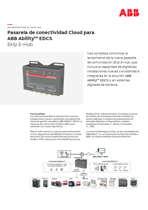
—I N FO M A R K E TI NG EL 2020-303Pasarela de conectividad Cloud para ABB Ability TM EDCS Ekip E-HubNos complace comunicar ellanzamiento de la nueva pasarela de comunicación Ekip E-Hub, que incluye la capacidad de digitalizar instalaciones nuevas o existentes e integrarlas en la solución ABB Ability TM EDCS o en sistemas digitales de terceros.FuncionalidadLa nueva pasarela Ekip E-Hub permite conectar instalaciones nuevas o existentes a la plataforma Cloud de gestión energética ABB ABility TM EDCS o a sistemas de control tipo SCADA o BMS, para optimizar sus costes operativos.Ekip E-Hub reconoce y conecta automáticamente con los dispositivos de ABB Electrification a través del puerto de conectividad Ethernet (protocolo Modbus TCP) y del puerto serie RS485 (protocoloModbus RTU). Adicionalmente, el módulo opcional de señales de entrada permite leer medidas de pulsos digitales o estados de la aparamenta (6 entradas digitales configurables) y señales analógicas (2 entradas 4…20mA y 2 entradas 0…36V).La conectividad aguas arriba, ya sea a la plataforma ABB Ablity TM o a un sistema de control tipo SCADA oBMS, se realiza mediante el puerto Ethernet.Módulos enchufables Ekip Com como alternativa Los módulos enchufables Ekip Com son unaalternativa en aquellos casos donde sea posible el uso de dispositivos como Emax 2, Tmax XT, Ekip UP o TruONE ATS. En este caso, Ekip Com Hub permite la conexión a ABB Ability TM EDCS y Ekip Com Modbus TCP (u otros módulos Ekip Com con protocolos de comunicación estándares) permite la conexión a sistemas de control tipo SCADA o BMS.Configuración y puesta en marchaLa herramienta de configuración de la nuevapasarela Ekip E-Hub es el software Ekip Connect, una herramienta gratuita de configuración, supervisión y diagnóstico para otras gamas de producto como Emax 2, Tmax XT, Ekip UP, M4M, TruONE ATS, etc.Ekip Connect reconoce automáticamente la pasarela Ekip E-Hub, conectando el PC al puerto Ethernet del dispositivo.Ekip Connect Ekip E-HubEn cuanto a dimensiones:Características técnicas Alimentación 9…36 V DCMontaje Carril DIN 35mm (DIN EN 60 715)IPIP40Temperatura de trabajo -20…+70ºCDimensiones 198,0 x 90,3 x 48,4 mm Norma IEC62368-1Antena 3G Opcional (necesarias 2uds)Memoria interna4GB eMMCConectividadPuertos y protocolos2x RJ45 Ethernet – Modbus TCP2x RS-485 - Modbus RTU 2x USB 2.02x MicroSIM – 3G (no suministrada)Módulo opcional E/S6x Entradas digitales 24 V DC 4x Entradas analógicasCaracterísticas principalesLas características técnicas principales de la nueva pasarela Ekip E-Hub son:—01Ejemplo conectividadcon los dispositivos deprotección, medida ygestión de la energía—01—(*) Únicamente se muestran los códigos incluidos en tarifa PDF 2020. Parael resto de códigos y precios consultar la tarifa electrónica o PDC.Códigos de pedido (*)Código pedido Descripción Precio unit. €GTV ABC Sum.mín./Embalaje Ud ConectividadI N F O M A R K E T I N G E L 2020-303Haga click en la imagen para acceder a la documentaciónHaga click en la imagen para acceder a la documentación—Manual técnico Ekip E-HubPresentación PDF de lanzamiento Ekip E-HubHaga click en la imagen para acceder a la webPágina web soluciones digitales de supervisión de la energíaHaga click en la imagen para acceder a la documentaciónManual usuario Ekip E-Hub Haga click en la imagen para acceder a la documentaciónFolleto ABB ABility TM EDCS—Pau MasgrauABB Ability™ Market Development ManagerAsea Brown Boveri, SA Low Voltage Products Tel.: 93 484 22 25Fax: 93 484 21 90www.abb.es/bajatension。
ABB 网络保护与控制产品说明书

-Conceptional overview diagrams -Necessary overview panels -Layout of mimic panels
-Specification and adressing of signals -MMI pictures of switchgear components
-Logic diagrams
-Documentation
on system configuration and
settings -Different connecting diagrams
If requested, the drawings Iisted above are submitted to the customer for review and approval.
ABB Relays is able to render assistance and
recommendations during the preparation of concepts and specifications for protection and controi systems. ABB Relays can also assist the customer with network studies and calculations.
ABB Network Controi & Protection
.
1MDBOOOO3-EN
Page 1 March 1992 Changed since August 1990 Data subject to change without
natice
Relays Systems
~Ab' röäffrängeö{protectivereläYSforgenera- ~cluded in this Buyer's Guide and can easily
ABB SM500F 分析器数据记录器模块板升级包安装说明说明书
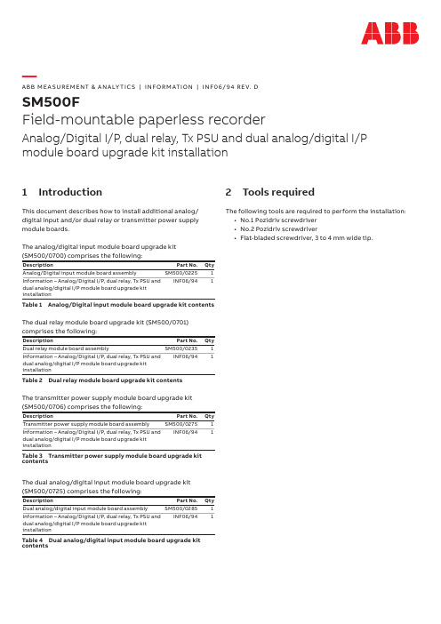
—A B B M E A SU R EM ENT & A N A LY TI C S | I N FO R M ATI O N | I N F06/94 R E V. DSM500FField-mountable paperless recorderAnalog/Digital I/P, dual relay, Tx PSU and dual analog/digital I/P module board upgrade kit installation1 IntroductionThis document describes how to install additional analog/ digital input and/or dual relay or transmitter power supply module boards.The analog/digital input module board upgrade kit(SM500/0700) comprises the following:Description Part No.Qty Analog/Digital input module board assembly SM500/02251 Information – Analog/Digital I/P, dual relay, Tx PSU anddual analog/digital I/P module board upgrade kitinstallationINF06/941 Table 1 Analog/Digital input module board upgrade kit contentsThe dual relay module board upgrade kit (SM500/0701) comprises the following:Description Part No.Qty Dual relay module board assembly SM500/02351 Information – Analog/Digital I/P, dual relay, Tx PSU anddual analog/digital I/P module board upgrade kitinstallationINF06/941 Table 2 Dual relay module board upgrade kit contentsThe transmitter power supply module board upgrade kit (SM500/0706) comprises the following:Description Part No.Qty Transmitter power supply module board assembly SM500/02751 Information – Analog/Digital I/P, dual relay, Tx PSU anddual analog/digital I/P module board upgrade kitinstallationINF06/941Table 3 Transmitter power supply module board upgrade kit contentsThe dual analog/digital input module board upgrade kit(SM500/0725) comprises the following:Description Part No.Qty Dual analog/digital input module board assembly SM500/02851 Information – Analog/Digital I/P, dual relay, Tx PSU anddual analog/digital I/P module board upgrade kitinstallationINF06/941Table 4 Dual analog/digital input module board upgrade kit contents 2 Tools requiredThe following tools are required to perform the installation:• No.1 Pozidriv screwdriver• No.2 Pozidriv screwdriver• Flat-bladed screwdriver, 3 to 4 mm wide tip.2S M500F| M O D U L E B OA R D U P G R A D E K IT I NS TA L L ATI O N | I N F06/94 R E V. D 3Installing a module boardReferring to Figure 1, install an analog/digital input, dual relay or transmitter PSU module board as follows:1 Unlock the instrument door with the key supplied, press therelease catch and open the door.2 Remove the tamper-evident seal (if fitted), release thecaptive screw securing the inner cover plate and remove the inner cover plate.3 Identify the module board position (see Figure 2.8 on page17 of the User Guide, IM/SM500F). Align the connectors onthe module board and the motherboard and press home,ensuring the connectors engage correctly.Note.The dual relay module board or the transmitter power supply module board must be fitted only in position D.4 Secure the module board with the M3 x 16 screw.Note.Connect the module board as detailed in Sections 2.3 and 2.4 of the User Guide, IM/SM500F.5 Locate the inner cover plate lugs in the slots in the outercase and close the inner cover plate.6 Tighten the inner cover plate retaining screw and fit atamper-evident seal (if required).7 Close and lock the instrument door and restore the powersupply to the instrument.Figure 1 Installing an analog/digital input, dual relay or transmitter power supply module boardS M500F| M O D U L E B OA R D U P G R A D E K IT I NS TA L L ATI O N | I N F06/94 R E V. D3 4 NotesI N F 06/94 R e v . D 07.2019—We reserve the right to make technical changes or modify the contents of this document without prior notice. With regard to purchase orders, the agreed particulars shall prevail. ABB does not accept any responsibility whatsoever for potential errors or possible lack of information in this document.We reserve all rights in this document and in the subject matter and illustrations contained therein. Any reproduction, disclosure to third parties or utilization of its contents – in whole or in parts – is forbidden without prior written consent of ABB.© ABB 2019—ABB LimitedMeasurement & Analytics Howard Road St. NeotsCambridgeshire PE19 8EU UKTel: +44 (0)1480 475 321Fax: +44 (0)1480 217 948Email: **********************.comABB Inc.Measurement & Analytics 125 E. County Line Road Warminster PA 18974USATel: +1 215 674 6000Fax: +1 215 674 /measurement。
ABB FSO-12 -21 安全功能模块固件更新指南说明书

—OPTIONEN FÜR ABB FREQUENZUMRICHTERFSO-12/-21 - Firmware-Aktualisierung mit dem Drive Composer Pro BenutzerhinweiseFSO-12/-21 - Firmware-Aktualisierung mit dem Drive Composer ProBenutzerhinweise© 2020 ABB Oy. Alle Rechte vorbehalten. 3AXD50000578764 Rev ADEÜbersetzung des Originaldokuments3AXD50000564767 Rev AGÜLTIG AB: 2019-11-25Inhalt1. Einleitung (4)2. Voraussetzungen (4)3. Aktualisierung des FSO-12/-21 Sicherheitsfunktionsmoduls (5)3.1 Anschließen (5)3.2 Aktualisierung des Moduls mit dem Drive Composer Pro (5)3.3 Einstellung der FSO-Parameter (9)3.4 Validierung der Sicherheitsfunktionen (12)Weitere Informationen (13)1. EinleitungDieses Dokument beschreibt die Anforderungen und die Vorgehensweise bei der Aktualisierung der Firmware der Sicherheitsfunktionsmodule FSO-12 und FSO-21 mit der Software Drive Composer Pro. Durch das Update wird die Firmware der FSO-Module auf Version H, V4.3.0.0. aktualisiert. Version H behebt einen sicherheitskritischen Fehler in der Funktion Sicher Begrenzte Drehzahl (SLS) und dem PROFIsafe Modulationsstatusbit, der bei den Software-Versionen A-G der FSO-12/-21 Module besteht. Die Aktualisierung erfolgt bei den Sicherheitsfunktionsmodulen FSO-12 und -21 auf die gleiche Weise und dauert etwa 25 Minuten pro FSO-Modul.Hinweis! Es kann immer nur jeweils ein FSO-Modul aktualisiert werden.Hinweis! Diese Anweisung gilt nicht für die Aktualisierung der FSO-11 Sicherheitsoptionsmodule.Ergänzende HandbücherWeitere Informationen zur neuen FSO-Firmware finden Sie in den folgenden Benutzerhandbüchern:Dokument CodeOptionshandbücherFSO-12 safety functions module user’s manual3AXD50000015612FSO-21 safety functions module user’s manual3AXD50000015614 Handbuch des Drive PC-ToolsDrive composer Start-up and maintenance PC tool user’s manual3AUA0000094606Handbücher und andere Produktdokumente im PDF-Format finden Sie im Internet. Siehe /drives/documents. Wenden Sie sich bei Handbüchern, die nicht in der Dokumentenbibliothek verfügbar sind, an Ihre lokale ABB-Vertretung.Weitere Sicherheitsinformationen und Lösungen von ABB finden Sie unter /safety.2. VoraussetzungenLaden Sie vor der Aktualisierung zunächst die Software Drive Composer Pro 2.4.1 über den folgenden Link herunter. Der Drive Composer Pro 2.4.1 läuft mit Ihrem aktuellen Lizenzcode für den Drive Composer Pro (DCPT-01). Wenn Sie keine Lizenz für den Drive Composer Pro besitzen, kann die Software 30 Tage lang im Testmodus genutzt werden.Link zum Herunterladen des Drive Composer Pro 2.4.1:https:///drives/software-tools/drive-composerZusätzlich zum Drive Composer Pro 2.4.1 benötigen Sie folgende Ausrüstung:Kabel USB A auf USB Mini-B▪IBM-kompatibler PC mit Microsoft Windows 7 oder Windows 10 (32 oder 64 Bit) als Betriebssystem und einen freien USB-A-Steckplatz. Vorzugsweise einen Laptop, der leicht neben den Frequenzumrichterschränken aufgestellt werden kann.Falls der Frequenzumrichter, in dem das zu aktualisierende FSO-Modul installiert ist, nicht über ein ACS880 Komfort-Bedienpanel verfügt, benötigen Sie außerdem:▪ACS880 Komfort-Bedienpanel (beliebige Version)▪Standard-Ethernet-Kabel (RJ45-RJ45)Die ACS880 Frequenzumrichter-Regelungseinheit (ZCU oder BCU) und das FSO-12/21 Modul müssen während des gesamten Aktualisierungsprozesses mit einer 24 V Hilfsspannung versorgt werden. Die Netzspannungsversorgung des Frequenzumrichters muss abgeschaltet werden bzw. bei den ACS880-104 Wechselrichtermodulen muss die Einspeiseeinheit vor dem Öffnen der Schaltschranktüren abgeschaltet werden.Hinweis! Der Frequenzumrichter darf während der Aktualisierung nicht laufen.3. Aktualisierung des FSO-12/-21 Sicherheitsfunktionsmoduls3.1 AnschließenFühren Sie die folgenden Schritte aus, um die für die Aktualisierung notwendigen Verbindungen herzustellen.1.Vergewissern Sie sich, dass der Laptop vollständig aufgeladen ist und nicht inden geplanten Ruhezustand wechselt oder neu startet. Der Laptop sollte an dasNetz angeschlossen sein.2.Wenn der Frequenzumrichter, dessen FSO-Modul aktualisiert werden soll, nichtüber ein ACS880 Komfort-Bedienpanel verfügt, schließen Sie ein Bedienpanel anAnschluss X13 der Regelungseinheit (BCU oder ZCU) des Frequenzumrichters an.3.Schließen Sie das USB-Kabel zwischen dem Bedienpanel und dem Computer an.Warten Sie, bis Windows das neue Gerät (ABB Komfort-Bedienpanel) erkannt hat. Hinweis! Die Aktualisierung des FSO-Moduls kann nur bei direktem Anschluss an den USB-Port des Bedienpanels und für jeweils einen Frequenzumrichter durchgeführt werden. Eine Aktualisierung des Moduls ist beispielsweise nicht über eine Panelbuskette möglich, die aus FDPI-02-Adaptern aufgebaut ist und bei der mehrere Frequenzumrichter an ein Bedienpanel angeschlossen sind, und auch nicht über ein Ethernet-Tool-Netzwerk.3.2 Aktualisierung des Moduls mit dem Drive Composer ProStarten Sie, nachdem der Computer das angeschlossene Bedienpanel erkannt hat, die Software Drive Composer Pro 2.4.1.1. Wählen Sie auf dem Begrüßungsbildschirm (…Welcome“) …USB/COM enabled“ und klicken Sie dann auf …Connect“.2. Nachdem der Driver Composer Pro die Verbindung mit dem Frequenzumrichter hergestellt hat, wird im linken Fenster ein verbundener Frequenzumrichter dargestellt.3. Wählen Sie im Menü …Tools” die Option …FSO firmware loader“.4. Es öffnet sich ein Auswahlmenü. Wählen Sie den Frequenzumrichter aus, den Sie aktualisieren möchten, und klicken Sie …OK“.5. Der Bildschirm zur Aktualisierung der FSO-Firmware öffnet sich. Die Firmware kann aktualisiert werden, wenn die aktuelle Firmware-Version des FSO-Moduls älter als004.003.000.000 ist. Klicken Sie auf …Next“, um fortzufahren.6. Akzeptieren Sie die Geschäftsbedingungen, um fortzufahren.7. Der Bildschirm zur Aktualisierung der FSO-Firmware öffnet sich. Klicken Sie auf …Start“, um die Firmware-Aktualisierung zu starten. Während dieses Vorgangs sollten Sie keine weiteren Aktionen auf dem Computer ausführen.8. Die Aktualisierung umfasst drei Schritte: Sicherung der Konfiguration, Download der aktuellen Firmware in das FSO-Modul und Überprüfung der aktualisierten Firmware. Nachdem alle Schritte durchgeführt wurden, werden die Regelungseinheit des Frequenzumrichters und das FSO-Modul automatisch neu gestartet und die folgende Anzeige erscheint. Klicken Sie auf …Next“.9. Das Update-Tool zeigt den Haftungsausschluss in Bezug auf die Validierung von Sicherheitsfunktionen an. Klicken Sie auf …OK“.10. Das USB-Kabel kann nun vom Frequenzumrichter abgezogen werden, wenn es für den Drive Composer Pro einen anderen Anschluss an den Frequenzumrichter gibt z. B. Tool-Netzwerk über Ethernet, um die Sicherheitsparameter des FSO zu konfigurieren. Schließen Sie den Drive Composer Pro.11. Wenn kein anderer Anschluss für den Drive Composer Pro am Frequenzumrichter vorhanden ist, lassen Sie das USB-Kabel weiterhin angeschlossen und fahren Sie mit der Einstellung der FSO-Parameter im nächsten Abschnitt fort.12. In den Sicherheitseinstellungen des FSO können Sie nachprüfen, ob die neue Firmware in das FSO-Modul geladen wurde. Wenn die Parameter SLSx.05 SLS ramp modoff reaction und SLSx.06 SLS ramp modoff delay time [ms] zu sehen sind, dann wurde die Firmware des FSO-Moduls erfolgreich auf Version H aktualisiert. Die Prüfung der Einstellungen der FSO-Parameter wird im nächsten abschnitt beschrieben.3.3 Einstellung der FSO-ParameterVersion H der Sicherheitsfunktionsmodule FSO-12 und FSO-21 beinhaltet zwei neue sicherheitskritische Parameter verglichen mit den Versionen A bis G.Die Funktionalität der SLS-Funktion wurde im Hinblick auf den folgenden Fall verbessert, wobei:1. die SLS-Funktion von der höheren Drehzahl anstatt dem SLS-Drehzahlgrenzwertaktiviert wird2. das FSO-Modul den Frequenzumrichter zur Verzögerung auf den SLS-Drehzahlgrenzwert zwingt3. der Frequenzumrichter während der Verzögerungsrampe abgeschaltet, wasdurch das FSO-Modul erzwungen wird4. VERBESSERTE FUNKTIONALITÄT: Das FSO-Modul erkennt, dass derFrequenzumrichter die Modulation während der Verzögerungsrampe stoppt, undaktiviert STO mit den entsprechenden Meldungen.Diese Verbesserung wird durch das Hinzufügen von zwei neuen Parametern zur SLS-Parametergruppe erreicht:SLSx.05: SLS ramp modoff reaction•A) Modoff delay time•B) Monitoring active•C) Monitoring active and modoff delay time•D) Monitoring and modoff delay time disabledSLSx.06: SLS ramp modoff delay time [ms]•Verzögerte Modoff-Reaktion bei den Einstellungen A) und C) für SLSx.05SLSx.05 ist standardmäßig auf A) Modoff delay time und SLSx.06 auf 0 ms eingestellt, was bedeutet, dass das FSO-Modul die Funktion STO sofort aktiviert, wenn die Modulationwährend der Verzögerungsrampe ausfällt, die von der SLS-Funktion forciert wird.Wenn Sie die Grundeinstellung aus den älteren Firmware-Versionen A bis G des FSO-Moduls beibehalten möchten, muss Parameter SLSx.05 auf D)Monitoring and modoff delay time disabled eingestellt werden. Dann aktiviert das FSO-Modul nicht die STO-Funktion, falls die Modulation während der Verzögerung ausfällt.Einstellen der FSO-Parameter mit dem PC-Tool Drive Composer Pro:1. Klicken Sie in der Liste auf den Namen des Frequenzumrichters und wählen Sie im Menü die Option …Safety settings“.Wenn sich der Bildschirm für die Sicherheitseinstellungen geöffnet hat, klicken Sie auf die Schaltfläche…Parameter view“.2. Klicken Sie auf …Read settings from the drive“.3. Geben Sie das FSO-Passwort ein (standardmäßig …12345678“) und klicken Sie auf …OK“. Warten Sie, bis die Sicherheitseinstellungen aus dem FSO-Modul geladen wurden.4. Scrollen Sie durch die Parameterliste bis zu dem Abschnitt …SLSx“. Stellen Sie die neuen Parameter SLSx.05 und SLSx.06 auf die gewünschten Werte ein.5. Übernehmen Sie die neuen Einstellungen für das FSO-Modul, indem Sie auf …Apply settingsto drive“ klicken. Geben Sie dann das FSO-Passwort erneut ein und klicken Sie auf …OK“ , um fortzufahren.6. Der Drive Composer Pro zeigt eine Warnung zur Validierung der Sicherheitskonfiguration an. Klicken Sie auf …Yes“.7. Es werden zwei Meldungen angezeigt. Klicken Sie bei beiden auf …OK“.8. Nachdem die neuen Sicherheitseinstellungen in das FSO-Modul geladen wurden, bleibt der Frequenzumrichter mit der Meldung …FSO general fault“ weiterhin auf Störung, bis diese quittiert wird. Klicken Sie auf die Schaltfläche …Reset fault“, um die Störung zu quittieren.9. Die FSO-Parameter sind nun eingestellt, und der Frequenzumrichter kann gestartet werden.10. Wenn Sie die FSO-Parameter über eine Punkt-zu-Punkt-USB-Verbindung eingestellt haben, können Sie nun den Drive Composer Pro schließen und das USB-Kabel vom Bedienpanel des Frequenzumrichters abziehen.3.4 Validierung der SicherheitsfunktionenNach der Aktualisierung des FSO-Moduls und der Änderung der Sicherheitseinstellungen muss der Anwender die Validierung der Sicherheitsfunktionen für das Sicherheitssystem durchführen. Das bedeutet, dass alle Sicherheitsfunktionen auf die gewünschte Funktion hin geprüft werden müssen. Insbesondere muss die neue Reaktion bei SLS-Ausfall geprüft werden, wenn die Frequenzumrichter-Modulation ausfällt.Sie können das Verhalten bei Ausfall der Modulation auf einfache Weise prüfen, indem Sie im Drive Composer auf die Schaltfläche …Coast to stop“ klicken. Hierdurch wird die Modulation sofort gestoppt, und der Motor trudelt aus, anstatt der Rampe zu folgen. Stellen Sie sicher, dass das Austrudeln für Ihre Maschine gefahrlos ist.Die Validierung der Sicherheitsfunktionen muss von einer fachlich kompetenten Person durchgeführt werden, die über die notwendige Erfahrung mit der/den verwendeten Sicherheitsfunktion(en) verfügt. Die Validierung der Sicherheitsfunktionen erfolgt nach dem in den Benutzerhandbüchern für das FSO-12 und das FSO-21 Sicherheitsfunktionsmodul beschriebenen Abnahmeprüfverfahren. Grundsätzlich muss die Validierung oder Abnahmeprüfung mindestens die folgenden Schritte umfassen:•Vorliegen eines Abnahmeprüfplans•Prüfung aller in Betrieb genommenen Funktionen auf ordnungsgemäße Funktionsweise•Prüfung aller verwendeten Eingänge auf ordnungsgemäße Funktion•Prüfung aller verwendeten Ausgänge auf ordnungsgemäße Funktion•Dokumentation aller durchgeführten Abnahmeprüfungen•Der Prüfer unterschreibt den Abnahmeprüfbericht und archiviert ihn für die künftige Einsichtnahme.—Weitere InformationenProdukt- und ServiceanfragenRichten Sie Anfragen zum Produkt an Ihre lokale ABB-Vertretung und geben Sie die Typenbezeichnung sowie die Seriennummer des betreffenden Geräts an. Eine Liste der ABB Vertriebs-, Support- und Servicekontakte finden Sie unter/searchchannels.ProduktschulungenInformationen zu ABB-Produktschulungen finden Sie unter/service/training.Ihre Kommentare zu den Handbüchern von ABBSchreiben Sie uns Ihre Meinung zu unseren Handbüchern unter/drives/manuals-feedback-form.Dokumentenbibliothek im InternetHandbücher und andere Produktdokumentation im PDF-Format finden Sie im Internet unter /drives/documents./drives3AXD50000578764A© 2020 ABB Oy. Alle Rechte vorbehalten.D 50000578764 R e v A (DE ) G ÜL T I G A B 2019-11-25。
ABB 新一代电机控制与保护设备说明书

We keep your motors runningABB’s new control and protection devicesABB control and protection devicesfor applications up to 18.5 kW / 20 Hp2 2CDC003012B0201One familyABB’s new generation of modular motor control and protection devices for applications up to 18.5 kW/400 V forms one power-ful family. Innovatively designed, it offers you more than just state-of-the-art technology from one of the world’s leading manufacturers of power engineering and automation technology components. We think you’ll agree that ABB’s new line makes it easier than ever before to maximise your productivity, increase efficiency and achieve greater flexibility in your appli-cations. Welcome to the next generation in motor control and protection.45 mm standard housing widthThis cutting edge new product family integrates seamlessly into your applications by offering a standardised 45 mm colour-coordinated housing across the range in combination with optimal performance. Our system not only fits in perfectly with your design, but also helps you to simplify planning and reduce costs by featuring a set of common accessories through the range.Reliability and Energy efficiencyElectronic devices mean more than simply being significantly more reliable than legacy mechanical systems. ABB’s engineers have managed to come up with a revolutionary starter solution that achieves less resistance per phase, a reduction in thermal load, lower energy consumption and is up to a third lighter than comparable electromechanical devices on the market – a com-bination that not only helps to protect the environment, but also reduces your energy costs.SustainabilityProtecting the environment has long been at the top of ABB’s list of priorities. For this reason we have been manufacturing our device components from recyclable raw materials for many years already. The new generation of motor control and protection devices takes the essential matter of environmental compatibility a step further and is compliant with European RoHS directives.Unique AC/DC contactor coilABB’s engineers have built on the success of our larger contac-tors by integrating an AC/DC coil into our new compact range of motor control and protection devices. Having reduced the number of contactor types by an impressive 90%, you now only need one contactor for a wide range of both AC and DC control voltages, giving you more flexibility and taking the worry out of even your most difficult applications.Your advantages at a glance:- One family for increased productivity- 45 mm standard housing width for seamless integration- Increased reliability through electronic devices- Sustainable energy-efficiency- Unique AC/DC contactor coil for more flexibility2CDC003012B0201 34 2CDC003012B0201Simplicity for your designCompact design – more environmentally friendlyWe took time out to listen to our customers’ needs and inte-grated this wealth of experience into a state-of-the-art com-pact, modular design. Our new 45 mm housings are up to a third narrower than existing products on the market, saving you space and enabling you to reduce the overall dimensions of your panel without compromising on performance. This slim-line design also utilises fewer raw materials in the manu-facturing process and optimises heat dissipation, further reducing your carbon footprint.Accessories – interchangeable and easyABB’s motor control and protection range offers you a whole host of accessories for practically any requirement. This seamless range of snap-on accessories can be applied uni-versally throughout the entire family of devices.Our new contactors offer unique and groundbreaking flexibility in terms of mounting options. Accessories can be mounted to the left, right, top or bottom in order to fit your requirements,providing you with greater flexibility in terms of engineering and utilisation than ever before – and that means no more wonder-ing whether your accessories will be compatible or whether they are going to fit your panel.Flexibility for your applicationOur engineers have taken modularity and uniformity to the next level in terms of flexibility and practicality for your appli-cations. This approach offers you huge benefits in the field.Thanks to the unique contactor coil that covers both AC and DC control voltages in compact size, it has never been easier to interchange contactors. Forget about checking dimensions and control supply modes – now you can simply plug in a replacement module from our range and you’re ready to er-friendly modular engineeringABB’s exciting new family of modular, integrated motor control and protection devices takes you to the next level in terms of productivity. This homogenous line of manual motor starters,contactors, overload relays and soft starters for applications up to 18.5 kW/400 V has been designed with your precise needs in mind. We think you’ll agree that there is no better way to maximise your productivity, increase efficiency, and achieve greater flexibility.2CDC003012B0201 5Your advantages at a glance:- Flexibility for your application- User-friendly modular engineering- Compact design – more environmentally friendly - Accessories – interchangeable and easy6 2CDC003012B0201Availability by designImproved logistics and stock controlIn terms of accessories, our new range couldn’t be morestraightforward. This is because ABB’s engineers have devel-oped all of the components that make up the product line to use the same standardised set of accessories. The MS132family also facilitates the reduction of your warehousing and logistical requirements by making use of the same accessories for both the MS116 and the MS132, or through the assimilation of AC and DC control supply modes into a single line of con-tactors.Fewer production shortagesABB’s engineers have spent a great deal of time out in the field listening to your needs. The outcome of this research is a range that has been especially tailored to help you avoid production shortages. Innovative features such as our standardised 45 mm housing take the guesswork out of maintenance and help you keep downtimes to an absolute minimum – genuine compatibility that you can depend on, day in, day out.Reduced inventory of partsABB’s new range makes managing your inventory easier than ever before. Conceived with simplicity in mind, our engineers have made it possible to integrate the entire family into just a few components. That not only simplifies the ordering process,but also reduces the logistical complexity of your inventory,making ordering your stock a snap.Greater exchangeabilityABB has designed its innovative new range with exchangeability in mind. For example, our range of standard-width 45 mm contactors features just 4 coils covering nominal voltages from 24 to 500 V 50/60 Hz and 20 to 500 V DC. This facilitates planning and enables you to be more flexible – which, in turn, reduces costs and simultaneously increases availability.Reduced weight – reduced fuel expenditureOur new family of motor control and protection devices has been developed right from the drawing-board stage to be up to a third lighter than comparable devices on the market, making the storage and transport of our products more simple and more economical. This substantial reduction in weight is another key component in our drive to reduce environmental impact by helping to decrease fuel expenditure and increasesustainability.- Reduced inventory of parts- Greater exchangeability- Reduced weight – reduced fuel expenditure- Improved logistics and stock control- Fewer production shortages2CDC003012B0201 78 2CDC003012B0201Safety through reliabilityMaximum dependability under the toughest conditions Our new family of motor control and protection devices has been created with the twin pillars of application-reliability and user-safety at the very forefront of the design.Typical local problems such as poor network quality won’t affect our contactors at all. They are not only completelychatter-proof and hum-free, but voltage drops and sags/dips are now a thing of the past. Moreover, the contactors arecompatible with most PLC outputs and offer built-in coil surge suppression.Safer installation – safer operationOur engineers have integrated a host of new features to make your job easier, safer and more straightforward than ever before. For example, our new AC/DC contactors combine both control supply modes in a single unit, eliminating the risk of errors. A vastly reduced total number of modules improves clarity when selecting, ordering and installing your equipment. Our innovative touch-safe features protect you against accidental contact during operation by means of protective covers.Ultimate reliability in harsh environmentsABB’s new line of industrial motor control and protection devices has been developed for deployment in the toughest of industrial scenarios where absolute reliability is a require-ment, not an option. For example, you can use ABB’s new contactors under even the harshest of ambient conditions ranging from -40 °C up to +70 °C, testimony to just how ready for the challenge this feature-rich industrial product line is.Lower resistance – lower energy consumptionWhen we challenged ABB’s design engineers to produce a concept to gear the innovative new range of devices towards lower power utilisation, they certainly didn’t disappoint. The resulting revolutionary design is a circuit that achieves less resistance per phase, a reduction in thermal load and lower energy consumption – a combination that not only helps toprotect the environment, but also reduces your energy costs.2CDC003012B0201 9Your advantages at a glance:- Ultimate reliability in harsh environments- Lower resistance – lower energy consumption- Maximum dependability under the toughest conditions - Safer installation – safer operation through features such as our AC/DC compatible coil and protective covers10 2CDC003012B0201The next generation: product overviewContactors- 2 frame sizes in 45 mm width from 4 to 18.5 kW 400 V AC-3 and up to 50 A AC-1- Unique contactor whatever the AC or DC control supply mode - E xtended coil operating limits to manage large voltage variations - O nly 4 coils with wide voltage range covering voltages between 24...500 V 50/60 Hz and 20...500 V DC - Built-in surge protection -F rom 30% up to 80% of reduction of AC pull-in coil consumption- Direct control by PLC-output 24 V DC 500 mA - Low AC and DC holding consumptions - E xtended features with AF..Z type: voltage sag & dips with-stand in the control supplyMain benefits-G reater product availability, reduction of stocks and increased inventory turnover- Simplified design with an unique AC/DC contactor frame size - N o interface relay coupled with PLC and no extra surge suppressor required anymore - R educed panel consumption, less fans, smaller control transformers- Improved operational reliability of customer equipmentsManual Motor Starters- One product family up to 32 A in 45 mm:- MS116: 12 setting ranges from 0.1 to 16 A - MS132: 15 setting ranges from 0.1 to 32 A - Overload protection - Trip class 10/10- Phase loss sensitivity- Temperature compensated - Short-circuit protection- MS116: I cs up to 50 kA at 400 V - MS132: I cs up to 100 kA at 400 V - ON/OFF switch functionality - Disconnect functionMain benefits- MS132: Clear position of the handle ON/OFF/TRIPPED - MS132: Magnetic tripping optically signaled on the front - Ambient air temperature for operation: -25 °C to +55 °C/+60 °C- One range of common accessories for MS116 and MS132ContactorsAF09-30-10, AF12-30-10, AF16-30-10, AF26-30-00, AF30-30-00, AF38-30-00Manual Motor StartersMS116-6.3, MS132-10, MS132-32Contactor AccessoriesOverload relays- Thermal overload relays – TF range up to 38 A- Overload protection trip class 10- Temperature compensation from -25 … +60 °C- Electronic overload relays – EF19/EF45 up to 45 A- Overload protection trip class 10E, 20E, 30E selectable - Temperature compensation from -25 … +70 °C- Phase loss sensitivity- Automatic- or manual reset selectable- Adjustable setting current for overload protection- STOP- and Test function- Sealable operating elementsOther accessories- O ne mechanical and electrical interlock set up to 50 % less wiring and requiring no extra width- L arge choice and flexible use of common front or side mounted 1-pole, 2-pole and 4-pole auxiliary contact blocks - F ree access to coil supply with coil terminal blocks removable on the top, bottom or on the front face- All connection accessories to realize your startersMain benefits- Safety requirements covered through mechanically linked contacts, mirror contacts, sealable protection covers- Flexible for equipment design and manufacture- Quick mounting, secure connection with less wiring of accessories to the contactor- Buy just for the exact auxiliary contact configuration you use - Limited inventory with common accessories throughout the range- A ll direct on-line starters in 45 mm width and reversing starters in 90 mm width Soft Starters- 45 mm standard case width- Three frame sizes from 1.5 up to 18.5 kW- Motor voltage 208...600 V- Supply voltage 24 V DC or 100...240 V AC- Rail or screw mount- Integrated bypass contact- Temperature compensation -25 °C to +60 °CMain benefits- Reduced voltage start- Field bus compatible with field bus plug accessory- Compact design 45 mm width for up to 18.5 kW- Run signal relay included- Top of ramp signal relay available from PSR25- 10 starts per hour and up to 20 starts per hour with addition of cooling fan- Reduces mechanical stress- Reduces power and control wiring (when compared with star-delta starter)Soft StartersPSR9-600-70, PSR25-600-70, PSR 37-600-70Contactor with accessories incl. TOL2CDC003012B0201 11ABB FranceAutomation Products Division 10, rue Ampère Z.I. - B.P . 114 F-69685 Chassieu cedex / FranceABB STOTZ-KONTAKT GmbH Eppelheimer Straße 82D-69123 Heidelberg / GermanyABB AB/ Cewe-Control Motorgränd 20S-721 61 Västerås / SwedenYou can find the address of your local sales organisation on the ABB home page/contacts -> Low Voltage productsContact usNote:We reserve the right to make technical changes or modify the contents of this document without prior notice. With regard to purchase orders, the agreed particulars shall prevail. ABB AG does not accept any responsibility whatsoever for potential errors or possible lack of information in this document. We reserve all rights in this document and in the subject matter and illustrations contained therein. Any reproduction, disclosure to third parties or utilization of its contents – in whole or in parts – is forbidden without prior written consent of ABB AG. Copyright© 2009 ABB All rights reservedO r d e r N u m b e r 2C D C 003 012 B 0201 P r i n t e d i n G e r m a n y (01/10)/lowvoltage。
ABB功能选项介绍
主要应用 ▪ 当机器人处在正确的位置时输出一个信号 ▪ 保护周边设备 ▪ 机器人在设定区域内互锁
© ABB Group September 22, 2020 | Slide 11
610-1 独立轴Independent Axes 功能介绍Motion functions
特征 ▪ 机器人第6轴(IRB 2400 /4400的第4轴)或外轴
© ABB Group September 22, 2020 | Slide 14
885-1 软伺服[SoftMove] 功能介绍
特征 ▪ RobotWare迪卡尔软伺服功能选项 ▪ 机器人可在任何方向具有柔性而且在其他方
向上保持刚性
效益 ▪ 减少产品取出时间,降低单件工时和提高生
产效率 ▪ 允许有一定的机械误差 ▪ 易于编程
则只有通过服务端口) ▪ WebWare 应用程序
▪ WebWare 服务 ▪ PC-SDK可用于开发应用程序 ▪ OPC-server ▪ Includes Socket Messaging and RAPID Message Queue (see Multitasking)?
Ethernet
主要应用
标准系统机器人路径 (夸张的)
带有绝对精度的机器人系统路径
备注:路径重复精度同样有效
© ABB Group September 22, 2020 | Slide 4
604-1 基于坐标系的机器人联动MultiMove Coordinated
(需要有多任务系统)
功能介绍
▪ 一个控制系统最多可配置4台机器人及其外加 轴
▪ 各机器人单独运动 ▪ 在通用坐标系下同时运动 ▪ 在通用坐标系下和其他机器人或外轴同时
ProcessRobot 2020.1 企业级机器人过程自动化软件升级指南说明书
Upgrade GuideEnterprise Robotic Process Automation 2020ProcessRobot 2020.1ContentsUpgrading ProcessRobot ______________________________________________________________________________ 1−Step 1: Upgrading ProcessRobot to the latest Version ___________________________________________ 1 FAQ ___________________________________________________________________________________________________ 20 About Softomotive __________________________________________________________________________________ 21Upgrading ProcessRobot Step 1: Upgrading ProcessRobot to the latest VersionStart the upgrading process by double clicking on the “ProcessRobotSetup-202x.x.xxxx.exe” file (make sure that you are running it as an administrator). Firstly, you will be prompted to uninstall the previous ProcessRobot version.After this is done, the installation wizard will begin by setting up some requirements for ProcessRobot.Click ‘Next’ to proceed with the installation.Accepting the terms of the license agreement is necessary to proceed. Choose which components to install:For example, in this Server installation, also include all Client Tools plus a SideBot: Enter the Connection String for the existing SQL Server database to be used forProcessRobot.Optionally select if a second database should be used for Logs. If this option is not selected, Logs will be stored in the same database as the other ProcessRobot data.Enter the Connection String in the format:Password=<password>; Persist Security Info=True; User ID=<dbUserName>; Initial Catalog=<dbName>; Data Source=<serverName\SQLEXPRESS>;Where:<password> is the database user’s password<dbUserName> is the database user name<dbName> is the name of the database to be used for ProcessRobot<serverName\SQLEXPRESS>: serverName is the name of the Server machine, and SQLEXPRESS is the correct instance of SQL Server. By default, this should be SQLEXPRESS, but if multiple instances of SQL Server exist on the machine, the instance may have a different name, eg SQLEXPRESS01.When selecting to use a separate database for Logs, a second connection must be entered.Select whether to install the Softomotive Browser Extensions for Chrome and Firefox. These are necessary for allowing ProcessRobot to perform web automation tasks on those browsers. Both Extensions are recommended.Choose whether to create Desktop shortcuts for the Client Tools / Robot.Enter the IP address, host name or Fully Qualified Domain Name (FQDN) of the Server machine and the port number.The number entered should correspond to a port that is not currently in use, and which complies with ITSEC and IANA (https:///assignments/service-names-port-numbers/service-names-port-numbers.xhtml).A quick way to see which ports are currently in use is to run the following command as an Administrator in the Command Prompt:netstat -a -bAs an example, this guide will use port number 6090.In cases where the ProcessRobot Server and Client machines belong to the same Active Directory domain, the host name should suffice.Note that if there are issues with the DNS, the other ProcessRobot components will not be able to communicate with the Server using only the host name or FQDN. DNS issues can be identified by pinging the host name or FQDN. In such cases, either the Server's IP address must be used instead, or the DNS issues must be resolved.Select whether to use a Redis deployment. This guide will proceed without enabling this option.When Client Tools or a Robot are installed, it is necessary to also enter the Server address and port number previously entered in the format <server>:<port>.The <server> value can be entered in any of the three ways described previously, for example:•10.1.182.106:6090 (IP address)•PR-SERVER:6090 (host name)•PR-SERVER::6090 (FQDN)Select the destination file path for the ProcessRobot installation. The default location is: C:\Program Files\ProcessRobot.Optionally enter a Certificate Name to use for ProcessRobot Custom Authentication. The Certificate must already be set up on the Server machine. Setting up Certificates, as well as enabling Custom Authentication, will be covered later in this guide.Once the Certificate Name has been entered, there are several Certificate Validation Modes to choose from. For Self-Signed Certificates, choose “None”.For Production grade deployments, the Mode will likely be different. In order to learn more about the Certificate validation modes and decide which one fits your environment, please visit: https:///en-us/dotnet/api/system.servicemodel.security.x509certificatevalidationmode?view=netfra mework-4.8Set the Program Folder name.At this stage, you will be prompted to override an already existing Global Settings database. Since our purpose is to simply upgrade to the latest Version, we will select “No” in this case.Click “Finish” to exit the ProcessRobot installer.Once the installation is finished, in case the "ProcessRobot Server" service does not start, navigate to the installation folder (usually to C:\Program Files\ProcessRobot\Server) and execute the file ProcessRobotDatabaseUpgrader.exe. This will setup the ProcessRobot database automatically so that the service will start.To verify that everything went well, check if the ProcessRobot service is up and running. To do so, open the Windows Task Manager. Under the "Services" tab, find the ProcessRobot Server service.Allow the ProcessRobot Server to communicate through the firewall by either allowing the Port # or the ProcessRobot.Server.exe.Keep in mind that this procedure will have to be repeated in every machine where an upgrade is required.FAQ1.Do I have to go through the installation on each and every machine that was hosting a ProcessRobot Component?Yes.2.Do I have to take a backup of my database upon upgrading?Apart from your own backup schedule on the machine that hosts your database, ProcessRobot, automatically takes a backup of your PR Database for you upon upgrade and keeps it in “C:\ProgramData\Softomotive\ProcessRobot\Backup Server\YourDatabase_yyyy_MM_dd_hh_ss.bak”3.Where can I find the connection string that is used upon upgrading the ProcessRobot Server?It is in the following directory"C:\Program Files\ProcessRobot\Server\AppConnectionString.config"on the machine that hosts the ProcessRobot Server.4.Where can I find the config file that targets the ProcessRobot Server on the Client Tools machines?The default full path of the config file is:"C:\Program Files\ProcessRobot\Server\AppServerAddress.config"on the machine that hosts the ProcessRobot Server and any of the Client Tools.5.Will all my processes be running with no issue? Are they going to be affected in any way from the upgrade?All your processes will run fine, and the upgrading will not affect them in any way.About SoftomotiveSoftomotive - the makers of WinAutomation - is one of the leading, longest-standing providers of Robotic Process Automation solutions.We Simplify Automation for over 9,000 customers worldwide, empowering anyone to automate tasks and be given the power to drive innovation.。
速看ABB机器人基础操作设置说明-2024鲜版
13
调试方法与技巧
单步调试
通过单步调试功能,可以逐步执行程 序中的每一条指令,观察机器人的动 作和状态变化。
断点设置
在程序中设置断点,可以使机器人在 执行到指定位置时暂停,方便检查中 间结果和调试问题。
2024/3/28
变量监视
通过监视程序中的关键变量,可以实 时了解机器人的状态和任务执行情况 。
日志记录
在程序中添加日志记录功能,可以记 录机器人的运行过程和关键事件,便 于后续分析和优化。
14
04 机器人维护与保 养2024/3/28 Nhomakorabea15
日常维护项目
清洁机器人表面
检查电缆和连接器
定期使用干布擦拭机器人外壳,确保表面 干净无尘。
检查所有电缆和连接器是否松动或损坏, 确保连接良好。
检查关节和轴
ABB机器人程序分为主程序和子程序两部分,主 程序负责整体逻辑控制,子程序实现具体功能。
2 3
程序执行流程
程序执行时,首先执行主程序中的初始化部分, 然后按照设定的逻辑顺序调用子程序,完成相应 任务。
错误处理机制
程序中包含错误处理机制,当机器人遇到异常情 况时,可自动停止运行并提示错误信息。
2024/3/28
机器人的“大脑”,负责接收 和处理各种信号,控制机器人 的运动。
传感器
检测机器人自身状态和外部环 境的设备,为控制器提供必要 的信息。
示教器
用于对机器人进行编程和操作 的设备,实现人机交互。
5
机器人应用领域
工业制造
如汽车制造、电子电器、塑料制品等行业, 实现自动化生产线上的各种操作。
医疗卫生
协助医护人员完成手术、康复训练等任务。
ABCD
使用指南ABB
04
维护保养与故障排除方法
日常维护注意事项
01
02
03
04
保持设备清洁
定期清理设备表面和内部灰尘, 避免杂物堆积影响散热和运行。
检查紧固部件
定期检查设备各部件的紧固情 况,如有松动应及时拧紧。
润滑保养
对设备的滑动部位和轴承进行 定期润滑,确保运行顺畅。
定期检查电气系统
检查电线、电缆、开关等电气 部件是否完好,如有破损应及
常用功能模块介绍
01
文本编辑模块
提供丰富的文本编辑功能,包 括字体、字号、颜色、对齐方 式等设置,支持撤销、重做等
操作。
02
图像处理模块
支持图像的插入、编辑、裁剪、 缩放等功能,可以满足用户对
图像的各种处理需求。
03
表格制作模块
提供多种表格样式和编辑功能, 支持表格的合并、拆分、排序
等操作。
04
幻灯片制作模块
支持幻灯片的创建、编辑和演 示,提供多种幻灯片切换效果
和动画效果。
高级设置选项
自定义快捷键
用户可以根据自己的使用习惯, 自定义各种操作的快捷键。
模板管理
提供多种模板供用户选择,并支 持模板的自定义和保存。
插件扩展
支持插件的扩展和安装,用户可 以通过安装插件来增加软件的功 能。
偏好设置
提供多种偏好设置选项,如界面 风格、语言设置、文件关联等, 方便用户根据自己的需求进行设
优化设备性能
根据实际运行情况,对设备参数进行调 整优化,提高设备性能和稳定性。
03
操作界面及功能介绍
主界面布局及操作说明
01
界面布局
02
操作说明
主界面采用直观、简洁的设计风格,包括菜单栏、工具栏、导航栏和 工作区等部分。
- 1、下载文档前请自行甄别文档内容的完整性,平台不提供额外的编辑、内容补充、找答案等附加服务。
- 2、"仅部分预览"的文档,不可在线预览部分如存在完整性等问题,可反馈申请退款(可完整预览的文档不适用该条件!)。
- 3、如文档侵犯您的权益,请联系客服反馈,我们会尽快为您处理(人工客服工作时间:9:00-18:30)。
– 优势 • 缩短了项目执行周期 • 硬件工程流独立可以从容应对未来变更 • 即使硬件冻结,也允许未来设计或现场设备变更
全新解决方案 - 并行执行工作流
Hardwire Build
Desi g n
Sof t ware Conf igurat ion
Local I/ O Remot e I/ O
February 12, 2020
Slide 6
S800 on Et hernet (NEW)
Single Channel I/ O (NEW)
— Select I/ O 如何实现 --- 节约项目投资
化工、石化领域传统 IO 方案
Select I/ O 解决方案
结论
l l l l
l l l l l l l
February 12, 2020
Slide 8
Select IO
— 升级到 Ethernet IO 后的技术优势
S800 on Et hernet 与 传统 S800 IO 技术对比
主要技术特点对比
项目
S800 IO技术指标 S800 IO 数量 / 簇
– ‘串行’模块结构模式 • 模块之间具备清晰的输入与输出交互条件与文本 • 易于实现质量控制与管理 • 易于实现项目标准与规范化
– 局限性 • 项目执行周期过长 • 每个工作模块执行时都需要输入准确的信息 • 模块之间的依赖关系,导致某个工作模块随后变更造成项目多个模 块产生联动变更,从而造成项目成本增加 • 应用软件开发之前,需要冻结硬件设计
Yes PROFINET IO 100 MB / s IO 站
Yes Yes
结论
l l l l
l l l l
February 12, 2020
Slide 9
S800 I/ O modules wit h Et hernet FCI
— Select IO 支持 SIL3 安全控制系统
I/ O 硬件– Select I/ O for Safet y
Wiri ng
Loop Checks
App
Comm issioning/
FAT
St art up
项目执行周期与 费用双节约
Pot ent ial savings Time = $$$
February 12, 2020
Slide 5
— 数字化技术应用到现场 IO 是未来项目执行的基础
以太网 IO 节约项目投资
TUV 认证 Select I/ O
– TUV 认证 Et hernet based signal condit ioning I/ O modules (SCM) 用于 SIL3 应用
– 扩展 安全模件包括: • Line monit ored DI • High pow ered DO • SIL Cert if ied AO • High pow ered AI’s for f ire & gas det ect ors • SOE wit h t imest amping and 1 msec resolut ion
冗余电源表决单元. 2x 隔离电源输入通道 通信协议 IO 数据通信速率 IO 通信周期参数设置 SOE 支持 数字化信号分配
S800 DP
S800 on Eth
相同 非冗余: 12 冗余: 6 需要
No PROFIBUS DPV1 12MB/ s DP 总线
No No
相同 非冗余: 12 冗余: 12 内置
—
CAO PENG,
ABB 控制系统产品更新
ABB Abilit yTM Syst em800 xA , Freelance / WinCS
— ABB AbilityTM System 800xA 未来项目执行
基于 Et hernet IO 技术
— 目前大型项目执行中面临的挑战
项目基本投资问题 (oil & gas)
传统项目执行工作流
Desi g n
Conf igurat ion
FAT
Inst all
Wiri ng
Comm issioning/ St art up
Time
February 12, 2020
Slide 4
式
通过任务解耦模式使项目投资更有效
— 技术优势总结
Select IO 与 传统 S800 IO 技术对比
主要技术特点对比
项目
通信协议 IO 数据通信速率 IO 通信周期参数设置 SOE 数字化 IO 分配 IO 模式 信号类型 SIL3 AO 在线更换 隔离 A/ D 转换分辨率 Loop 监测 周期读取 HART 设备变量
S800 DP
全新 以太网 I/ O 实现快速交付及最小代价应对变更:
– Syst em 800 xA I/ O技术演进 • 传统本地与远程 I/ O • 多通道 l (S800 ) I/ O on Et hernet (新) • 单通道 (Select ) Et hernet I/ O (新)
– Et hernet IO 实现快速交付,成本节约的关键因素 • 减少现场布线与信号处理的中间元器件 • 标准机柜实现硬件快速交付 • 数字化信号分配实现灵活 IO 组态 • 独立组态工具减少与应用软件依赖关系 • 快速调试 • 随后连接最大化面对硬件变更
他们需要高效率方式去执行项目
多数项目面临项目超支或延迟
64% 项目超支
73% 报告推迟
聚焦石油化工领域的巨型项目- Ernst & Young Global Limit ed - 2014
February 12, 2020
Slide 3
— 问题的根本原因
分析传统项目执行工作流
相互关联导致难以适应变更及项目需求变化
AC 800 M Cont roller(s)
Indust rial Net work
Et hernet I/ O
现场 IO 如何优化项目投资 – 减少硬件设备 – 简化系统机柜布局,优化控制系
统占用空间 – 减少 IO 线缆 – 标准机柜,优化工程及调试时间
February 12, 2020
Slide 7
PROFIBUS DPV1 12MB/ s DP Line No No Mult i Channel Full Suppor t 不支持 Supp or t Gro u p 12 Bit No NO
Select IO
PROFINET IO 100 MB / s IO St at ion Yes Yes Single Channel No RTD,TC,PI 支持 Supp or t Channel 16 bit Yes Yes, 2 DV