无功补偿节电计算案例中英文版
无功补偿常用计算公式及应用实例.doc

无功补偿常用计算公式及应用实例
.解决方案:
每个电容器的额定电流输入=31.45安每个相电容器的额定电流输入=331.45=94.35安每个相电容器的额定电流XC==67.4每个相电感器的额定电流XL=67.46%=4.04 XL=2FL=0.0128H=12.8 MH(4)已知规格为30千伏安/450伏的三相电容器。
要求根据6%的电抗率选择电抗器A。
电容器额定运行状态下的计算——每相电流I==38.49A安,每等值容抗===6.75安电抗器选择——XL=0.066.75=0.405 QL=3(0.405)=1.8千伏安。
电源电压为380伏,无电抗器计算-每相工作电流=电容器输出功率=32.5380=21.39千伏安。
电源电压为380伏,设置上述电抗器时,计算出的每相工作电流===34.545A电容器端电压=()=(34.5456.75)=403.86V电抗器压降==34.5450.405=14V电抗器总功率=3()=3(34.54514)=1.451 Var电容器总功率=()=(34.54543.86)=电抗器功率与电容器功率之比=24.163Kvar E。
以下结论
电抗率之比等于两者的全功率之比;
加入电抗器后,由于电路中容抗的降低,输出电流增加。
以上信息仅供顾建华的文字教育参考。
配电电器 NWK1-GR 系列中英文液晶低压无功功率自动补偿控制器说明书

NWK1-GR 系列中英文液晶低压无功功率自动补偿控制器(新产品)NWK1-GR系列中文低压无功功率自动补偿控制器( 简称控制器 )采用手机菜单操作模式,实现人机交换,适用于电网的配电监测和共补、分补兼顾的无功补偿。
它采用ASIC处理芯片,通过FFT(快速傅立叶计算)对采集的三相电压和三相电流进行计算和分析,故在电网有较大的谐波分量下,能够正常以无功功率作为投切电容器的依据,并结合功率因数进行投切。
电容容量可按循环、编码或任意值组合,进行对单相或三相电容的匹配或投切,实现最优的补偿效果 ,它完全覆盖三相220V、380V、440V、690V等世界不同地区的低压电网系统,频率50Hz与60Hz通用,抗谐波能力更强,具有中英文版本,可定制光伏专用产品,是我公司推出的新一代智能型低压无功功率自动补偿控制器。
它内置集成了数字化的电网测量与记录储存功能于一身,采用大屏幕点阵液晶屏,中文或图形化实时显示几十种电量,并提供电能质量分析,谐波环境下电量测量精度高,具有谐波超值保护和RS485通讯传输功能。
符合标准:JB/T9663-2013;DL/T597-1996NWK 1 - G □- □ GB□信号控制方式:默认为继电器输出,D表示+12VDC补偿方式:GB 共补,FB 混补最大输出回路:12路、18路功能可选项:R表示RS485通讯+宽电压信号检测G表示功率因数,点阵液晶屏显示设计序号低压无功功率自动补偿控制器3.1 环境温度:-25℃~+40℃。
3.2 空气湿度:在40℃时不超过50%,20℃时不超过90%。
3.3 海拔高度:不超过2000米。
3.4 周围环境:无腐蚀性气体,无导电尘埃,无易燃易爆的介质存在。
3.5 安装地点无剧烈震动。
4.1 可实现全三相共补补偿,全单相分补补偿,三相与单相混合补偿。
四象限显示功率因数,以基波功率因数和基波无功功率为控制物理量,控制精度高,无投切震荡,并在有谐波的场合下能正确的显示电网功率因数和谐波含量。
新能源中英文对照
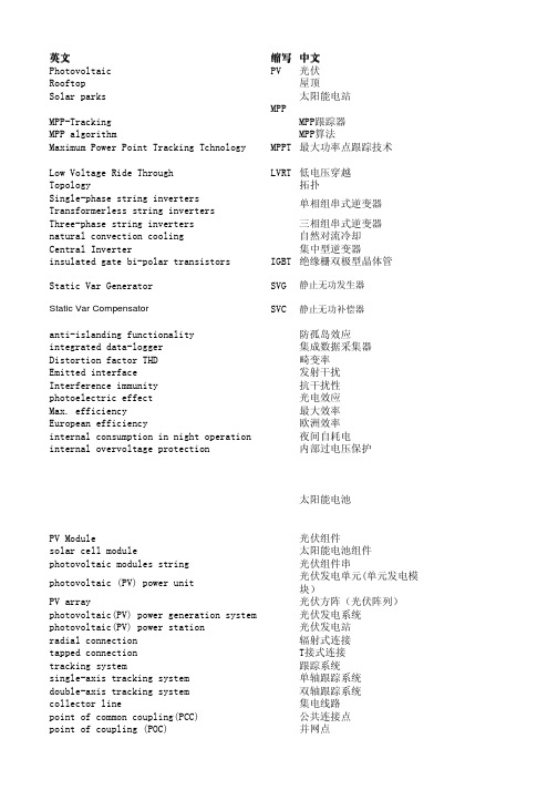
英文缩写中文Photovoltaic PV光伏Rooftop屋顶Solar parks 太阳能电站MPPMPP-Tracking MPP跟踪器MPP algorithm MPP算法Maximum Power Point Tracking Tchnology MPPT最大功率点跟踪技术Low Voltage Ride Through LVRT低电压穿越Topology拓扑Single-phase string invertersTransformerless string invertersThree-phase string inverters三相组串式逆变器natural convection cooling自然对流冷却Central Inverter集中型逆变器insulated gate bi-polar transistors IGBT绝缘栅双极型晶体管Static Var Generator SVG静止无功发生器Static Var Compensator SVC静止无功补偿器anti-islanding functionality防孤岛效应integrated data-logger集成数据采集器Distortion factor THD畸变率Emitted interface发射干扰Interference immunity抗干扰性photoelectric effect光电效应Max. efficiency最大效率European efficiency欧洲效率internal consumption in night operation夜间自耗电internal overvoltage protection内部过电压保护太阳能电池PV Module光伏组件solar cell module太阳能电池组件photovoltaic modules string光伏组件串photovoltaic (PV) power unit 光伏发电单元(单元发电模块)PV array光伏方阵(光伏阵列)photovoltaic(PV) power generation system光伏发电系统photovoltaic(PV) power station光伏发电站radial connection辐射式连接tapped connection T接式连接tracking system跟踪系统single-axis tracking system单轴跟踪系统double-axis tracking system双轴跟踪系统collector line集电线路point of common coupling(PCC)公共连接点point of coupling (POC)并网点单相组串式逆变器islanding孤岛现象intentional islanding计划性孤岛现象unintentional islanding非计划性孤岛现象Anti-islanding防孤岛peak sunshine house峰值日照系数low voltage ride through低电压穿越annual peak sunshine hours of PV station光伏发电站年峰值日照系数direct normal irradiance(DNI)法向直接辐射照度capacity of installation安装容量watts peak峰瓦solar time真太阳时type of protection防护等级(IP)protocol协议infeed starting at 发电起始值备注SVG的基本原理就是将自换相桥式电路通过电抗器或者直接并联在电网上,适当地调节桥式电路交流侧输出电压的相位和幅值,或者直接控制其交流侧电流,就可以使该电路吸收或者发出满足要求的无功电流,实现动态无功补偿的太阳能电池是一种由于光生伏特效应而将太阳光能直接转化为电能的器件,是一个半导体光电二级管。
电力系统继电保护中英文对照表
电力系统继电保护中英文对照表七戒旅长WW2OO5 七2007-10-26 11:14131Auxiliary relay/intermediate relay中间继电器132Common-mode voltage共模电压133Impedance mismatch阻抗失配134Intermittent fillet weld间断角缝焊接135Loss of synchronism protection 失步爱护136Closing coil合闸线圈137Electro polarized relay 极化继电器138Power direction relay功率方向继电器139Direct-to-ground capacity对地电容140Shunt running潜动141Trip/opening跳闸142Trip switch跳闸开关143Receiver machine收信机144High-frequency direction finder 高频测向器145Capacity charge电容充电146time over-current时限过电流148Surge guard冲击防护149Oscillatory surge振荡冲击150Fail safe interlock五防装置151Differential motion差动152Capacitive current电容电流154 Time delay延时156Normal inverse反时限157Definite time定时限158Multi-zone relay分段限时继电器159Fail-safe unit五防161Unbalance current 不平稳电流162Blocking autorecloser 闭锁重合闸163Primary protection 主爱护164Tap分接头165YC (telemetering) 遥测167Fault clearing time 故障切除时刻168Critical clearing time 极限切除时刻169Switch station开关站170Traveling wave行波171Protection feature爱护特性172Fault phase selector 故障选线元件173Fault type故障类型174Inrush励磁涌流175Ratio restrain比率制动176Laplace and Fourier transforms 拉氏和傅利叶变换177Short circuit calculations 短路运算178Load flow calculations潮流运算179Oscillatory reactivity perturbation 振荡反应性扰动180Quasi-steady state准稳态181Automatic quasi-synchronization 自动准同步182Protective relaying equipment 继电爱护装置183AC directional overcurrent relay 交流方向过流继电器184AC reclosing relay交流重合闸继电器185Annunciator relay信号继电器188Carrier or pilot-wire receiver relay 载波或导引线同意继电器189Current-limiting relay限流继电器190Definite time relay定时限继电器192Lockout relay闭锁继电器;保持继电器:岀口继电器193Micro-processor based protective relay 微机继电爱护194Voltage -controlled overcurrent relay 电压操纵过电流继电器196Fault diagnosis故障诊断197Back-up protection 后备爱护198Overhead line架空线199High voltage line 高压线路200Underground cable埋地电缆201Circuit breaker断路器202Bnishless excitation 无刷励磁203Interlock闭锁204Trigger触发器205Winding-to-winding insulation 绕组间的绝缘206Porcelain insulator 瓷绝缘子207Tie line联络线208Leased line租用线路209Private line专用线路211Remote Terminal Unit 远程终端设备212Economic dispatch system经济调度系统213State estimation状态估量214Trip by local protection爱护跳闸215Close by local protection爱护合闸216Operational (internal) oven-oltage操作(内部)过电压217Sampling and holding采样保持218Synchronized sampling采样同步219Manipulation操作220Measuring/Metering unit测量元件221Locus of measured impedance测量阻抗轨迹222Differential mode interference差模干扰223Output (executive) organ岀口(执行)元件224Overcurrent relay with underv r oltage supervision 低电压起动的过电流爱护225Low impedance busbar protection低阻抗母线爱护帖七戒旅长WW2OO5 A 2007-10-26 11:15228 Half-cycle integral algorithm半周积分算法230Coordination of relay settings爱护的整定配合231Reach (setting) of protection爱护范畴(定值)232Coordination time inten al爱护配合时刻时期233Percentage differential relay比率差动继电器234Electromagnetic relay电磁型继电器236Instantaneous unden r oltage protection with current supervision 电流闭锁的电压速断爱护237Operating equation (criterion)动作方程(判据)238Operating characteristic动作特性239Harmonic restraining谐波制动241Segregated current differential protection分相电流差动爱护242Branch coefficient分支系数Power line carrier channel (PLC)髙频通道245High speed signal acquisition system 高速数字信号采集系统246Busbar protection with fixed circuit connection 固建联结式母线爱护247Fault recorder故障录波器248Fault phase selection故障选相249Optoelectronic coupler光电耦合器件251Compensating voltage补偿电压252Polarized voltage极化电压253Memory circuit经历回路254Unblocking signal解除闭锁信号255Power system splitting and reclosing 解列重合闸Connection with 90 degree90度接线257Insulation supervision device 绝缘监视258Inrush exciting current of transformer 励磁涌流259Two star connection scheme两相星形接线方式260Zero mode component of traveling wave 零模行波261Inverse phase sequence protection逆相序爱护262Offset impedance relay 偏移特性阻抗继电器263Frequency response频率响应264Activate the breaker trip coil起动断路器跳闸266Pennissive under reaching transfer trip scheme 欠范畴承诺跳闸式267Slight (severe) gas protection轻(重)瓦斯爱护268Man—machine interface人机对话接口270Three phase one shot reclosure 三相一次重合闸271Out-of-stcp失步272Accelerating protection for switching onto fault 重合于故障线路加速爱护动作275Abrupt signal analysis 突变信号分析276Out flowing current外汲电流277False tripping误动279Turn to turn faults inter turn faults匝间短路280Relay based on incremental quantity 增量(突变疑)继电器281Vacuum circuit breaker真空开关282Power swing (out of step) blocking 振荡(失步)闭锁284Successive approximation type A/D 逐次逼进式A/D285Infeed current助增电流286Self reset自动复归287Adaptive segregated directional current differential protection 自适应分相方向纵差爱护288Adaptive relay protection自适应继电爱护289Pilot protection纵联爱护291Angle of maximum sensitivity最大灵敏角292Out of service退出运行294Waveform波形295Outlet岀口296Electromechanical机电的297Magnitude of current电流幅值299Traveling wave signal 行波信号300Measurement signal测量信号301Traveling wave relay 行波继电器302Transmission line malfunction 输电线路专门运行303Subsystem子系统304Positive sequence impedance 正序阻抗305Negative sequence impedance 负序阻抗306Zero sequence impedance零序阻抗307Digital signal processor 数字信号处理器308Frequency sensing频率测量309Cable relay电缆继电器Under power protection 低功率爱护311Under voltage protection 低电压爱护312Transient analysis暂态分析313Voltage sensor电压传感器314Zero-sequence protection零序爱护315Zero sequence current transducer 零序电流互感器316Shunt旁路,并联317Series串联,级数318Parallel并联319Saturation饱和320Free-standing独立的,无需支撑物的Troidal环形的,曲而,螺旋管形322Bushing套管323Magnetizing 磁化324Dropout current回动电流325Reactor grounded neutral system 中性点电抗接地系统326Grounding apparatus接地装置327Dual bus双总线328Thyristor晶闸管329Spark gap 火花隙330Damping circuit 阻尼电路331Discharge 放电332Platform 平台Grading等级334Line trap线路陷波器335Field test实地试验337Off-position“断开”位置,“开路”位置338Power-angle功角339Power-angle curve 功角特性曲线340Torque-angle转矩角341Symmetrical components 对称重量342Constant常量,恒泄343Coupler耦合器345Concussion 震动Filter滤波器349Analogue 模拟350Insulator绝缘子351Switch cabinet 开关柜352Rated burdenMoad 额宦负载353Primary-次侧的354Remote-control apparatus 远距离操纵设备355Capacitance 电容356Capacitor电容器357Reactance 电抗358Inductor电感359Internal resistance 内阻Blow-out coil消弧线圈361Bundle-conductor spacer 分裂导线362Bundle factor分裂系数363Electromotive force 电动势364Volt-amphere characteristic 伏安特性365Outgoing line 引出线366electrolyte电解质368Load characteristic负载特性369Self-induction自感370Mutual-induction互感371Induction coefficient感应系数372Inductance couping电感耦合373Time-invariant时不变的回复3帖4帖七戒旅长**2005五2007"0・26 11:16374Terminal voltage端电压375Non-linear characteristics非线性特性376External characteristics外特性378Harmonic current正弦电流379Pole-pairs极对数380Quadrature正交381Angular velocity 角频率382Magnetic induction磁感应强度385Armature电枢386Peak value(交变虽的)最大值387A mutually induced um.f 互感电动势388The applied voltage 外施电压389Zero-power-factor 零功率因数390The no-load power factor 空载功率因数391Sinusoidal variations正弦变疑392A lagging power factor 滞后的功率因数393Equivalent circuit等值电路394Capacitance effect 电容效应395Direct axis 直轴396Quadrature axis 交轴398 Concentrated coil 集中绕组399Magnetization curve 磁化曲线400Residual magnetism 剩磁401Rated armature current额定电枢电流402Series excited 串励403Self excited 自励404Shunt excited 并励405spottily excited 他励407Electromagnetic torque 电磁转矩408a retarding torque 制动转矩409Rectangular wave 矩形波410Synchronous speed 同步转速411Electromagnetic brake 电磁制动412synchronous reactance 同步电抗413synchronous condenser 同步调相机414Load shedding 甩负荷415Black-start黑启动417Distribution feeder 配电馈线418Commissioning投运419Reactive power compensation 无功补偿器420Continuous rating连续运行的额左值421Al (artificial intelligence) 人工智能422Network topology网络拓补424Configuration control组态操纵425Topological information拓补信息426Black-out area停电区自适应继电爱护429Adaptive features自适应特性430Phase comparison relays相位比较继电器431Directional contact方向触点432Protective gap 爱护间隙433Protective earthing爱护接地434Protective earthing; outer insulation 爱护绝缘435Protection switch爱护开关436Protective cap爱护帽437Protective panel 爱护屏柜439Protection device爱护设备爱护外壳441Catch net; protecting net 爱护网442Protection system 爱护系统443Protective link爱护线路444Protective ground 爱护性接地445Protective cover; Protective housing 爱护罩446Protection device: Protective gear 爱护装置447Protective transformer 爱护变压器448Alarm relay报警信号继电器449Alarm signal: alerting signal 报警信号450Admittance relays 导纳型继电爱护装置451Low-voltage protection低压爱护Under-voltage release 低电压跳闸453Under-voltage trip 低电压自动跳闸454Under-run低负荷运行455Under-power protection 低功率爱护456Under-power relay 低功率继电器457Under-frequency protection低频爱护458Low-frequency high-voltage test 低频髙压实验459Low-voltage relay低压继电器460Low-voltage release relay 低压开释继电器461Under-frequency protection 低周波爱护463Under-impedance relay 低阻抗继电器465Conductance relay电导继电器466电动机磁场故障继电器467Dynamoelectric relay电动式继电器468Electric reset relay 电复位继电器469Power-transformer relay 电力传输继电器471Power system oscillation 电力系统振荡472Electric interlock relay 连锁继电器473Current overload电流过载474Self-polarizing relay电流极化继电器475Current-balance relay 电流平稳式继电器476Circuit control relay电路操纵继电器479Capacitance relay 电容继电器480Capacity ground电容接地Voltage balance relay 电压平稳继电器482Circuit control relay电路操纵继电器483Voltage responsive relay 电压响应继电器484Voltage selection relay 电压选择继电器485Power failure电源故障486Power-transfer relay电源切换继电器487vacuum-tube relay电子管继电器488Ohm relay电阻继电器489Timing relay; timed relay 定时继电器490Time pulse relay定时脉冲继电器492Directional over-current relay 方向过流继电器493Directional over-current protection 方向过流爱护494Directional distance relay 方向距离继电器495Directional pilot relaying 方向纵联继电爱护497Cut-off relay断路继电器498Circuit breaker failure protection 断路器故障爱护装置500Open-phase relay断相继电器501Earth-leakage protection 对地漏电爱护502Multiple-reclosing breaker 多次重合闸断路器503Multi-ended circuit protection 多端线路爱护506Multiple earth多重接地507Two-position relay 二位宜继电器508Generator protection 发电机爱护509Generator cutout relay发电机断路继电器Generator protection for negative sequence current 发电机负序电流爱护511Transmitting relay发送继电器512Back-spin timer反转时刻继电器513Auxiliary relay辅助继电器514Negative phase relay负相位继电器515Negative-phase sequence impendence负相序继电器516Underload relay负载不足继电器517Back-up over-speed governor 附加超速爱护装置518Induction cup relay感应杯式继电器520Induction type relay感应式继电器521Induction disc relay感应圆盘式继电器522High sensitive relay 高灵敏度继电器回复4帖5 帖七戒旅长WW2OO5 四2007-10-26 11:16523High-speed impedance relay 髙速阻抗继电器524High-voltage relay 髙压继电器525Power relay 功率继电器527Transition impedance 过渡阻抗528Thermal protection过热爱护529Temperature limiting relay 过热继电器530Overload relay 过载继电器531Overload trip过载跳闸532Thermostat relay 恒温继电器533Closing relay 合闸继电器Transverse differential protection 横差爱护535Transfer of auxiliary supply 后备电源切换536Back-up system 后备继电爱护537Delay-action relay 缓动继电器538Slow-to release relay 缓放继电器539Converter relay换流器继电器540Electromechanical relay 机电继电器541Biased differential relaying 极化差动继电爱护系统542Discontinuous relay 鉴别继电器543Transistor relay 晶体管继电器544Crystal can relay 晶体密闭继电器545Static relay 静电继电器546Fast-operate slow-release relay 快动缓释继电器547Fast-release relay 快开释继电器549Excitation-loss relay 失磁继电器553Two-phase short circuit fault 两相短路故障554Two-phase grounding fault 两相接地短路故障556Sensitive polarized relay 灵敏极化继电器558Sensitive relay 灵敏继电器560Abnormal overload 专门过载561Abnormal overvoltage 事故过电压562Above earth potential 对地电势563Absolute potential绝对电势564AC circuit breaker交流断路器565AC component交流重量566AC distribution system 交流配电系统Air-blast circuit breaker空气火弧断路器568Air-blast switch空气吹弧开关569Air brake switch空气制动开关571Air breaker空气断路器572Air-space cable空气绝缘电缆573Alive带电的574All-relay interlocking 全部继电连锁575All-relay selector 全继电式选择器578Arc extinguishing coil灭弧线圈579Arc suppressing reactor 灭弧电抗器580Asymmetric load不对称负载Asymmetric short circuit 不对称短路582Asynchronous reactance 异步电抗583Asynchronous resistance 异步电阻584Biased differential relaying 极化差动继电爱护系统585Bi-directional relay双向继电器586Blinker继电器吊牌587Blocking relay连锁继电器589Blowout coil 灭弧线圈590Bus hub总线插座591Bus protective relay 母线爱护继电器592Bus section breaker 母线分段断路器593Bus terminal fault 母线终端故障594Bus separation 母线分离595Bus tie circuit breaker母线联络继电器596Bypass 旁路597Coil factor线圈系数598Compound relay 复合电路599Continuous load连续负载600Counting relay 计数继电器602Cut-off of supply 停止供电603Cut-out relay 短路继电器604Dash current冲击电流605Data medium数据载体606Data processing 数据处理607Data transmission 数据传输608Emergency service 事故运行609Emergency standby 事故备用611Extinction coil消弧线圈612Extinguishing voltage 消弧线圈613Extra high voltage 超高压614Fault line故障线615Fault location故障左位616Feedback 反馈617Feeder馈电线618Interlock连锁619Intermittent fault间歇故障620Interrupting time 断路时刻621Negative direction 反方向622No-load release 无跳闸623Off-peak非峰值的624Operating load运行负载625Orthogonal正交的626Rated primary voltage 一次额泄电压627Rated secondar}- volage 二次额定电压628Remote controlled 遥控的629Reserve bus备用母线630Rotor转子631Sectionalizer分段断路器632Self-energizing自激的633Sequential tripping 顺序跳闸637Surge voltage冲击电压638Sustained overload 连续过电压639Symmetrical 对称的640Fault component 故障重量641Wavelet transform 小波变换642Object-oriented 而向对象643Faults recorder故障录波644Setting calculation 整立运算645Topology analysis 拓扑分析646Expert system 专家系统647Security安全性651Load schedule according to frequency change 按周波减载653Semiconductor, semiconductor diode, transistor 半导体、半导体二级管、三极管654Semi-orthogonal wavelet半正交小波656Saturation, saturation detection, saturation curve饱和,饱和检测,饱和曲线657Relay location爱护安装处658Coordination of relay settings爱护的整定配合659Coordination time interval爱护配合时刻时期660Relay system configuration爱护配置661Redundancy of relaying system爱护配置的冗余度663Protection devices, protection equipment爱护装垃ora 93UEp9dlUI 9ojns 'auepadlU!9厶9ZJ:H 9701P00乙三900乙••讲埶砒T刊9WV>0UOIJBOIJIJUOpi UIJOJOAEM"9心!30[6\ UOIlBoEdojd 9ABMH9P9JJ0 Sp^OOJ£厶9网萊劇琳3dXi)〕n 阳ZL9XIJ1PIU UOIIBUIJOJSUP.I10厶9廉园卷封a uoipunjSuiiduiES g899再wsrw mouoduioouoijBiuixojddv999乐甜UUEIV£99 坠审回虫时訣甲修鲁朋幕蒸出蛊ooiAop uoijjojojd jojuojjno oununpj puu mojjno OUIJJEISt99 677Compensation voltage补偿电压678Compensation theorem compensation principle 补偿原理679Unavailability, failure rate不可用率,失效率680Immune to electromagnetic interference 不受电磁干扰681Abnormal operating condition不正常运行状态682Sampling interruption service program 采样中断服务程序683Synchronizing by reference parameter vector 参数矢量同步法684Operational(internal) over voltage 操作(内部)过电压685Manipulating organ操作单元686Measurement, measuring unit 测量,测疑单元687Measured impedance测量阻抗688Locus of measured impedance 测量阻抗轨迹689Differential relay差动继电器690Differential mode interference差模干扰691Distributed capacitance of long line 长线分布电容692Normally closed contacts 常闭节点693Normally open contacts 常开节点694Over reach blocking scheme 超范畴闭锁式696Extra-high-voltage transmission line 超高压传输697Sustained faults连续性故障698Output(executive) organ出口(执行)元件699Contact触点、接点700Capacitor of series compensation串补电容701Window function窗函数702Differential relay with fast saturated current transformer 带有速饱和变流器的差动继电器703Single-chip microcontroller单片机704Single-phase(three phase) transmission line 单相(三相)传输线705Unit protection单元式爱护707Low frequency component, subharmonic低频重量,低次谐波708Low impedance bus bar protection低阻抗母线爱护709Current traveling wave电流行波710Electrical apparatus, equipments电器设备711Electrical network・ power network电网712Voltage waveform distortion 电压波形崎变713Voltage traveling wave电压行波714Operating time动作时刻715Multiphase compensated impedance relay 多相补偿式阻抗继电器716Generator, generator-transformer set 发电机,发电机一变压器组717Protection of generator-transformer set 发电机一一变压器爱护718Field failure protection of generator发电机的失磁爱护720Metallic fault金属性故障721Transistor type relay晶体管型继电器723Differential protection with percentage restraining 具有比率制动的差动继电器724Pilot protection using distance relay距离纵联爱护726Stator ground protection based on zero sequence current 零序电流构成的定子接地爱护728Zero sequence ct零序电流互感器729Zero sequence current relay零序电流继电器730Mutual induction of zero sequence零序互感的阻碍731Bus bar protection母线爱护732Combined bus and transformer protection母线和变压器共用爱护733Energy directional relay能量方向继电器734Inverse power protection逆功率爱护735Inverse phase sequence protection逆相序爱护736Frequency window频窗737Frequency component频率重量738Slight gas protection, severe gas protection 轻瓦斯与重瓦斯爱护739Man-machine interface人机对话接口740Weak power end protection弱电源端爱护741Three terminal line protection三端输电线爱护742Digital protection数字式爱护743Digital signal processor(dsp)数字信号处理744Double bus bar protection双母线爱护745Ultra-high voltage transmission特高压输电746Trip relay跳闸继电器747Communication interface通讯接口748Communication channel通讯通道749Mutually coupled lines有互感线路750Relay based on transient component 暂态爱护751Relay based on incremental quantity 增屋继电器753Heavy load重负荷754Relay acceleration after auto-reclosing 重合闸后加速爱护755Relay acceleration before auto-reclosing 重合闸前加速爱护756Main protection主爱护757Automatic reclosure自动重合闸758Adaptive relay protection自适应继电爱护762Longitudinal differential relay纵联差动继电器763Impedance converter阻抗变换器764Impedance circle 阻抗圆765Angle of maximum sensitivity 最大灵敏角766Minimum load impedance 最小负荷阻抗767Blocking signal闭锁信号768Arcing fault电弧接地故障769Isolated neutral system 中性点绝缘系统770Arc suppression coil消弧线圈771Healthy phases非故障相772Remote terminal unit(RTU) 远方终端773Power line carrier(PLC)电力线载波774Parallel port并行出口775Serial port串行接口776Clock时钟777SCADA监控与数据采集778Scan扫描779Self-check自检780Alarm告警781Pulse脉冲782Ground-fault of ungrounded systems 小电流接地系统785Load patterns负荷形式788Voltage instability电压不稳789Fast response 快速响应790Dynamic attributes 动态特性791Telemeter data遥测数据792Abnormal state专门态793Reverse power flows 功率逆潮流796Phase comparison relays 相位比较继电器798Switching surge开关冲击799Cascading outages连锁故障800Adaptive relaying自适应继电爱护801Time interval时刻间隔802Voltage dip电压下降803。
无功补偿毕业设计外文翻译
文献翻译英文原文:Issues for reactive power and voltage control pricing in aderegulated environmentAbstractIssues related to reactive power, voltage support and transmission losses as dictated from a certain class of electric loads are addressed. Specifically, the impact of predominantly induction motor loads on voltage support, reactive power requirements, and transmission losses is examined. These issues are examined with a model, which explicitly models the induction motor mechanical load. Simulation results on a simplified electric power system are presented. Based on these results, a pricing structure for voltage and reactive power support is proposed. The basic assumption of the paper is that, in a deregulated environment, the expense of the incremental requirements for voltage control should be charged to the member causing the additional requirements. The results of this work can also be used to justify long-term pricing agreements between suppliers and customers.Keywords: Reactive power; Induction motor loads; Voltage support; Reactive power pricing1. IntroductionVoltage control in an electric power system is important for many reasons: _a.all end-use equipmentneed near-nominal voltage for their proper operation, _b. near-nominal voltageresults in near-minimum transmission losses, and _c. near-nominal voltages increase the ability of the system to with-stand disturbances _security.. A reasonable voltage profile throughout an electric power system is associated with the ability of the system to transferpower from one location to another. When the voltage sags to low values, this ability of the system is compromised. The onset of power transfer inability canbe detected with sensitivity analysis of reactive power requirements vs. real power load increases. This sensitivity is dependent on the characteristics of the electric load. Such sensitivity analyses have been performed using various electric load models, i.e. constant power load, constant impedance load, or combination of the two _voltage-dependent load. The majority of electric loadsare induction motors. These loads do not fit into any of the load model categories mentioned. Yet, they drastically affect the stability of the electric power system. In this paper, we assert the need to model induction motor loads within the power flow formulation and directly evaluate the effects of such loads on reactive power requirements. It is shown that the power flow formulation can be augmented to include the specific induction motor loads. Interesting nonlinear phenomena occur when the voltage at induction motor loads sags to low values. These phenomena affect the performance of the transmission system. In a deregulated environment, it makes sense to examine these phenomena and design a pricing model based on the economicimpact of these phenomena. The paper is organized as follows: first, a formulation is proposed, which explicitly models the induction motors. This formulation is introduced as an extension to the usual power flow problem.Then, a sensitivity analysis procedure is introduced. This sensitivity is basedon an extension of the co-state method. The proposed methods are applied toa simplified system comprising induction motor loads. The results of this system are discussed. A pricing approach for voltage support and reactive power requirements is presented.4. Example resultsThe application of the model presented in this paper is demonstrated on a simple electric power system, consisting of a generating substation, step-up transformer, a transmission line, step-down transformerand several induction motors. The system is illustrated in Fig. 2. Theparameters of the system have been selected to represent typical systems and they are shown in Table 1. It is important to realize that the motors may or maynot be controlled by variable voltage-variable frequency drives. For this system,we performed parametric studies of the voltage level, the reactive power requirement, and the transmission losses. The variable parameter is the total induction motor load. This parameter is denotedwith the variable y in Table 1. Also note that the model requires the mechanical load torque, T m . Theassumed mechanical torque is listed in Table 1.Fig. 3 illustrates the variation of the voltage magnitude and the generating unit reactive power outputas the total induction motor load increases. Note that, when the induction motor load increases beyond the value of 0.90 p.u., the reactive power requirement increase and the voltage magnitude decreases below 0.9 p.u. When the load increases beyond the value of 1.2 p.u., the voltage collapses.What happens in this case is that the induction motor moves to an operatingpoint of very high slip, in this case, ss0.27, absorbs higher reactive power and causes the termi-nal voltage to dip _voltage collapse.. Note that the voltage collapse is abrupt and unexpected. It is important to observe that this behaviorof the proposed Fig. 4. model is realistic and quite different from simplified models such as constant power or constant impedance load models.The performance of the system in the presence of induction motor loads canbe better understood by studying the sensitivity of voltage magnitude, reactive power requirements and transmission losses vs. induction motor load. Figs. 4–6 illustrate these sensitivities as functions of total induction motor rated load.In Fig. 4, it is apparent that the sensitivity of the voltage magnitude becomesvery high as the electric motor load approaches 1.2 p.u. It would be expedientto impose operating limits using the sensitivity of voltage magnitude. For example, if one is to apply limits to this sensitivity, i.e. 20%, then it is apparentthat for this system, the induction motor load should not be more than 0.8 p.u.of the system rated power. Similarly, one can observe in Figs. 5 and 6 that thesensitivity of reactive power requirements and transmission losses increase drastically as the induction motor load increases. It is important to note that when the induction motor load is 0.8 p.u., the sensitivity of reactive power torated load is 1.0, i.e. any additional 1 MW of load will require 1 MVA of generated reactive power. When the induction motor load becomes 1.0 p.u.,the sensitivity becomes 1.58 MVA /MW. Similarly, the transmission loss sensitivity with respect to load increases drastically as the induction motor load reaches 1.0 p.u. For example, when the load is 1.0 p.u., the incremental losses become 4%, a relatively high value.Figs. 4 –6 illustrate that at the point before the voltage collapse, the sensitivities become very high. Specifically, the voltage sensitivity is y1.0, the reactive power sensitivity is 3.8 MVA rMW and the transmission loss sensitivity is 0.094. This data can be used in two ways. First, application of limits onsystem sensitivities will ensure that the system never operates near the pointof voltage collapse. Second, the sensitivities can provide the basis for settingtariffs for voltage support and reactive power of predominantly induction motor loads. The basis of the tariff structure and its implementation is discussed in Section 5. One can argue that these tariffs may be applied to all loads for simplicity.The results in Figs. 3–6 were obtained for a specific system. The same information can be obtained for any system using the proposed model. Thenthis information can be utilized to impose tariffs for loads that arepredominantly induction motors.5. Tariff structureThe basis of the tariff structure is the cost of providing v oltage and reactive power support subject to acceptable system performance. Acceptable system performance can be established by imposing limits to the sensitivities of voltage magnitude and reactive power requirements. These limits are system dependent and should be decided upon extensive studies of the system. Thesame studies will providethe range of sensitivities of voltage magnitude, reactive power requirements and transmission losses. Adirect cost can be associated with the transmission losses. An investment costcan also be associatedwith reactive power requirements. Let x be the average transmission loss sensitivity and z be the maximum reactive power sensitivity. Then the cost of providing these services is:C=p1 x+p2 z ,where p1 is the price of electric energy, and p2 is the investment cost of reactive power sources.Note that the investment cost must be computed on the basis of the maximum requirements throughoutthe study period. The cost C provides the basis for establishing the actual tariffs. It is also important to note that, today, technology exists to monitor theimpact of a specific load on the system resources. Using this technology, onecan monitor the voltage magnitude, reactive power and most importantly the sensitivities of voltage magnitude, reactive power requirements, and transmission losses. It is conceivable that pricing can be performed in real timeon a use-of-resources basis.6. Summary and conclusionsThis paper has addressed the impact of predominantly induction motor loadson voltage magnitudes, reactive power requirements, and transmission losses.A model has been proposed to evaluate this impact on large-scale power systems. The proposed model incorporates the physical model of induction motors into the power flow formulation. As such, it is a realistic model and captures the true behavior of these loads.Example calculations were carried out on a simplified power system. For this system, the voltage level, the active and reactive power requirements, and the transmission losses were computed vs. the total induction motor load. The model provides sensitivities of these quantities with respect to the inductionmotor loads and can be used to predict the total amount of load, which can be supported by the system _voltage stability limit..It was shown that there is a critical value of the load and when the load increased beyond this value,the reactive power requirements and the transmission losses increase in a highly nonlinear fashion. Theonset of this condition is system dependent and can be determined with a series of simulations. A practical approach w ill be to use probabilistic simulation techniques, similar to those described in Ref., to obtain a statistical distribution of the critical induction motor loads.The results provide the basis for deriving aggregate electric load models andthe designing of a pricing schedule for voltage support and reactive power requirements. Specifically, the pricing is based on the cost function of the actual incremental losses and the cost of reactive power source requirements. Incremental loss cost is computed from the price of electric energy. The cost of reactive power sources is computed from the maximum required reactive power over a specified period of operation.译文:在解除管制的环境下功率和电压控制的定价问题摘要对由于处理某一类电负载而引起的功率、电压、传输损耗的相关问题的研究。
无功补偿常用计算公式及应用实例

解:每台电容器额定电流 I`N =331011103200⨯⨯⨯=31.45A 每相电容器额定电流 I N =3⨯31.45=94.35A 每相容抗 X C =335.9410113⨯⨯=67.4Ω每相感抗 X L =67.4⨯6%=4.04Ω X L =2πFL L=f XL π2=31404.4=0.0128H =12.8mH(4)已知一台三相电容器,规格为30kvar/450v,要求按6%电抗率选配电抗器A. 电容器额定工作状态下的计算— 每相额电流I=450310303⨯⨯=38.49A, 每相等值容抗c X =49.383450⨯=6.75ΩB. 电抗器选择—X L =0.06⨯6.75=0.405Ω Q L =3(249.38⨯0.405)=1.8kvarC. 电源电压为380v,不设电抗器时的计算— 每相工作电流I=A 5.3275.63380=⨯电容器输出功率c Q =3⨯32.5⨯380=21.39kvar D. 电源电压为380v,设上述电抗器时的计算每相工作电流'I =)X -(X 3l c ⨯U=)405.075.6(3380-⨯=34.545A电容器端线电压'U =3('I ⨯c X )=3(34.545⨯6.75)=403.86V电抗器压降L U ='I ⨯L X =34.545⨯0.405=14V 电抗器总功率'L Q =3('I ⨯L U )=3(34.545⨯14)=1.451Kvar 电容器总功率'c Q =3('I ⨯'U )=3(34.545⨯403.86)=24.163Kvar电抗器功率与电容器功率之比值%6163.24451.1''L ==c Q QE. 通过上例计算得出以下结论— a.接入电抗器后,能使电容器端电压提高, 从而在相同电源电压条件下,能提高电容 器的输出功率;b.电抗率之比同等于二者全功率之比;c.增设电抗器后,由于电路中容抗的减少,从而提高输出电流。
无功补偿节电效果简要计算分析
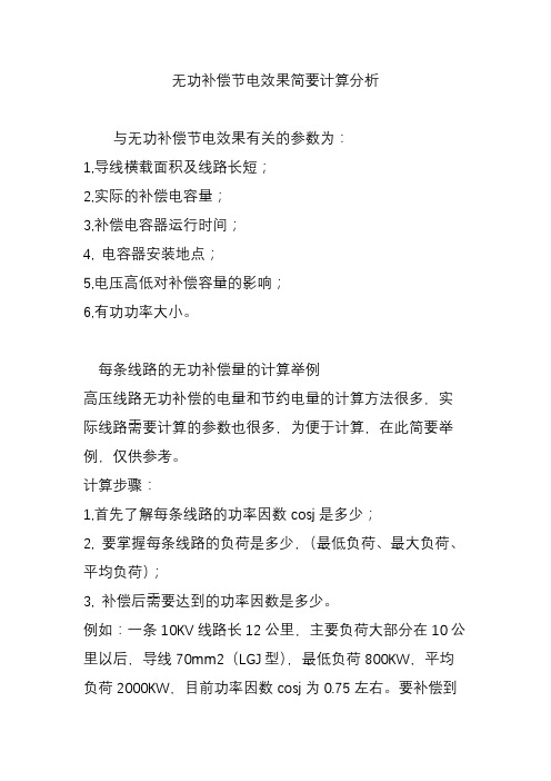
无功补偿节电效果简要计算分析与无功补偿节电效果有关的参数为:1,导线横载面积及线路长短;2,实际的补偿电容量;3,补偿电容器运行时间;4, 电容器安装地点;5,电压高低对补偿容量的影响;6,有功功率大小。
每条线路的无功补偿量的计算举例高压线路无功补偿的电量和节约电量的计算方法很多,实际线路需要计算的参数也很多,为便于计算,在此简要举例,仅供参考。
计算步骤:1,首先了解每条线路的功率因数cosj是多少;2, 要掌握每条线路的负荷是多少,(最低负荷、最大负荷、平均负荷);3, 补偿后需要达到的功率因数是多少。
例如:一条10KV线路长12公里,主要负荷大部分在10公里以后,导线70mm2(LGJ型),最低负荷800KW,平均负荷2000KW,目前功率因数cosj为0.75左右。
要补偿到0.95,需补偿电容器多少千乏?根据该线路情况,每千瓦的无功补偿量不低于平均负荷2000KW。
(查附表3,另见:《电容补偿表》。
补偿前0.75,要补偿到0.95,每千瓦要补偿电容量0.55千乏)。
即:2000×0.55=1100千乏(总补偿量)最低负荷为800KW即:800×0.55=440千乏,约450千乏根据该线路负荷,一组采用固定补偿450千乏左右,另一组采用自动投切补偿650千乏左右,总无功补偿量1100千乏左右,这样可使功率因数平均保持在0.95左右。
有关功率因数大小的当前数值未知时,可按月供有功电量和无功电量计算,查附表4所得,平均负荷量多少千瓦,按月有功电量除以运行时间,就可以得出平均负荷。
1.1.2 安装地点及节约电量降低损耗的计算方法。
安装地点:上述线路负荷大部分在10公里以后,固定的450千乏电容器组可安装在负荷集中处,自动补偿的650千乏安装在负荷集中的上侧,补偿原则可达到就地就近平衡。
节约电量:该线路为70mm2导线,查附表2,每公里电阻0.46Ω,按10公里总电阻为4.6Ω。
节电的方法英语作文

节电的方法英语作文英文回答:There are numerous ways to conserve energy, both in our homes and in our businesses. Some simple steps can make a big difference, such as turning off lights when leaving a room, unplugging appliances when not in use, and using energy-efficient appliances.Adjust the thermostat: Turning down the thermostat by just 1 degree in winter or turning it up by 1 degree in summer can save up to 10% on your energy bill.Use energy-efficient light bulbs: LED bulbs use up to 80% less energy than traditional incandescent bulbs, and they last for much longer.Unplug electronics when not in use: Even when electronics are turned off, they can still draw power from the outlet. Unplugging them when not in use can save youenergy.Use a power strip: Power strips make it easy to turnoff multiple devices at once. This can save energy and prevent power surges.Install a programmable thermostat: Programmable thermostats allow you to set different temperatures for different times of the day. This can help you save energyby reducing the temperature when you are not home or asleep.Get a home energy audit: Home energy audits can help you identify areas where your home is losing energy. Once you know where the problems are, you can take steps to fix them and save money.By taking these simple steps, you can make a big difference in your energy consumption and save money onyour energy bills.中文回答:我们可以通过多种方式节省能源,无论是在家中还是在公司里。
- 1、下载文档前请自行甄别文档内容的完整性,平台不提供额外的编辑、内容补充、找答案等附加服务。
- 2、"仅部分预览"的文档,不可在线预览部分如存在完整性等问题,可反馈申请退款(可完整预览的文档不适用该条件!)。
- 3、如文档侵犯您的权益,请联系客服反馈,我们会尽快为您处理(人工客服工作时间:9:00-18:30)。
Plans for saving electricity节电方案计划Today's companies face a wide range of competition, and constantly reduce the power consumption is not only an important way to reduce costs to improve competitiveness over a long period of time, and is the realization of their own is the effective means to make contributions to reduce emissions当今企业面临广泛的竞争,不断降低电力能耗不仅是长期降低成本提高竞争力的重要途径,而且是实现自身为降低排放作贡献的有效手段。
The way of energy saving of enterprises企业电力节能的途径First, because of the power efficiency of the electric power sector, the improvement of power factor can make no work penalty.一是由于电力部门考核的电力效能,即功率因素提高方面,可使无功罚款转变为无功奖励。
Second,The energy saving effect can be about 8 ~ 15% of the compensation of the load on the side of the load二是自身负载侧的无功修正及线损补偿,其节能效果可以达到8~15%左右。
Third,Electric power special aspects: such as load management, may reduce power load peak power 5 ~ 30%, for a lot of electricity companies such as steel mills, a year can save electricity cost millions三是电力能源的特殊方面:比如负荷管理,可能使电力负荷高峰功率降低5~30%,对一个大量用电企业如钢厂,每年可节约用电费用几百万之巨!Fourth,Clean energy saving on electricity, with a focus on the possible power grid harmonic filter, on the basis of conventional energy saving effect, improve skills 3 ~ 50%, especially can improve the reliability of the system四是着力于电力清洁节能,重点是滤除可能存在的电网谐波,可在常规节能效果的基础上,提高技能率3~50%,特别是可以提高系统的可靠性。
Fifth,Comprehensive energy management, comprehensive, scientific and efficient management of electricity, water and gas can increase comprehensive energy efficiency to about 10-20%五是综合性的能源管理,对电、水、气等实行综合、科学、高效的管理,可将综合能源利用率提高到10~20%左右。
The enterprise is reactive power and harm企业无功功率及危害The reverse of the magnetic field generated by the current hysteresis of a transformer,motor, induction heater, coil, etc. Is called reactive power. Moreover, the transmission of electricity also produces a lot of reactive power. They lead to:电网中的变压器、电机、感应加热器、线圈等感性负载的电流滞后产生的磁场反向能称为无功功率。
此外电力的输送也会产生大量的无功功率。
他们导致:Companies have low corporate factors and fines企业企业因数低而罚款Increased power consumption and electricity costs增加电能消耗及用电成本Increase the power loss of power grid and drop the power grid增大电网功率损耗及电网压降Reducing transmission efficiency降低输电效率Increase transformer loss and distribution cable size增加变压器损耗及配电电缆尺寸Cause transient, transient, fluctuation, distortion, lower concave, etc引发瞬变,暂态,波动,畸变,下凹等The power factor of the various load of the enterprise企业各种负载的功率因数Load categories 负载类别Male child ~ full半载~满载Induction motor 感应电机 0.6~0.9The general industry 一般工业 0.6~0.8The paper industry 造纸工业 0.5~0.8Chemical equipment 化工设备 0.75~0.85Arc furnace电弧炉 0.6~0.8The cement industry 水泥工业 0.75~0.85Ac welding machine 交流焊机 0.35~0.4The steel industry 钢铁工业 0.6~0.85The plastics industry 塑胶工业 0.6~0.75Enterprises improve the economy of power factors企业提高功率因数的经济性●Reduce the total current of the system降低系统总电流总有功无功●Reduce the loss of transformer and transmission lines降低变压器及输电线路损失P=3*I2*RReduction of I reduces the loss power PI减少使损失功率P相应减少●Increase the utilization of transformer and line增加变压器及线路的利用率●Stabilize and improve system voltage稳定及提高系统电压●The payback period is between 6 and 24 months投资回收期在6-24个月之间●To meet the development concept of environmental protection (saving 1 degree of electricity and reducing carbon dioxide emissions by 0.997 kg)符合节约环保的发展理念(节约1度电可减排0.997kg二氧化碳)Here are the examples of the storaenso factory:针对斯道拉恩索工厂计算示例如下:Reactive power compensation capacity fast query table■无功功率补偿容量快速查询表Compensation capacity query and calculation补偿容量查询与计算Qc=Pw×FQc:The amount of reactive capacity that needs to be compensated需补偿的无功容量Pw:The system has the power of power系统有功功率F:The coefficient in the query table查询表中系数Cos Φ before 1 by compensation and compensation of cosine Φ 2 queries由补偿前的cosΦ1及补偿后的cosΦ2查询得出。
一、800AE03●3.5 MVA transformer3.5MVA的变压器●35/0.72 kv transformer35/0.72kv变压器●The actual current average of 1600A实际电流平均值1600A●The average power factor is 0.8原功率因数平均值为0.8●The target power factor 0.96目标功率因数0.96To calculate:Cos Φ 1 = 0.8, cos Φ 2 = 0.96, U = 0.69 KVPw=*U*I* cosΦ, thePw=From 0.8 to 0.96, the coefficient is F = 0.458The amount of reactive capacity that needs to be compensated for is Pw x F = 1835* 0.458 = 840KvarWhen the voltage is 690V, the rated voltage is 815V, and the resistance rate is 7%The installed capacity of the reduced capacity is approximately 1089KvarCompensation before: the total currentI总1===1919A,Power consumption P1=U*I总1=0.69*1919=1324 Kw·h After the compensation: total currentI总2===1599A,Power consumption P2=U*I总2=0.69*1599=1103 Kw·hI差= I总1- I总2=1919-1599=320ASaving electricity per hourP差= P1 - P2 = 1324-1103 = 221Kw/hThe annual cost of saving the electric bill is the same as the P差* 24 * 365 * 0.52 = 1006699.2 yuan计算:cosΦ1=0.8,cosΦ2=0.96,U=0.69KVPw=*U*I* cosΦ,则Pw=*0.69*1600*0.96=1835Kw则由0.8至0.96从上表中查出系数为F=0.458则需补偿的无功容量Qc= Pw×F =1835*0.458=840Kvar而当系统电压为690V,采用额定电压为815V,电抗率为7%时,需要考虑降容那么降容后的安装容量Qn约为1089Kvar补偿前:总电流I总1===1919A,耗电P1=U*I总1=0.69*1919=1324 Kw·hθ==1599A,耗电P2=U*I总2=0.69*1599=1103 Kw·h 补偿后:总电流I总2=θI差= I总1- I总2=1919-1599=320A每小时节电:P差=P1 -P2=1324-1103=221Kw·h每年节约电费P差*24*365*0.52=1006699.2元The compensation plan is as follows:System voltage 690 v, rated voltage 815 v, the reactance rate was 7%, the actual installation capacity of 794 kvar (by 800 kvar to compensation), points to two cabinet, 400 kvar respectively, single tank points 9 loop, 25 kvar * 2 + 50 kvar *7, the configuration list as follows:补偿方案如下:系统电压690V,采用额定电压815V,电抗率为7%,则实际安装容量1089kvar(按1100kvar 来补偿),分两个柜子,分别为550kvar,单柜分12个回路,25kvar*2+50kvar*10,配置清Rated current compensation I===779A, draw out the switch capacity to choose 5 to 7 times the rated current, size in 3895A(or two 1947A separate control cabinet) above!Summary: (800AE03)1、The installed reactive capacity is 1100kvar2、The current is reduced by 320A after the reactive power compensation cabinet is installed3、The cost of saving energy is 1006699.2yuan ($0.52) per year after installing the reactive tank.补偿柜额定电流I===779A,抽屉式开关容量选择额定电流的5-7倍来计算,大小在3895A(或者2个1947A分别控制2个柜子)以上!总结:(800AE03区域)1、安装无功补偿容量为1100kvar2、安装无功补偿柜之后,电流减少了320A3、安装无功补偿柜后,每年节约电费是1006699.2元(电费每度0.52元)二、800AE04●3.5 MVA transformer3.5MVA的变压器●35/0.72 kv transformer35/0.72kv变压器●The actual current average of 1400A实际电流平均值1400A●The average power factor is 0.7原功率因数平均值为0.7●The target power factor 0.96目标功率因数0.96To calculate:Cos Φ 1 = 0.7, cos Φ 2 = 0.96, U = 0.69 KVPw=*U*I* cosΦ, the Pw=From 0.7 to 0.96, the coefficient is F = 0.729The amount of reactive capacity that needs to be compensated for is Qc= Pw×F =1606*0.729=1170KvarWhen the voltage is 690V, the rated voltage is 815V, and the resistance rate is 7%The installed capacity of the reduced capacity is approximately 1518KvarCompensation before: the total currentI总1===1919A,Power consumption P1=U*I总1=0.69*1919=1324 Kw·h After the compensation: total currentI总2===1399A,Power consumption电P2=U*I总2=0.69*1399=965 Kw·hI差= I总1- I总2=1919-1396=523ASaving electricity per hourP差=P1 -P2=1324-965=359Kw·hThe annual cost of saving the electric bill is the same as the P差*24*365*0.52=1635316.8 yuan计算:cosΦ1=0.7,cosΦ2=0.96,U=0.69KVPw=*U*I* cosΦ,则Pw=*0.69*1400*0.96=1606Kw则由0.7至0.96从上表中查出系数为F=0.729则需补偿的无功容量Qc= Pw×F =1606*0.729=1170Kvar而当系统电压为690V,采用额定电压为815V,电抗率为7%时,需要考虑降容那么降容后的安装容量Qn约为1518Kvar补偿前:总电流I总1===1919A,耗电P1=U*I总1=0.69*1919=1324 Kw·h补偿后:总电流I总2===1399A,耗电P2=U*I总2=0.69*1399=965 Kw·hI差= I总1- I总2=1919-1396=523A每小时节电:P差=P1 -P2=1324-965=359Kw·h每年节约电费P差*24*365*0.52=1635316.8元The compensation plan is as follows:System voltage 690 v, rated voltage 815 v, the reactance rate was 7%, the actual installation capacity of 1518 kvar (by1500 kvar to compensation), points to three cabinet, 500 kvar respectively, single tank points 11 loop, 25 kvar * 2 + 50 kvar *9, the configuration list as follows:补偿方案如下:系统电压690V,采用额定电压815V,电抗率为7%,则实际安装容量1518kvar(按1500kvar 来补偿),分三个柜子,每个柜子为500kvar,单柜分11个回路,25kvar*2+50kvar*9,配Rated current compensation draw out the switch capacity tochoose 5 to 7 times the rated current, size in 5313 A(or three 1771 A separate control cabinet) above!Summary: (800AE04)4、The installed reactive capacity is 1500kvar5、The current is reduced by 523A after the reactive power compensation cabinet is installed6、The cost of saving energy is 1635316.8 yuan ($0.52) per year after installing the reactive tank.补偿柜额定电流I===1062A,抽屉式开关容量选择额定电流的5-7倍来计算,大小在5313A(或者3个1771分别控制3个柜子)以上!总结:(800AE04区域)4、安装无功补偿容量为1500kvar5、安装无功补偿柜之后,电流减少了523A6、安装无功补偿柜后,每年节约电费是1635316.8元(电费每度0.52元)三、911AE02●3.5 MVA transformer3.5MVA的变压器●35/0.72 kv transformer35/0.72kv变压器●The actual current average of 2050A实际电流平均值2050A●The average power factor is 0.8原功率因数平均值为0.8●The target power factor 0.96目标功率因数0.96To calculate:Cos Φ 1 = 0.8, cos Φ 2 = 0.96, U = 0.69 KVPw=*U*I* cosΦ, the Pw=From 0.8 to 0.96, the coefficient is F = 0.458The amount of reactive capacity that needs to be compensated for is Qc= Pw×F =2352*0.458=1077KvarWhen the voltage is 690V, the rated voltage is 815V, and the resistance rate is 7%The installed capacity of the reduced capacity is approximately 1397KvarCompensation before: the total currentI总1===2460A,Power consumption P1=U*I总1=0.69*2460=1697 Kw·h After the compensation: total currentI总2===2050A,Power consumption P2=U*I总2=0.69*2050=1414 Kw·hI差= I总1- I总2=2460-2050=410ASaving electricity per hour P差=P1 -P2=1697-1414=283Kw·hThe annual cost of saving the electric bill is the same as the P差*24*365*0.52=1289121.6 yuan计算:cosΦ1=0.8,cosΦ2=0.96,U=0.69KVPw=*U*I* cosΦ,则Pw=*0.69*2050*0.96=2352Kw则由0.8至0.96从上表中查出系数为F=0.458则需补偿的无功容量Qc= Pw×F =2352*0.458=1077Kvar而当系统电压为690V,采用额定电压为815V,电抗率为7%时,需要考虑降容那么降容后的安装容量Qn约为1397Kvar补偿前:总电流I总1===2460A,耗电P1=U*I总1=0.69*2460=1697 Kw·h补偿后:总电流I总2===2050A,耗电P2=U*I总2=0.69*2050=1414 Kw·hI差= I总1- I总2=2460-2050=410A每小时节电:P差=P1 -P2=1697-1414=283Kw·h每年节约电费P差*24*365*0.52=1289121.6元The compensation plan is as follows:System voltage 690 v, rated voltage 815 v, the reactance rate was 7%, the actual installation capacity of 1397 kvar (by1400 kvar to compensation), points to three cabinet, 400kvar+2*500 kvar respectively, 400kvar tank points 9 loop, 25 kvar * 2 + 50 kvar *7,500kvar tank points 11 loop, 25 kvar * 2 + 50 kvar *9, the configuration list as follows:补偿方案如下:系统电压690V,采用额定电压815V,电抗率为7%,则实际安装容量1397kvar(按1400kvar 来补偿),分3个柜子,分别为400kvar+2*500kvar,400kvar单柜分9个回路,Rated current compensation I===992A, draw out the switch capacity to choose5 to 7 times the rated current, size in 4960 A(or three 1653 A separate control cabinet) above!Summary: (911AE02)7、The installed reactive capacity is 1400kvar8、The current is reduced by 410A after the reactive power compensation cabinet is installed9、The cost of saving energy is 1289121.6 yuan ($0.52) per year after installing the reactive tank.补偿柜额定电流I===992A,抽屉式开关容量选择额定电流的5-7倍来计算,大小在4960A(或者3个1653A分别控制3个柜子)以上!总结:(911AE02区域)7、安装无功补偿容量为1400kvar8、安装无功补偿柜之后,电流减少了410A9、安装无功补偿柜后,每年节约电费是1289121.6元(电费每度0.52元)四、911AE03●3.5 MVA transformer3.5MVA的变压器●35/0.72 kv transformer35/0.72kv变压器●The actual current average of 1400A实际电流平均值1400A●The average power factor is 0.8原功率因数平均值为0.8●The target power factor 0.96目标功率因数0.96To calculate:Cos Φ 1 = 0.8, cos Φ 2 = 0.96, U = 0.69 KVPw=*U*I* cosΦ, the Pw=*0.69*1400*0.96=1606KwFrom 0.8 to 0.96, the coefficient is F = 0.458The amount of reactive capacity that needs to be compensated for isQc= Pw×F =1606*0.458=736KvarWhen the voltage is 690V, the rated voltage is 815V, and the resistance rate is 7%The installed capacity of the reduced capacity is approximately 955KvarCompensation before: the total currentI总1===1680A,Power consumption P1=U*I总1=0.69*1680=1159 Kw·hAfter the compensation: total currentI总2===1400A,Power consumption P2=U*I总2=0.69*1400=966 Kw·hI差= I总1- I总2=1680-1400=280ASaving electricity per hour P差=P1 -P2=1159-966=193Kw·hThe annual cost of saving the electric bill is the same as the P差*24*365*0.52=879153.6 yuan计算:cosΦ1=0.8,cosΦ2=0.96,U=0.69KVPw=*U*I* cosΦ,则Pw=*0.69*1400*0.96=1606Kw则由0.8至0.96从上表中查出系数为F=0.458则需补偿的无功容量Qc= Pw×F =1606*0.458=736Kvar而当系统电压为690V,采用额定电压为815V,电抗率为7%时,需要考虑降容那么降容后的安装容量Qn约为955Kvar==1680A,耗电P1=U*I总1=0.69*1680=1159 Kw·h 补偿前:总电流I总1=θ补偿后:总电流I总2===1400A,耗电P2=U*I总2=0.69*1400=966 Kw·hθI差= I总1- I总2=1680-1400=280A每小时节电:P差=P1 -P2=1159-966=193Kw·h每年节约电费:P差*24*365*0.52=879153.6元The compensation plan is as follows:System voltage 690 v, rated voltage 815 v, the reactance rate was 7%, the actual installation capacity of 955 kvar (by 1000 kvar to compensation), points to two cabinet, 500 kvar respectively, single tank points 11 loop, 25 kvar * 2 + 50 kvar *9, the configuration list as follows:补偿方案如下:系统电压690V,采用额定电压815V,电抗率为7%,则实际安装容量955kvar(按1000kvar 来补偿),分2个柜子,分别为500kvar,单柜分11个回路,25kvar*2+50kvar*9,配置清Rated current compensation I===708A, draw out the switch capacity to choose 5 to 7 times the rated current, size in 3540 A(or two 1770 A separate control cabinet) above!Summary: (911AE03)10、The installed reactive capacity is 1000kvar11、The current is reduced by 280A after the reactive power compensation cabinet is installed12、The cost of saving energy is 879153.6 yuan ($0.52) per year after installing the reactive tank.补偿柜额定电流I===708A,抽屉式开关容量选择额定电流的5-7倍来计算,大小在3540A(或者2个1770A分别控制2个柜子)以上!总结:(911AE03区域)10、安装无功补偿容量为1000kvar11、安装无功补偿柜之后,电流减少了280A12、安装无功补偿柜后,每年节约电费是879153.6元(电费每度0.52元)。