丹佛斯PVG 100比例阀中文样本
丹佛斯比例阀
PVBZ基本模块技术文献版本修订历史目录概述 (3)剖视图 (4)功能 (5)技术参数 (6)PVP,泵侧模块-带T0口 (7)PVBZ,工作模块-带T0口 (8)PVB,工作模块-带T0口 (8)PVBZ,标准阀芯 (9)标准 FC- PVBZ阀芯 (电气和机械驱动) (10)标准 PVBZ悬浮阀芯 (电子驱动) (10)PVEH-F电气驱动 (10)PVST, 后端盖 (10)液压原理图 (11)驱动元件 (12)尺寸 (13)订购说明 PVBZ (14)订购说明 HPCO (15)© 2010 Sauer-Danfoss. 版权所有。
萨澳-丹佛斯对目录,说明书和其它出版物中可能存在的错误不负任何责任。
萨澳-丹佛斯有权不预先通知就更改其产品。
这同时也适用于已订购产品,尽管此类更改随后没有任何已认同的说明书中认为是必要的变化。
此资料中的所有商标都归属各自公司。
Sauer-Danfoss和Sauer-Danfoss标志为萨澳-丹佛斯集团商标。
2L1010371 • Rev CA • Jan 2010PVBZ基本模块技术文献PVBZ集成HPCO的PVP PVBZ模块是带有集成液控单向阀的工作模块。
PVBZ模块是为将集成了液控单向阀工作油口的泄露降到最低(低于1 cm3 [0.06 in3]每分钟)的应用而研发的。
PVBZ模块只能与本技术文献中提到的PVB工作模块和PVP泵侧模块结合使用,具有以下特征:• 集成低内泄液控单向阀• 集成热力安全阀• 标准 4/3(三位四通)阀芯• 4/4(四位四通)浮动阀芯• 阀芯可互换PVBZ(带独立回油口T0的PVB)模块是集成HPCO功能的PVG 32。
HPCO功能引导PVG 32阀组中多余的泵流通过HPCO口流到其它地方,如换向阀。
集成HPCO功能的新的PVP泵侧模块只能与本技术文献中提到的PVB、PVBZ和PVST模块配合使用,它具有以下特征:• HPCO功能• 优先保证PVG 32需要的流量• 节省油管概述3 L1010371 • Rev CA • Jan 2010PVBZ基本模块技术文献剖视图剖视图1 溢流阀2 先导油路减压阀3 压力表连接口4 堵头,开芯5 节流口,闭芯6 压力调节阀芯7 堵头,闭芯8 LS 连接口9 T0 连接口10 堵头 - 若T0内置,则移除 (仅157B5130,157B5131, 157B5330 和157B5331 )11 LS 信号12 POC先导阀13 梭阀14 液控单向阀, POC15 主阀芯16 压力补偿器17 梭针18 A和B口的最大油量调节螺钉19 PVE的先导油源20 独立回油口(T0)V310138.A4L1010371 • Rev CA • Jan 2010PVBZ基本模块技术文献功能功能当主阀芯(15)处于中位时,液控单向阀(POC)在弹簧力和工作压力的共同作用下保持关闭,工作压力经过阻尼孔作用于POC(14)的弹簧侧。
丹佛斯电动调节阀

☆ 阀门具有行程自检功能,能够自动检测阀杆的最高位和最低位,并将之分配给相应的电压信号。 ☆ 阀位显示功能,能够显示阀门的开度位置; ☆ 阀门正反向动作设定,能够方便地满足不同工况的要求; ☆ 手动操作功能,确保无电状态下的正常操作; ☆ 模拟量控制与三点控制方式选择; ☆ 可在驱动器上对阀体的调节特性在对数/线性之间选择;
三、安全可靠:
☆ 具有极限位置力敏开关,起过载保护作用,能够有效地防止烧坏驱动器; ☆ 接线安全保护功能,接线接错时不会烧坏驱动器; ☆ 故障报警功能,能够对驱动器出现的异常情况进行报警;
Date
功能及调试(AME 为例)
•接线
SN = 公共线 SP = 电源 (-15% +10% 24Vac) Y = 阀位给定信号 1 = 驱动轴向伸出方向运动 3 = 驱动轴向收缩方向运动 X = 阀位反馈信号
16 11 6 3 2 1
AME25 11
1000 15
AME35 3 600 15
AME55 8
2000 40
最大关闭压差(bar)
16
16
16
13
16
8
9
5
6
3
3
2
4.5
3
1.5
1
0.5
AME85 8
5000 40
3 1.5
Date
丹佛斯电动调节阀快速选型表
阀门口径
阀门型号
kv 值 (m3/h)
☆ 3:等百分比型:同样行程在
小开度时流量变化小,大开度时 流量变化大。
☆ 4:快开型:行程较小时,流
量就比较大,阀的有效行程<d/4, 多用于关断阀。
阀门理想流量特性的实现:阀芯形状
Danfoss自动差压式平衡阀
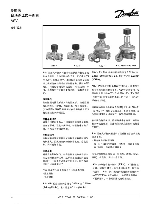
ASV-PV Plus的出厂设定为0.3bar(30kPa), 差压可在0.2bar-0.4bar(20kPa至40kPa)之间 设定。
ASV-PV出厂设定为0.1bar(10kPa),差压可 在0.05bar-0.25bar(5kPa至25kPa)之间设定。
ASV-P的差压为固定值,0.1bar(10kPa)。 ASV-PF DN50的阀门见单独样本。
2,98x1,78 G 1/16
产品编号 003L8155 003L8156 003L8157 003L8158 003L8158 003L8146 003L8147 003L8148 003L8149 003L8149 003L8143
003L8141
003L8145
003L8152
003L8153
ASV - PV 的差压控制范围为 0.05bar 至 0.25bar (5kPa至25kPa)。出厂设定为0.1bar(10kPa)。
SIBC
VD.A1.T2.41 C Danfoss 11/03
1
参数表
订货
SIBC
自动差压式平衡阀 ASV
型号
DN
mk3v/sh
内螺纹 ISO7 / 1
产品编号
15
15
1.6
R p 1/2
003L7 601
20
2.5
R p 3/4
003L7 602
25
4.0
R p1
003L7 603
32
6.3
R p1 1/4
003L7 604
40
10
R p1 1/2
003L7 605
型号
内螺纹 ISO228 / 1
G 1/2A
OMEGA PV100 电子控制比例阀说明书
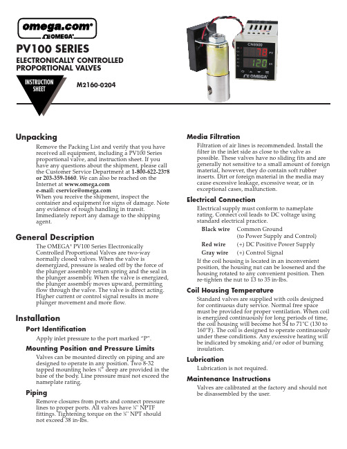
PV100 SERIES ELECTRONICALLY CONTROLLEDPROPORTIONAL VALVESUnpackingRemove the Packing List and verify that you havereceived all equipment, including a PV100 Seriesproportional valve, and instruction sheet. If youhave any questions about the shipment, please callthe Customer Service Department at 1-800-622-2378or 203-359-1660. We can also be reached on theInternet at e-mail:******************When you receive the shipment, inspect thecontainer and equipment for signs of damage. Noteany evidence of rough handling in transit.Immediately report any damage to the shippingagent.General DescriptionThe OMEGA®PV100 Series ElectronicallyControlled Proportional Valves are two-waynormally closed valves. When the valve isdeenergized, pressure is sealed off by the force ofthe plunger assembly return spring and the seal inthe plunger assembly. When the valve is energized,the plunger assembly moves upward, permittingflow through the valve. The valve is direct acting.Higher current or control signal results in moreplunger movement and more flow.InstallationPort IdentificationApply inlet pressure to the port marked “P”.Mounting Position and Pressure Limits Valves can be mounted directly on piping and aredesigned to operate in any position. Two 8-32tapped mounting holes 1⁄4” deep are provided in thebase of the body. Line pressure must not exceed thenameplate rating.PipingRemove closures from ports and connect pressurelines to proper ports. All valves have 1⁄8" NPTFfittings. Tightening torque on the 1⁄8" NPT shouldnot exceed 38 in-lbs.Media FiltrationFiltration of air lines is recommended. Install thefilter in the inlet side as close to the valve aspossible. These valves have no sliding fits and aregenerally not sensitive to a small amount of foreign material, however, they do contain soft rubberinserts. Dirt or foreign material in the media maycause excessive leakage, excessive wear, or inexceptional cases, malfunction.Electrical ConnectionElectrical supply must conform to nameplaterating. Connect coil leads to DC voltage usingstandard electrical practice.Black wire Common Ground(to Power Supply and Control) Red wire(+) DC Positive Power SupplyGray wire(+) Control SignalIf the coil housing is located in an inconvenientposition, the housing nut can be loosened and thehousing rotated to any convenient position. Thenre-tighten the nut to 13 to 35 in-lbs.Coil Housing TemperatureStandard valves are supplied with coils designedfor continuous duty service. Normal free spacemust be provided for proper ventilation. When coil is energized continuously for long periods of time, the coil housing will become hot 54 to 71°C (130 to 160°F). The coil is designed to operate continuously under these conditions. Any excessive heating will be indicated by smoking and/or odor of burninginsulation.LubricationLubrication is not required.Maintenance InstructionsValves are calibrated at the factory and should notbe disassembled by the user.Available ModelsFlow Ranges,SCCM Model Orifice Maximum At Maximum At Number Millimeters Inches C v Pressure Pressure10 PSI PV101-(*).801/320.02200 PSI0-50,0000-8,000 PV102-(*) 1.193/640.045100 PSI0-65,0000-17,000 PV103-(*) 1.591/160.0860 PSI0-75,0000-30,000 PV104-(*) 1.985/640.1240 PSI0-80,0000-45,000 *Specify Control Signal:MA for 4-20 MADC5V for 0-5 VDC10V for 0-10 VDCDimensions2SpecificationsValve Type:2-Way Normally ClosedWetted Parts:Stainless Steel with Viton SealsPower:12-24 VDCPower Consumption:7 Watts MaximumControl Signals:0-5 VDC, 0-10 VDC, 4-20 MADCAmbient Temperature Range:-10 to 50°C(14 to 122°F)Media Temperature Range:-18 to 82°C(0 to 180°F)Linear Control Range:15-85% of Full FlowResponse Time for Complete CycleOff - Full Open - Off:40 msec @ 0 pressure100 msec @ maximum pressureRepeatability:±5% when in operating linear control rangeElectrical Connection:18" color-coded lead wiresWiring:Red DC Power SupplyGray Control Signal (+)Black Common (to Power and Control) Pressure Connections:1⁄8" NPTFEnclosure:General Purpose, NEMA-13It is the policy of OMEGA Engineering, Inc. to comply with all worldwide safety and EMC/EMI regulations that apply. OMEGA is constantly pursuing certification of its products to the European New Approach Directives. OMEGA will add the CE mark to every appropriate device upon certification.The information contained in this document is believed to be correct, but OMEGA accepts no liability for any errors it contains, and reserves the right to alter specifications without notice.WARNING: These products are not designed for use in, and should not be used for, human applications.WARRANTY/DISCLAIMEROMEGA ENGINEERING, INC. warrants this unit to be free of defects in materials and workmanship for a period of 13 months from date of purchase.OMEGA’s WARRANT Y adds an additional one (1) month grace period to the normal one (1) year product warranty to cover handling and shipping time. This ensures that OMEGA’s customers receive maximum coverage on each product.If the unit malfunctions, it must be returned to the factory for evaluation. OMEGA’s Customer Service Department will issue an Authorized Return (AR)number immediately upon phone or written request. Upon examination by OMEGA, if the unit is found to be defective, it will be repaired or replaced at no charge. OMEGA’s WARRANTY does not apply to defects resulting from any action of the purchaser, including but not limited to mishandling,improper interfacing, operation outside of design limits, improper repair, or unauthorized modification. This WARRANTY is VOID if the unit shows evidence of having been tampered with or shows evidence of having been damaged as a result of excessive corrosion; or current, heat, moisture or vibration; improper specification; misapplication; misuse or other operating conditions outside of OMEGA’scontrol. Components in which wear is not warranted, include but are not limited to contact points, fuses, and triacs.OMEGA is pleased to offer suggestions on the use of its various products. However, OMEGA neither assumes responsibility for any omissions or errors nor assumes liability for any damages that result from the use of its products in accordance with information provided by OMEGA, either verbal or written. OMEGA warrants only that the parts manufactured by the company will be as specified and free of defects. OMEGA MAKES NO OTHER WARRANTIES OR REPRESENTATIONS OF ANY KIND WHATSOEVER, EXPRESSED OR IMPLIED, EXCEPT THAT OF TITLE, AND ALL IMPLIED WARRANTIES INCLUDING ANY WARRANTY OF MERCHANTABILITY AND FITNESS FOR A PARTICULAR PURPOSE ARE HEREBY DISCLAIMED. LIMITATION OF LIABILITY : The remedies of purchaser set forth herein are exclusive, and the total liability of OMEGA with respect to this order, whether based on contract, warranty, negligence, indemnification, strict liability or otherwise,shall not exceed the purchase price of the component upon which liability is based. In no event shall OMEGA be liable for consequential,incidental or special damages.CONDITIONS: Equipment sold by OMEGA is not intended to be used, nor shall it be used: (1) as a “Basic Component” under 10 CFR 21 (NRC), used in or with any nuclear installation or activity; or (2) in medical applications or used on humans. Should any Product(s) be used in or with any nuclear installation or activity, medical application, used on humans, or misused in any way, OMEGA assumes no responsibility as set forth in our basic WARRANT Y/DISCLAIMER language, and, additionally, purchaser will indemnify OMEGA and hold OMEGA harmless from any liability or damage whatsoever arising out of the use of the Product(s) in such a manner.Servicing North America:U.S.A.:One Omega Drive, Box 4047ISO 9001 CertifiedStamford, CT 06907-0047Tel: (203) 359-1660FAX: (203) 359-7700e-mail:**************Canada:976 BergarLaval (Quebec) H7L 5A1, Canada Tel: (514) 856-6928FAX: (514) 856-6886e-mail:*************For immediate technical or application assistance:U.S.A. and Canada:Sales Service: 1-800-826-6342 / 1-800-TC-OMEGA ®Customer Service: 1-800-622-2378 / 1-800-622-BEST ®Engineering Service: 1-800-872-9436 / 1-800-USA-WHEN ®TELEX: 996404 EASYLINK: 62968934 CABLE: OMEGAMexico:En Espan ˜ol: (001) 203-359-7803e-mail:*****************FAX: (001) 203-359-7807**************.mxOMEGAnet ®Online Service Internet e-mail***********************Servicing Europe:Benelux:Postbus 8034, 1180 LA Amstelveen, The Netherlands Tel: +31 (0)20 3472121FAX: +31 (0)20 6434643Toll Free in Benelux: 0800 0993344e-mail:*****************Czech Republic:Frystatska 184, 733 01 Karviná, Czech Republic Tel: +420 (0)59 6311899FAX: +420 (0)59 6311114Toll Free: 0800-1-66342e-mail:*****************France:11, rue Jacques Cartier, 78280 Guyancourt, France Tel: +33 (0)1 61 37 2900FAX: +33 (0)1 30 57 5427Toll Free in France: 0800 466 342e-mail:**************Germany/Austria:Daimlerstrasse 26, D-75392 Deckenpfronn, GermanyTel: +49 (0)7056 9398-0FAX: +49 (0)7056 9398-29TollFreeinGermany************e-mail:*************United Kingdom:One Omega Drive, River Bend Technology CentreISO 9002 CertifiedNorthbank, Irlam, Manchester M44 5BD United Kingdom Tel: +44 (0)161 777 6611FAX: +44 (0)161 777 6622Toll Free in United Kingdom: 0800-488-488e-mail:**************.ukRETURN REQUESTS /INQUIRIESDirect all warranty and repair requests/inquiries to the OMEGA Customer Service Department. BEFORE RETURNING ANY PRODUCT (S) T OOMEGA, PURCHASER MUST OBTAIN AN AUTHORIZED RETURN (AR) NUMBER FROM OMEGA’S CUSTOMER SERVICE DEPARTMENT (IN ORDER T O AVOID PROCESSING DELAYS). T he assigned AR number should then be marked on the outside of the return package and on any correspondence.The purchaser is responsible for shipping charges, freight, insurance and proper packaging to prevent breakage in transit.FOR WARRANTY RETURNS, please have the following information available BEFORE contacting OMEGA:1.Purchase Order number under which the product was PURCHASED,2.Model and serial number of the product under warranty, and3.Repair instructions and/or specific problems relative to the product.FOR NON-WARRANTY REPAIRS,consult OMEGA for current repair charges.Have the following information available BEFORE contacting OMEGA:1. Purchase Order number to cover the COST of the repair,2.Model and serial number of the product, and3.Repair instructions and/or specific problems relative to the product.OMEGA’s policy is to make running changes, not model changes, whenever an improvement is possible. T his affords our customers the latest in technology and engineering.OMEGA is a registered trademark of OMEGA ENGINEERING, INC.© Copyright 2004 OMEGA ENGINEERING, INC. All rights reserved. This document may not be copied, photocopied, reproduced, translated, or reduced to any electronic medium or machine-readable form, in whole or in part, without the prior written consent of OMEGA ENGINEERING, INC.。
丹佛斯产品册中文
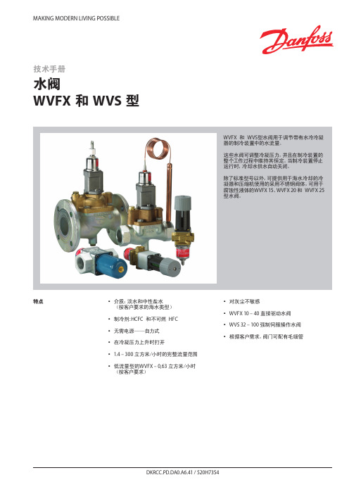
MAKING MODERN LIVING POSSIBLE特点y y介质:淡水和中性盐水(按客户要求的海水类型)yy y制冷剂:HCFC y和不可燃y HFC yy y无需电源——自力式yy y在冷凝压力上升时打开yy 1.4 – 300 立方米/小时的完整流量范围yy y低流量型的WVFX – 0,63 立方米/小时y(按客户要求)yy y对灰尘不敏感yy WVFX 10 – 40 直接驱动水阀yy WVS 32 – 100 强制伺服操作水阀y y y根据客户需求,阀门可配有毛细管技术手册水阀WVFX 和 WVS 型WVFX y和y WVS型水阀用于调节带有水冷冷凝器的制冷装置中的水流量。
这些水阀可调整冷凝压力,并且在制冷装置的整个工作过程中维持其恒定。
当制冷装置停止运行时,冷却水供水自动关闭。
除了标准型号以外,可提供用于海水冷却的冷凝器和压缩机使用的采用不锈钢阀体,可用于腐蚀性液体的WVFX 15、WVFX 20 和y WVFX 25型水阀。
参数表 水阀,WVFX 和 WVS 型技术参数1) k v值为水在通过阀的压差等于 1 bar时的流量,单位为[立方米/小时],密度ρ = 1000 千克/立方米。
2)完全打开阀则需要比使用压力范围为 3.5-16 bar的WVFX阀压力高y33%y的压力,3) WVFX 15、WVFX 20 和y WVFX 25型水阀可提供不锈钢阀体。
WVFX 10 – 40 为直接驱动调节阀yWVS 32 – 100 为伺服操作调节阀介质温度范围yWVFX 10 – 25: -25 – 130 °C yWVFX y32 – 40: -25 – 90 °C yWVS:y y-25 – 90 °C y如果一个WVS型调节器需要 1 - 10 bar y的开启压力差时,y必须更换阀的伺服弹簧。
见“订货”部分。
开启压力差yWVFX 10 – 25:yy最大 10 bar y WVFX 32 – 40:yy最大 10 bar y WVS 32 – 40:yy最小 0.5 bar:y y最大 4 bar y WVS 50 – 100:yy最小 0.3 bar;y y最大 4 bar y低于最大负荷的 20% 时,WVSy实际上将作为一个开关调节器。
丹佛斯Danfoss动态压差平衡阀ASV参数表-水力平衡
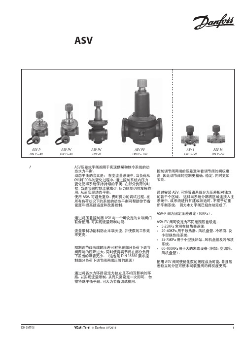
图 4 ASV用于地板采暖系统中分集水器前
ASV 阀用于地板采暖系统。为实现对每个环路的 流量限制,应将带有预设定的分集水器与 ASV-PV 阀提供的恒定压差控制配合使用。或者通过使用
具有设定功能 ASV-I 实现对整个分集水器的流量 限制。
如需不同的设定压差,ASV-PV 的设定压差具有数 个的可选范围。由于尺寸紧凑,ASV 动态压差平衡 阀易于安装于挂墙的分集水器安装盒内。
型号
备注
螺纹尾管(1 件)
焊接尾管(1 件)
连接至管道 R½ R¾ R1 R 1¼ R 1½
R2
DN 15 DN 20 DN 25 DN 32 DN 40
DN 50
注意: ASV-PV DN 50 (2½”) 和 ASV-I/M DN 50 (2¼”) 的接头口径不同。 1) 与 ASV-PV DN 50 阀配套使用 2) 与 ASV-I 和 ASV-M DN 50 配套使用。
ASV-P 阀为固定压差设定(10KPa)。
ASV-PV 阀可设定为不同范围压差设定: • 5-25KPa 常用在散热器系统, • 20-40KPa 用于散热器、风机盘管、冷吊顶、及
小型换热站系统, • 35-75KPa 用于小型换热站、风机盘管及冷吊顶
系统, • 60-100KPa 用于大的末端设备(例如:空调箱、
22
VD.A1.T8.41 © Danfoss 07/2013
DH-SMT/SI
DH-SMT/SI
VD.A1.T8.41 © Danfoss 07/2013
3
参数表 描述 / 应用 (续)
动态压差平衡阀 ASV
参数表
保温材料
图 +5 ASV 用于风机盘管系统
Danfoss 多压力放行阀值用户手册说明书
Revised 11/01/85AX437060129637en-000101Multi-Pressure Relief ValvesCG-(H)-06-*(V)-(P)*DG(L)-0*-(H)-*-20CG-(H)-10-*(V)-(P)*DG(L)-0*-(H)-*-20Parts Manualby Danfoss#3DG4S4-010N-*-51Pilot Valve(Refer to I-3471-S for parts information)DG4S4-010A-*-50Pilot Valve(Refer to I-3478-S for parts information)Model CodeFor satisfactory service life of these components in industrial applications,use full flow filtrationto provide fluid which meets ISO cleanliness code18/15or cleaner.Printed in U.S.A.Danfoss Power Solutions is a global manufacturer and supplier of high-quality hydraulic and electric components.We specialize in providing state-of-the-art technology and solutions that excel in the harsh operating conditions of the mobile off-highway market as well as the marine sector.Building on our extensive applications expertise,we work closely with you to ensure exceptional performance for a broad range of applications.We help you and other customers around the world speed up system development,reduce costs and bring vehicles and vessels to market faster.Danfoss Power Solutions –your strongest partner in mobile hydraulics and mobile electrification.Go to for further product information.We offer you expert worldwide support for ensuring the best possible solutions foroutstanding performance.And with an extensive network of Global Service Partners,we also provide you with comprehensive global service for all of our components.Local address:DanfossPower Solutions GmbH &Co.OHG Krokamp 35D-24539Neumünster,Germany Phone:+4943218710DanfossPower Solutions ApS Nordborgvej 81DK-6430Nordborg,Denmark Phone:+4574882222DanfossPower Solutions (US)Company 2800East 13th Street Ames,IA 50010,USA Phone:+15152396000DanfossPower Solutions Trading (Shanghai)Co.,Ltd.Building #22,No.1000Jin Hai Rd Jin Qiao,Pudong New District Shanghai,China 201206Phone:+862120806201Danfoss can accept no responsibility for possible errors in catalogues,brochures and other printed material.Danfoss reserves the right to alter its products without notice.This also applies to products already on order provided that such alterations can be made without subsequent changes being necessary in specifications already agreed.All trademarks in this material are property of the respective companies.Danfoss and the Danfoss logotype are trademarks of Danfoss A/S.All rights reserved.Products we offer:•Cartridge valves •DCV directional control valves•Electric converters •Electric machines •Electric motors •Gear motors •Gear pumps •Hydraulic integrated circuits (HICs)•Hydrostatic motors •Hydrostatic pumps •Orbital motors •PLUS+1®controllers •PLUS+1®displays •PLUS+1®joysticks and pedals•PLUS+1®operator interfaces•PLUS+1®sensors •PLUS+1®software •PLUS+1®software services,support and training •Position controls and sensors•PVG proportional valves •Steering components and systems •TelematicsHydro-Gear Daikin-Sauer-Danfoss。
丹佛斯Danfoss生活热水循环系统多功能恒温阀MTCV-水力平衡
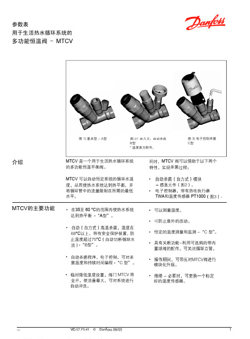
多功能恒温阀 - MTCV
50 ˚C下 在 35 ˚C下
在 60˚C下
流 量 水 温 温 度 ˚C
预设
预设
预设
预设
预设
预设
水温 ˚C
流量温度 ˚C
B型 C型
数据表 计算举例
多功能恒温阀 - MTCV
8 个立管进行计算。
VD.57.X1.02
•
q1 =10
*
*
- 管路的尺寸 - 绝热层的材料 - 装管子处的环境温度 - 绝热层的效率和条件
•
Tsup = 55 °C
•
∆T= 5 K
•
•
l = 10 m
•
I 基本操作
• 每个立管中热量损失的计算
Qr
Qh
Qr = l立管x q = (10+10) x10 = 200 m
Qh= l 水平 x q = 10 x 10= 100 m
•表3
立管
立管中 Qr
顶部 Qh
热量损失 每一部分的 总的损失
ΣQ 总
阀 – 基本型A型
产品编号
阀体 ................................................Rg 5 O型密封圈 ...................................EPDM
. 不锈钢
高温杀菌模块 -B型
描述
产品编号
ESMB PT1000用插座
CCR2控制器
• 模块化升级。
• 好的温度传感器。
数据表 功能
多功能恒温阀 - MTCV
1-A型。
当水温比设定值高 5°
MTCV 是一种自力式比例控制的恒温控制
- 1、下载文档前请自行甄别文档内容的完整性,平台不提供额外的编辑、内容补充、找答案等附加服务。
- 2、"仅部分预览"的文档,不可在线预览部分如存在完整性等问题,可反馈申请退款(可完整预览的文档不适用该条件!)。
- 3、如文档侵犯您的权益,请联系客服反馈,我们会尽快为您处理(人工客服工作时间:9:00-18:30)。
修订内容 更改代码 新的封底 添加4页: 应用安全章节 大幅修订 大幅修订
版本号 CD CF DA DB EA
样本修订
PVG产品的样本修订
名称 PVG 32 农机模块-公制油口 PVG 100 比例阀 PVG 120 比例阀 PVBZ 基本模块 PVSK 模块,集成了分流和P口切断功能 PVED-CC 电控模块 PVED-CX 电控模块,系列 4 PVE 系列 4 PVPV / PVPVM 泵侧模块 PVHC 电控模块,用于PVG32和PVG100 PVGI 过渡模块 PVSP/M 优先模块 PVBM “Meter-in” “Meter-out” 模块 类型 产品样本 维修手册 产品样本 产品样本 产品样本 产品样本 产品样本 产品样本 产品样本 产品样本 产品样本 产品样本 样册 代码 11051935 11048807 520L0356 520L0721 520L0556 520L0665 11070179 520L0553 520L0222 11064912 520L0405 520L0291 L1117392
PVG 100 功能
PVG 100 阀组带开芯 PVPF .............................................................................................................................................9 PVG 100 阀组带闭芯 PVPV / PVPVP / PVPVM ....................................................................................................... 11 PVG 100 闭芯转向优先模块 PVPVP ................................................................................................................. 12 PVG 100 闭芯模块 PVPVM ................................................................................................................................... 12 PVG 100 工作模块 PVB ........................................................................................................................................... 12 PVG 100 回油模块 ................................................................................................................................................... 12 负载敏感控制................................................................................................................................................................... 14 远程压力补偿控制 ......................................................................................................................................................... 15 远程压力补偿系统特性: ........................................................................................................................................ 15 典型实例:远程压力补偿系统........................................................................................................................... 15 PVG 100 主阀芯,带压力补偿控制......................................................................................................................... 16 压力补偿系统特性 ................................................................................................................................................... 16 典型实例:压力补偿系统 .................................................................................................................................... 16 PVMR, 摩擦定位 .............................................................................................................................................................. 17 PVMF, 机械浮动位置锁定. ......................................................................................................................................... 17 PVBS, 流量控制主阀芯 (标准)................................................................................................................................. 18 PVBS, 流量控制主阀芯 (线性特性) ............................................................................................................................. 18 安全建立 ............................................................................................................................................................................ 19 FMEA (故障模式及影响分析) IEC EN 61508 ................................................................................................... 19 故障模式及影响分析 ISO 12100-1 / 14121..................................................................................................... 19 实例:控制系统. ........................................................................................................................................................... 20 PVG 100 – LS卸荷或先导油切断可选 ............................................................................................................... 22
MAKING MODERN LIVING POSSIBLE
产品样本
比例阀 PVG 100
产品样ቤተ መጻሕፍቲ ባይዱ 修订版本
修订版本
PVG 100 比例阀
修订日期 2010年1月 2010年12月 2011年9月 2013年3月 2013年8月
页码 14, 17, 41 44 39-42 All All
PVG 100样本中含有带T0通道的模块,更多关于T0通道的内容请见 PVG 32 公制油口, 11051935 和 PVBZ 基本模块, 520L0721.
2
11034399 • EA • Aug 2013
产品样本 内容
概述
PVG 100 比例阀
缩写 .........................................................................................................................................................................................6 概述 .........................................................................................................................................................................................7 阀组系统 .........................................................................................................................................................................7 PVG 100 综合特性, 负载独立的流量控制 ..........................................................................................................7 PVP - 泵侧模块 .............................................................................................................................................................7 PVB – 工作模块 .............................................................................................................................................................8 驱动模块 .........................................................................................................................................................................8 远程控制单元 ...............................................................................................................................................................8