释锐CAS实战4.0
神舟链威C4000手持终端用户手册说明书

SHENZHEN CHAINWAY INFORMATION TECHNOLOGY CO., LTDC4000 Handheld TerminalUser Manual1ContentsStatement (4)1.Getting Started (6)1.1 Brief Instruction (6)1.2Precaution before Using Battery (7)2.About The Device (8)2.1 Structure (8)2.2 SD Card Installation (10)2.3 SIM Card Installation (11)2.4 Battery Installation (12)2.5 Battery Charging (13)2.5.1 Direct Charging (13)2.5.2 Cradle Charging (13)2.6 Device Power on/off (13)3.Call Function (14)3.1 Phone (14)3.2 Contacts (15)3.3 Messaging (16)4. Barcode Reader (17)4.1 1D Barcode (17)4.2 2D Barcode (18)4.3 2D(S) Barcode (19)5.RFID Reader (20)5.1 Low Frequency (20)25.2 High Frequency (22)5.2.1 14443A (22)5.2.215693 (23)5.3 Ultra High Frequency (24)6.Fingerprint Reader (26)7.Other Functions (27)7.1 PING (27)7.2Bluetooth (28)7.3 GPS (30)7.4 Volume Settings (31)7.5 Sensor (32)7.6 Keyboard (33)7.7 Network (34)7.8 Keyboardemulator (35)8. Device Specifications (36)3Statement2013 by Shenzhen Chainway Information Technology Co., Limited. All rights reserved.No part of this publication may be reproduced or used in any form, or by any electrical or mechanical means, without permission written from Shenzhen Chainway. This includes electronic or mechanical means, such as photocopying, recording, or information storage and retrieval systems. The material in this manual is subject to change without notice.The software is provided strictly on an “as is” basis. All software, including firmware, furnished to the user is on a licensed basis. Shenzhen Chainway grants to the user a non-transferable and non-exclusive license to use each software or firmware program delivered hereunder (licensed program). Except as noted below, such license may not be assigned, sublicensed, or otherwise transferred by the user without prior written consent of Shenzhen Chainway. No right to copy a licensed program in whole or in part is granted, except as permitted under copyright law. The user shall not modify, merge, or incorporate any form or portion of a licensed program with other program material, create a derivative work from a licensed program, or use a licensed program in a network without written permission from Shenzhen Chainway.Shenzhen Chainway reserves the right to make changes to any software or product to improve reliability, function, or design.Shenzhen Chainway does not assume any product liability arising out of, or in connection with, the application or use of any product, circuit, or application described herein.No license is granted, either expressly or by implication, estoppel, or otherwise under any Shenzhen Chainway intellectual property rights. An implied license only exists for equipment, circuits, and subsystems contained in Shenzhen Chainway products.Shenzhen Chainway Information Technology Co., LtdAddress: 9/F, Building 2, Phase 2, Gaoxinqi Industrial Park, Liuxian 1st Rd, District 67, Bao’an, Shenzhen, Guangdong, ChinaTelephone:+0086-755-23223300 Fax: +0086-755-23223310Web Site: Email:*******************451. G etting Started1.1 Brief InstructionChainway C4000 is a series of Android powered smart terminals, with data capture, data processing, wireless communication. It is with high-reliability &high-expansibility. Auto & Accurate data collection is achieved in various business fields via a complete solution of premium options, the flexible solution among options and operators is suited-up. You will find out with C4000, much easier deployment, reduced complexity, decreased maintenance, are the benefits for enterprises.C4000 meets industrial level IP64 (IEC sealing), is sufficient to routine applications, eg, railway inspection, road parking toll, vehicle inspection, logistics express, power inspection, warehousing management, chain retail, etc. Whether the mobile operators are working indoor or outdoor, with Chainway C4000, your business is always &highly efficient on-line.Meeting industrial standards, designed to support a various of mobile solutions. With the build-in high performance Cortex-A7 1.3GHZ quad core processor technology, the operators need only one device to enjoy a convenient and easy job, C4000 will be the ideal choice for key-fact business in mobile solutions, for simplified task flow, enhanced work efficiency, for shortened time to customer response, more satisfied customer care service.Chainway C4000 comes with world wide band WCDMA technology. Multi channels data and voice communication guarantees the real-time communication and data efficiency, C4000 brings you the best ROI.61.2 Precaution before Using Battery•Do not leave batteries unused for extended periods of time, either in the product or in storage. When the battery has been unused for 6 months, check the charge status and charge or dispose of the battery as appropriate. •The typical estimated life of a Lithium-Ion battery is about two to three years or 300 to 500 charge cycles, whichever occurs first. One charge cycle is a period of use from fully charged, to fully discharged, and fully recharged again. Use a two to three year life expectancy for batteries that do not run through complete charge cycles.•Rechargeable Lithium-Ion batteries have a limited life and will gradually lose their capacity to hold a charge. This loss of capacity (aging) is irreversible. As the battery loses capacity, the length of time it will power the product (run time) decreases.•Lithium-Ion batteries continue to slowly discharge (self-discharge) when not in use or while in storage. Routinely check the battery’s charge status. The user manual typically includes information on how to check battery status, as well as battery charging instructions.•Observe and note the run time that a new fully-charged battery provides for powering your product. Use the new battery run time as a basis to compare run times for older batteries. The run time of your battery will vary depending on the product’s configuration and the applications that you run. •Routinely check the battery’s charge status. Carefully monitor batteries that are approaching the end of their estimated life.Consider replacing the battery with a new one if you note either of thefollowing conditions:The battery run time drops below about 80% of the original run time.•The battery charge time increases significantly.•If a battery is stored or otherwise unused for an extended period, be sure to follow the storage instructions in this document. If you do not follow theinstructions, and the battery has no charge remaining when you check it,consider it to be damaged. Do not attempt to recharge it or to use it. Replace it with a new battery.•Always follow the charging instructions provided with your product. Refer to your product’s user manual and/or online help for detailed information about charging its battery.•Charge or discharge the battery to approximately 50% of capacity before storage. Charge the battery to approximately 50% of capacity at least once every six months.•Remove the battery and store it separately from the product.•Store the battery at temperatures between 5 °C and 20 °C (41 °F and 68 °F).72. A bout The Device2.1 Structure<Front>89<Back>Buttons:ButtonFunctionPower ButtonPress and hold to turn the device on or off App List View Button View a list of apps running Home ButtonPress to return to the home screen Cancel ButtonTap to return to the previous screenDetailed installation steps are as follows:•Open the SIM slot as the direction of ‘Open/Lock’ labeled.•Open the SD slot as the direction of ‘Open/Lock’ labeled.•Install the SD card properly.•Lock the SD slot and SIM slot properly.101. Open the SIM slot as the direction of ‘Open/Lock’ labeled.2. Install the SIM card correctly.3. Lock the SIM slot properly.2 3112.4 Battery Installation1. Push the battery down into the bottom of the battery.2. Push the battery to the direction of the array.3. Turn the battery lock.122.5 Battery Charging2.5.1 Direct ChargingUse the adapter to charge the battery via the USB connector of the snap-on. 2.5.2 Cradle ChargingConnect the adapter with the power cable to charge the device.2.6 Device Power on/offPress the ‘Power’ button on the side shortly due to turn on/off.13143. C all Function3.1 Phone1. Click this icon.2. Click the number button to input the numbers.3. Click the button to confirm and dial.4. Click theto end the calling.Contacts LogsVoice CallingEmulated Numeric Keypad3.2 Contacts1. Click ‘Contacts’ to open the contacts list.2. Click ‘’ to add the new contact.3. Click ‘’ to import/export or delete the contact list.FavoritesContact List Group153.3 Messaging1. Click ‘’ to open the message list.2. Click ‘’ to input the content.3. Click ‘’ to send the message.4. Click ‘’ to add photos, videos.164. Barcode Reader4.1 1D Barcode1. Open the 1D Barcode Demo in Appcenter.2. Press the ‘Scan’ button to start scanning, then the auto interval parameterscan also be set.174.2 2D Barcode1. Open the 2D Barcode Demo in Appcenter.2. Press the ‘Scan’ button to start scanning, then the auto interval parameterscan also be set.184.3 2D(S) Barcode1. Open the 2D(S) Barcode Demo in Appcenter.2. Press the ‘Scan’ button to start scanning, then the auto interval parameterscan also be set.3. Also, the barcode types enabling/disabling can also be set.Note: Please scan the barcode in a correct way, otherwise the scanningmight be failed.19205. R FID Reader5.1 Low Frequency1. Open the RFID_LF Demo within Appcenter and then press the ‘Scan’ button tostart reading.2. Tag types including ID Card/Animal Tag/Hitag/HDX Tag/EM4450 can be alsoselected, and Hitag-S and EM4305 reading/writing are already supported by the device.Please ensure that the LF module is embedded in the device, also please select the tag type correctly, otherwise the operation might not work. Meanwhile, please pay attention to the HDX and FDX-B since they are using different hardware due to the different working principles.215.2 High Frequency5.2.1 14443A1. Open the 14443A demo within Appcenter, and press the ‘Scan’ button to startreading.2. Mifare and Ultra Light reading/writing are also supported.225.2.2 156931. Open the RFID_15693 demo within Appcenter, and press the ‘Scan’ button tostart scanning.2. 15693 writing are also supported.235.3 Ultra High Frequency1. Open the UHF demo within Appcenter, and press the ‘Start’ button to startscanning.2. Multiple tags reading and single tag reading/writing are also supported.2425266. F ingerprint Reader1. Open the Fingerprint Demo in Appcenter.2. Put the finger to the fingerprint module and set the ID/name of the templateunder ‘ACQUISITION’.3. Put the finger to the fingerprint module properly and identify by ID/Name/Scoreunder ‘IDENTIFICATION’.4. The local templates can also be checked under ‘Data’.Please be aware that ISO standards are only supported by devices with ISO fingerprint hardware modules.7. O ther Functions7.1 PING1. Open the Ping in Appcenter.2. Set the Ping parameters and select the internal/external addresses.277.2 Bluetooth1. Open the Bluetooth demo in Appcenter and turn on the Bluetooth.2. Input the content or select the file, then scan the nearby Bluetooth printer andpair them.3. Select the printer and click ‘Print’ to print the content.2829307.3 GPS1. Open the GPS demo in Appcenter and turn on GPS module.2. Set the GPS parameters and get the GPS data information.7.4 Volume Settings1. Open the Volume Setting demo in Appcenter.2. Set the volumes based on the requirements.317.5 Sensor1. Open the Sensor demo in Appcenter.2. Test the sensor based on the requirements.321. Open the Keyboard demo in Handset Appcenter.2. Set and test the key values of the device.331. Open the Network demo in Appcenter.2. Test the WIFI/Mobile signal based on the requirements.34357.8 KeyboardemulatorKeyboard Emulator can be used directly for multiple using environments and the output formats can include prefix/suffix/enter/tap can also be defined, please define the options properly based on the features of the device.1. Open the Keyboardemulator which is preinstalled in the device.2. Click the options correctly based on the features of the device hardware,please also press the physical button to define the scan button, then please define the output formats based on the requirements, finally click ‘Open’ to save and enable it.8. Device SpecificationsPhysical CharacteristicsDimensions 153mm*75mm*29mm/6.02*2.95*1.14in.Weight 286g/10.09oz. (includes main battery)Screen 4in.WVGA (480*800) TFT-LCD, capacitive dual touchKeyboard 3 function keys, 3 side buttonsBattery Main bat. (rechargeable li-ion polymer, 3.7V, 3200 mAh)Pistol bat. (rechargeable li-ion polymer, 3.7V, 5200 mAh)Expansion Slot MicroSD/TF, maximum capacity of 32GSIM Slot 1 PSAM, 1 SIM, 1 MicroSDAudio 0.5WCamera OV 8M pixels, auto focus with LED flashPerformance CharacteristicsCPU Cortex-A7 1.3GHz quad coreOS Android 4.4.2Memory 1GB RAM, Build-in 4GB FlashInterface USB Micro-B, serial port RS-232(TTL)Storage Card Type MicroSD cardMaximum Expansion Storage 32GBUser Environmental CharacteristicsOperating Temperature -10℃to 50℃Storage Temperature -40℃to 70℃Humidity 5%RH-95%RH(non-condensing)Dropping Survive 1.2m/3.9ft. drop, 6 sides (concrete floor under operating temp.)Sealing IP64, IEC complianceWireless CommunicationWAN WCDMA/HSDPA/HSPA+ (850/1900/2100MHz)GSM/GPRS/EDGE (850/900/1800/1900MHz)WLAN IEEE802.11b/g/n, internal antenna36WPAN Bluetooth v4.0 Low EnergyBluetooth 3.0+HSBluetooth v4.0 Low Energy (LE)Data CollectionBarcode Scan Engine 1D barcode(Symbol SE955, laser)(optional)2D CMOS laser scanner: Symbol SE4750(optional) Sensor resolution: 750 * 480Roll tolerance: 360ºRFID LF 125KHz/134.2KHz, HDX/FDX-B(optional)HF 13.56MHz, ISO14443A/ISO15693(optional)UHF 860-960MHz, EPC C1 GEN2/ISO18000-6C(optional) Developing EnvironmentSDK Chainway SDKProgramming Language JavaDeveloping Tool Eclipse37。
ZeroTech 三角瞄准镜系列说明书

ZEROTECH RIFLESCOPESINTRODUCTIONLIFETIME WARRANTYSCOPE FEATURESSETTING THE DIOPTREMOUNTING YOUR SCOPEADJUSTING PARALLAXZEROING YOUR RIFLELOCKING WINDAGE & ELEVATION TURRETS ZEROING THE WINDAGE TURRET THRIVE & THRIVE HD MODELS ILLUMINATION FEATURE LENS COVER & TURRET MULTI-TOOL SCOPE CARE RETICLES WARRANTY INFORMATION4 5 6 8 10 12 14 17 21 2325 2731 32 34PAGESWELCOME TO THE ZEROTECH RIFLESCOPE FAMILY!Customer First - We listened to you and came up with a family of riflescopes that will satisfy the needs of our most discerning and experienced customers.Backed by Experience - ZeroTech enjoys 55 years of experience in the Optics Market supplying high quality brands to retailers throughout Australia and the Asia Pacific.Built for the Australian Shooter - Designed and built to endure the harsh conditions of the Australian bush and the exacting demands of the precision shooter.Lifetime Warranty - Be safe in the knowledge that your scope is backed by our Triple A Lifetime Warranty: ‘ANY OWNER, ANY PROBLEM, ALWAYS COVERED’Bespoke Reticles - Practical reticles for the everyday shooter. Helping you putrounds on target!BACKED FOR LIFE!Be safe in the knowledge that your scope isbacked by our Triple A Lifetime Warranty:- F ully transferable, covers accidental damage aswell as defects in materials and workmanship.- N o receipt or warranty card is required.- W e will repair or replace product with equal orsimilar value and/or specifications.- We will return product to you at no charge.‘ANY OWNER, ANY PROBLEM,ALWAYS COVERED’ZEROTECH - INSTRUCTION MANUAL Zerotech_Int_Thrive/Thrive HD/Trace_V3_March_2021Locking Elevation Turret Locking Windage TurretMagnification Power Change Ring(side focus)Dioptre Adjuster Half Magnification Indicator (HMI) – Second Focal Plane (SFP) models only30mm MaintubeTRACE & TRACE ADVANCED FEATURESWindage Turret Cap Elevation Turret Half Magnification Indicator (HMI)Change Ring (side focus)Push Button Reticle Illumination (on illuminated models only)OcularDioptre AdjusterFlip up HD THRIVE & THRIVE HD FEATURESSet your magnification to the maximum power.If fitted, set the parallax turret to the infinity marker.Find a blank, featureless and bright surface, such as a white wall or clear blue skyand look through your scope for no more than 5 seconds at a time.NEVER LOOK THROUGH YOUR SCOPE DIRECTLY AT THE SUN.1.2.3.4.When briefly looking through the scope, the reticle should appear sharp and clear immediately. If the reticle is not immediately sharp and clear, twist the dioptreadjuster to bring the reticle into sharp focus. The dioptre adjuster has approximately 1¾ turns of adjustment. We recommend starting with the dioptre assembly twisted flush up against the ocular and making adjustments in an anticlockwise (towards the + symbol marked on the ocular) direction until the optimal setting is reached.Once you are satisfied the base(s) is correctly fitted to the receiver of your firearm,proceed to fit the rings to the base(s) and ensure the ring clamps are tightened to the recommend torque settings as specified by the manufacturer.With the ring tops removed, place the scope in the ring bases and gently slide thescope back and fourth in the ring bases to ensure the scope slides freely. If the scope does not slide freely, lapping of the rings may be necessary to avoid damage 1.2.to the scope maintube. ZeroTech always recommends the use of high quality rings and bases to ensure the best possible fitting of your scope.Avoid mounting the scope with the rings contacting the junction of the maintube/erectorhousing, magnification ring/maintube junction or the objective/maintube junction.It is essential to confirm that no part of the scope is contacting the barrel or receiverwhen the scope is mounted in the rings.Once you have confirmed the fit of the scope in the ring bases, fit the ring tops andtighten the ring top bolts to between 22 – 25 in lbs or 2.5 – 2.8NM.ZeroTech highly recommends the use of a scope level (bubble level) fitted to therings or the scope maintube to ensure the reticle can consistently be aligned with the fall of gravity every time a shot is fired. This is particularly important for precision shooting applications.*If your level mounts to the maintube of the scope, follow the same guidelines as observed for scope ring fitting to ensure the level does not damage the maintube of your scope.3.4.5.6.If your ZeroTech scope is fitted with a parallax turret, it is important to adjust the parallax turret for shots taken at different distances. Some shooters refer to the parallax turret as the ‘side focus’. It is referred to as the ‘side focus’ because by turning the turret, it will bring your target image into focus. As a general rule and as long as your dioptre is set correctly (refer to page 8 – ‘Setting the Dioptre’) the sharper the target image is focused, the parallax error will be less.Parallax error is quite easy to detect when following the instructions below;Acquire your target image at any distance and make sure your rifle is well supportedby the use of a bipod and rear bag (or similar).Use the parallax turret to obtain the sharpest/ clearest possible target image andestablish a refined point of aim on the target.Once you have established a refined point of aim and a sharp target image, move 1.2.your head gently up and down whilst looking through the scope. Be sure not to disturb the rifle/ sights.If you are able to observe the reticle departing slightly from the intended point of aim, make small adjustments on the parallax turret until the reticle remains fixed on your point of aim.You will need to repeat this process when shooting at different distances or in different environmental conditions. The distance markings on the parallax turret are intended asa guide only. Dioptre settings and environmental factors are likely to cause the distance markings to vary in relation to the actual distance of the target.Adjust the parallax turret to bring the target image into focus4.5.6.ZEROTECH - INSTRUCTION MANUALZEROING DISTANCESCentrefire rifles: Zerotech recommends zeroing most centrefire rifles at approximately 100 metres +/- 10 metres. 100 metres enables the shooter to overcome any offset problems caused by the centre height of the scope above bore but is not too far as to accidentally build in an error due to unobserved environmental conditions such as wind. Rimfire rifles: Most commonly, rimfire hunting rifles are zeroed at 50 – 75 metres depending on the type of ammunition being used. Rimfire target rifles may have different zeroing requirements depending on purpose.We always recommend that you zero your rifle in the same manner as you typically shoot your rifle. For example, if you mainly shoot your rifle from a bench, zero your rifle by shooting from a bench. If you predominately shoot your rifle inBefore you fire your first shot, you should bore sight your rifle to ensure your scope and your barrel are both aligned at the intended point of impact on your target. To do this with a bolt action rifle, remove the bolt with the rifle securely supported (front and rear) and align the bore with the target.Without disturbing the rifle, carefully look through the scope and check that the reticle is also aligned with the same point as the bore on the target. If the reticle is not aligned, use the windage end elevation adjustments on your scope to adjust the reticle to the intended point of impact on the target.Once you are satisfied that the scope and the bore of your rifle are aligned to the same point on the target, fire a shot at the target and observe the point of impact (bullet hole). If required, use the windage and elevation turrets on your scope to adjust the bullet impact.ZEROING DISTANCES CONTINUED...Dialling the elevation turret in the direction of the ‘U’ symbol will adjust the bullet impact upwards on the target. Likewise, dialling the windage turret in the direction of the ‘R’ symbol will adjust the bullet impact to the right on the target.�If your scope turrets are indexed in ¼ Minutes of Angle (0.25 MOA), each ‘click’ of your scope turret will adjust you bullet impact approximately 7-8mm at 100 metres (approx. ¼” at 100 yards).�If your scope turrets are indexed in 0.1 Milrad (0.1 MRAD), each ‘click’ of your scope turret will adjust your bullet impact 1cm at 100 metres (0.36” at 100 yards).Once you have established a zero for your rifle, the zero stop feature can be set to ensure a consistent return to zero after dialling the elevation turret to compensate forSETTING THE ZERO STOPRemove the elevation turret byloosening the three (3) opposinggrub screws located in the top ofthe elevation turret with a 2mmhex key. Remove the elevationturret and set aside.points. Loosen each grub screw 4 to 5 revolutions witha 2mm hex key.SETTING THE ELEVATION ZERO STOP 1.With the elevation turret removed, the orange zero stop ring will be visible. Similar tothe elevation turret cap, the orange zero stop ring also has three (3) opposing grub screws. Use your 2mm hex key to loosen the grub screws 1 to 2 revolutions each. This will allow the orange zero stop ring to spin freely.Slide the orange zero stop ring downwards until it stops. During this process, it isimportant to note the small black lug located on side of the orange zero stop ring. There is also a lug located the top face of the lower assembly, directly underneath the orange zero stop ring. It is critical that the lug on the side of the orange zero stop ring is positioned on the right hand side of the lug on the lower assembly. Failure to follow this step will result in the elevation adjustment being locked out and unusable until the zero stop is reset. If this occurs, simply position the lug on the orange zero stop ring on the other side of the lug on the lower assembly.Tighten the three (3) 2mm grub screws in the orange zero stop ring. The zerostop is now set.2.3.4.The zero stop is now set. Tighten the three 2mm grub screws and replace the elevationturret indexed to the ‘0’ position.Note the position of the lugs asdescribed in step 3.SETTING THE ZERO STOP CONTINUED...Loosen the three 2mm grub screws inthe orange zero stopand slide the zerostop downwards untilit stops.1. 2. 3.Replace the elevation turret and make sure to align the ‘0’ on the elevation turret cap to the vertical marker on the lower turret assembly to enable an easy and precise reference when dialling the elevation turret. Tighten the three (3) 2mm grub screws to secure the turret cap. We recommend using the short end of your hex key to apply adequate torque to the grub 2mm grub screws.5.The windage turret can be reset to ‘0’ without completely removing the windageturret cap from the scope. It is important to note that the windage turret does not have a zero stop feature as the turret needs to be able to adjust the bullet impact both left and right equally at all times.With the windage turret in the unlocked position, loosen the three (3) 2mm grubscrews approximately ½ - 1 revolution each. This will allow the windage turret to spin freely.With the windage turret spinning freely, align the ‘0’ on the turret with the indexline on the lower turret assembly and tighten the three (3) 2mm grub screws, using the short end of your hex key for adequate leverage.1.2.3.ZEROING THE WINDAGE TURRET CONTINUED...ZEROTECH - INSTRUCTION MANUALRESETTING THE TURRETS AFTER ZEROINGAfter you have followed the mounting and zeroing instructions on pages 14 – 16, you are ready to reset the elevation and windage turrets to zero (‘0’).Holding the turret in place, use the ZT multi-tool to unscrew the turret keeper anticlockwise. Remove the keeper and the turret. (For more info on ZT multi-tool see page 27).Replace the turret with the reference set to ‘0’ (zero). Replace and tighten the keeper using the ZT multi-tool. It is not necessary to overtighten the keeper.1.Check your turret to make sure the ‘0’ on the turret is aligned with the index markon the turret bodyRepeat this process for the windage turret.Replace the turret caps to ensure your zero settings aren’t disturbed.Make sure the ‘0’ marker aligns withthe index marker on the turret body.2.3.4.RESETTING THE TURRETS AFTER ZEROING CONTINUED...Thrive HD models fitted with the push button illumination function have 6 settings (5 illumination settings + OFF setting).Before use, install the CR2032 battery by removing the illumination turret batterycover. Unscrew in an anticlockwise direction.Press the illumination control button once to illuminate the reticle. You can thentoggle between the brightness settings by quickly pressing the button.IMPORTANT - To turn the reticle illumination off, press and hold the button for 2 – 3seconds.Models fitted with the push button illumination have an auto shutdown feature.The reticle will automatically power-off after 3 hours to avoid excessive battery consumption.Our push button illumination has a memory function that resumes on the samebrightness setting the next time the illumination is activated.1.2.3.4.5.Unscrew battery cap anticlockwise.Insert battery and replace illuminationturret cap.ILLUMINATION FEATURE CONTINUED...Various size lens coveradjustment toolVarious size lens coveradjustment toolKeyring holeThrive Series Turret Tool(THRIVE HD AND TRACE MODELS)Zerotech Thrive HD and Trace models are fitted with HD Alloy Flip Up lens covers. The HD Alloy lens covers are removable and can be rotated to the preferred position of the shooter. For example, some shooters prefer their objective flip up cover to fold out to the side of the scope instead of folding to the top.It is likely that you will also need to adjust the position of the ocular flip up cover after you have obtained the correct dioptre setting (as described on page 8).To adjust the position of the flip up lens covers, follow the steps below:If you wish to completely remove the flip up lens covers, simply use the multi-tool to rotate the lens cover lock ring in an anticlockwise direction until the lens cover completely detaches from the scope.Select the end of the multi-tool that fits the slots in the lock ring of your lens cover Loosen the lens cover lock ring by twisting the multi-tool in an anticlockwise direction Rotate the lens cover to the desired positionTighten the lens cover lock ring but twisting the multi-tool in a clockwise direction 1.2.3.4.USING THE ZEROTECH MULTI-TOOL TO RESET THE ELEVATION AND WINDAGE TURRETS (THRIVE SERIES ONLY)Once you have zeroed your rifle at the desired distance, it is recommended that you reset your elevation and windage turrets back to ‘0’. This gives the shooter the ability to use the turrets to precisely dial elevation and windage onto the scope when shooting at distances other than the zero distance for the rifle.To reset the turrets on the Thrive and Thrive HD models, you will require the Zerotech multi tool (or a coin). Follow the steps below.Holding the turret firmly, insert the multi tool into the slot in the turret centre bolt andcompletely remove the centre bolt but twisting the multi tool in an anticlockwise direction. Once the centre bolt has been removed, simply lift the turret away from the scope. Refit the turret to the scope, making sure to align the ‘0’ marking on the turret withthe index line on the scope body.Hold the turret firmly and tighten the centre bolt back down by twisting the multi tool1.2.3.4.SECOND FOCAL PLANE RETICLESAvailable in;THRIVE HD 2.5-15x50THRIVE HD 2.5-15x50 Illum.THRIVE HD 6-24x50THRIVE HD 6-24x50 Illum. THRIVE HD 3-18x56 Illum.VENGEANCE 4-20x50PHR-IIAvailable in;THRIVE 3-9x40THRIVE 3-12x44PHR 3Available in;TRACE 3-18x50TRACE 4.5-27x50THRIVE HD 3-18x56VENGEANCE 4-20x50VENGEANCE 4-20x50 Illum.R3Available in;THRIVE 3-12x44THRIVE 4-16x50MildotAvailable in;THRIVE 3-9x40THRIVE 3-12x44THRIVE 4-16x50DuplexSECOND FOCAL PLANE RETICLESFor specific information on your reticle, refer to the reticle spec sheet provided in your scope box or visit .auTHRIVE HD - 6-24x50For specific information on your reticle, refer to the reticle spec sheet provided in yourscope box or visit .auWipe dust and debris from your scope body using a damp microfibre cleaning cloth.If necessary, clean dust and dirt from the scope lenses using a lens brush andthe ZeroTech lens cleaning cloth.Never spray cleaners or solvents on any part of your scope. Irreversible damagemay be caused by such products.Avoid touching the scope lenses. Wipe fingerprints off the scope lenses using theZeroTech lens cleaning cloth.1.2.3.4.Ph: +612 9938 3244Email: ******************.auPlease direct all enquiries to ********************.au Company details;ZEROTECH INTERNATIONAL PTY LTDAddress: PO BOX 6176, Frenchs Forest, NSW, 2086AUSTRALIA.au。
SIR4中文说明书中文图最终版 (1)

高频电源安装操作运行维护手册
目录
1. 概述 .................................................................................................................................................................. 9 1.1. 型 号 .................................................................................................................................................... 10 1.2. SIR: 静 电 除 尘 器 控 制 装 置 系 列 的 一 员 ....................................................................................... 10
4. 电气数据 ........................................................................................................................................................ 26 4.1. 概 述 .................................................................................................................................................... 26 4.2. 电 源 电 流 ........................................................................................................................................... 27 4.3. 要 求 的 电 缆 ....................................................................................................................................... 27
os-b101_2012-10 DNV海洋结构物设计规范 Metallic Materials 钢制材料规范

Main changes
• — — — Ch.2 Sec.1: Transverse impact values included in Table B4 and Table C5. Combinations of grain refining elements to be in line with Ship Rules Pt.2 Ch.2. Figure 3d to be in line with Ship Rules Pt.2 Ch.2.
A. A A A A A A
Introduction ........................................................................................................................................ 9
Offshore Standard DNV-OS-B101, October 2012 Changes – Page 3
CHANGES
General
This document supersedes DNV-OS-B101, April 2009. Text affected by the main changes in this edition is highlighted in red colour. However, if the changes involve a whole chapter, section or sub-section, normally only the title will be in red colour.
© Det Norske Veritas AS October 2012 Any comments may be sent by e-mail to rules@
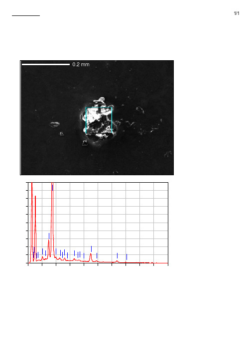
电泳颗粒EDX分析结果
Fe Fe
0 0.00 1.00 2.00 3.00 4.00 5.00 6.00 7.00 8.00 9.00 10 .00 keV ZA |!f [š‘ÏR F lÕ g• 0Õ0£0Ã0Æ0£0ó0.718 0° OÂep : 4 QC} (ke) Œê Ï Š¤î %SŸ[P S T ri V ‘% ] ep % Œê Ï 0«0Á0ª ‘% 0ó ep Na K 1.041 0.35 1.91 0.50 Al K 1.486 11.44 1.66 14.01 Si K 1.739 50.81 1.97 59.79 P K 2.013 0.92 2.83 0.98 Ti K 4.508 31.79 5.40 21.94 Fe K 6.398 4.69 11.96 2.77 TŠ 10 00 0. 10 00 0.
批注本地保存成功开通会员云端永久保存去通
0Ö 0Ä•è0 No1
1/1
0.2 mm 0.2 mm
-------------------------0¿0¤0È0ë : IM1 G -------------------------ˆÅ•n : 606 A 0(L ) R • –ûW' : 15. 00kV P s‡ : x 20 0 n,[šeåfB : 200 02/ 26 9/ u;} ep : 512 38 x 4 --------------------------
CPS
50 40 30 20 10 Fe g Ti M a TiFeN
Fe Fe
0 0.00 1.00 2.00 3.00 4.00 5.00 6.00 7.00 8.00 9.00 10 .00 keV ZA |!f [š‘ÏR F lÕ g• 0Õ0£0Ã0Æ0£0ó0.796 0° OÂep : 6 QC} (ke) Œê Ï Š¤î %SŸ[P S T ri V ‘% ] ep % Œê Ï 0«0Á0ª ‘% 0ó ep Na K 1.041 1.25 2.91 1.98 Mg K 1.253 0.65 2.41 0.97 Al K 1.486 17.45 2.41 23.57 Si K 1.739 17.06 2.88 22.13 P K 2.013 2.18 3.21 2.56 S K 2.307 0.50 2.72 0.57 Cl K 2.621 0.48 3.18 0.49 K K 3.312 0.59 4.35 0.55 Ca K 3.690 16.23 5.20 14.75 Ti K 4.508 36.76 7.14 27.96 Fe K 6.398 6.87 15.70 4.48 TŠ 10 00 0. 10 00 0.
Si操作手册

输入通道.........................................................................................3 ‐ 1
输入面板概述.................................................................................................. 3 ‐ 1 INPUT FADER SELECT输入推子选择按键(推子层选择).................. 3 ‐ 2 输入通道推子.................................................................................................. 3 ‐ 3 ON按键............................................................................................................ 3 ‐ 3 SOLO按键....................................................................................................... 3 ‐ 3 SELect按键...................................................................................................... 3 ‐ 4 输入通道状态窗口.......................................................................................... 3 ‐ 4 旋钮.................................................................................................................. 3 ‐ 4
合体版Zero4.0Final更新说明

57 附魔法术全面更改。不再有负效果,效果大幅提升但不可叠加(包括类似属性的相互叠加)
58 追加新武器——各种电锯。双手:[史诗]长柄电锯、[神话]碎尸者、[传说]肢解;单手:[史诗]便携电锯、[神话]电动斧刃I型、[神话]电动斧刃II型、[传说]时光切割者
38 原【英雄传说I II III】三套套装共六件装备全部更改建模,套装名称改为【达拉然的守卫者】【黑翼之巢的宝藏】【大元帅的指挥】,套装效果重写
39 原【盗贼之欲】套装武器模型更改,套装名称改为【堕落之欲】
40 弱化怪物的毒雾效果
41 暗夜行者初始武器改为手里剑(手持不显示,投掷时显示,剑类武器)
这个大概是最终版了吧……毕竟火炬2也差不多快出来了~~
谢谢大家一直以来的支持和帮助^_^
如果你玩过其他版本的火炬之光、mod或合体版的旧版本的话,建议人物洗点、宠物变回原版猫、狗、龙宠物,同时人物回到初始城镇
===============
4.0版相对3.0版的改动说明:
===============
46 圣骑士的【捍卫】【天使之剑】视觉效果修改
47 猎人追加【恐吓野兽】【毒蝎钉刺】【蝰蛇钉刺】【毒蛇钉刺】技能
48 战士【霜盾】技能效果增强(护甲加成增多)
50 雇佣兵营地的雇佣兵最高等级限制为30级,将不适应与高级怪物的战斗
51 去除所有人物的【炎爪】技能(如果有)。原因:和淬毒匕首效果重复
42 强化舞者的三大舞蹈基础伤害
43 追加新武器【狂野之斧】28级左右单手斧、【[传说]五管爆击炮】140级左右短射程高输出步枪、【[传说]战场狙击步枪】140级左右长射程步枪、【[传说]恶魔的诱惑】140级左右权杖、【[传说]无锋之剑】120级左右高输出单手剑
ACS4.1基本配置手册
Cisco ACS4.1基本配置手册1、ACS的基本设置在ACS服务器或远程PC上,IE浏览器URL中输入:http://acs服务器ip:2002可以进去ACS的配置界面,总的ACS界面如下图所示:图1-1deretsigeRnU1.1ACS软件基本选项设置1.1.1设置ACS4.1管理员帐号为了防止未经授权的人员配置ACS服务器,我们首先建立管理ACS的人员的帐号和密码,建立方式如下:(1) 进入ACS 管理控制栏目中,并点击右边ADD Administrator 选项: 图1-2(2) 输入管理员帐号密码,并点击Grant all 选项授予所有权限,最后Submit 提交一下:图1-3Un Re gi st er ed这样ACS 管理员帐号和密码就设置好了,下次通过远程登入ACS 界面系统就会提示需要提供管理员帐号和密码。
为了安全起见,可以考虑把ACS 网页超时时间设置的短一些,设置方法如下: (1) 点击图中的Seeeion Policy 选项,图1-4(2) 修改默认的idle timeout 时间,改成15min图1-5U n Re gi st er ed1.1.2 Log 信息的设置我们可以对ACS 对log 记录的默认设置进行一些修改,修改的步骤如下所示: (1) 进入ACS 的system configuration 栏目,并点击Service Contorl 选项: 图1-6(2) 对默认的LOG 记录选项按下图方式进行修改完后,点击Restart:图1-7U n R e gi st er ed1.1.3 高级用户选项设置为了ACS 用户属性等后续的设置需求,需要先把一些ACS 的高级用户选项开启一下:(1) 点击ACS 的Interface Configuration 栏目,可以看到右边有User DataConfiguration 和Advanced Options 这两个选项,如下图: 图1-8(2) 需要首先添加一个TACACS+属性的设备,这样上图中才会增加出另外一个TACACS+ (Cisco IOS)的选项。
- 1、下载文档前请自行甄别文档内容的完整性,平台不提供额外的编辑、内容补充、找答案等附加服务。
- 2、"仅部分预览"的文档,不可在线预览部分如存在完整性等问题,可反馈申请退款(可完整预览的文档不适用该条件!)。
- 3、如文档侵犯您的权益,请联系客服反馈,我们会尽快为您处理(人工客服工作时间:9:00-18:30)。
CAS实战4.0-增加了non-secure connection配置法2012年6月26号上海释锐教育软件有限公司内部培训教材CAS Server:192.168.18.55 :8080 apache-tomcat-7.0.25CAS Client:192.168.18.55 JBOSS5.1-GA目录一. 带证书的配置方法 (1)二. 不带证书的非加密传输(non-secure connection)配置方法 (9)一. 带证书的配置方法第1步:安装tomcat7 并配置好jdk1.7的环境变量。
第2步:创建证书注意事项:1、名字与姓氏必须填写验证服务器的域名2、密钥库口令是threenet@123第3步:导出证书至此导出证书完成,可以分发给应用的JDK使用了,接下来讲解客户端的JVM怎么导入证书第4步:为客户端的JVM导入证书注意事项:1、将.key.crt证书文件拷贝到客户端应用程序的机器上C:\jboss_test\jdk1.7.0\bin2、客户端的JRE密钥库默认口令是changeit 而非threenet@123至此证书的创建、导出、导入到客户端JVM都已完成,下面开始使用证书到Web服务器中,本教程使用tomcat如果不完成本步骤,运行应用系统时会出现如下错误:ng.RuntimeException:.ssl.SSLHandshakeException: sun.security.validator.ValidatorException: PKIX path building failed: sun.security.provider.certpath.SunCertPathBuilderException: unable to find valid certification path to requested target第5步:应用证书到CAS Web服务器-Tomcat,就是启用Web服务器(Tomcat)的SSL<!-- Define a SSL HTTP/1.1 Connector on port 8443This connector uses the JSSE configuration, when using APR, theconnector should be using the OpenSSL style configurationdescribed in the APR documentation --><Connector port="443" protocol="HTTP/1.1" SSLEnabled="true"maxThreads="150" scheme="https" secure="true"clientAuth="false" sslProtocol="TLS" keystoreFile="C:/apache-tomcat-7.0.25/keys/.key" keystorePass="threenet@123" />好了,到此Tomcat的SSL启用完成,现在你可以启动tomcat试一下了第6步:启动TOMCA T,发现如下错误:ng.Exception: Connector attribute SSLCertificateFile must be defined when using SSL with APR解决办法:注释掉一行配置Try this as your server.xml file. I removed some of the comments and commented out the APR listener.<!-- <Listener className="org.apache.catalina.core.AprLifecycleListener" SSLEngine="on" /> -->至此,测试一下打开https:///提醒:在该步骤,客户端浏览器用户可以按提示一步一步安装证书,安装成功后,下次就不会出现这个提示了。
接下来配置CAS服务器。
第7步:安装CAS服务器软件7-1)下载完成后将cas-server-3.4.11.zip解压,解压cas-server-3.4.11/modules/cas-server-webapp-3.4.11.war,然后复制到你的tomcat/webapp目录下。
7-2)CAS深入配置,配置CAS服务器怎么读取数据库的信息进行身份验证,修改cas/WEB-INF/deployerConfigContext.xml 文件。
先复制数据库驱动程序sqljdbc4.jar拷贝到tomcat7/lib下、cas-server-support-jdbc-3.4.11.jar、commons-dbcp.jar、commons-pool-1.3.jar和释锐自定义MD5加密编码包threeoa_utility.jar到cas/WEB-INF/lib/下。
注释掉:SimpleTestUsernamePasswordAuthenticationHandler,改用QueryDatabaseAuthenticationHandler。
新增如下配置代码:<!--| 验证数据库连接配置信息,by 周清华上海释锐公司+--><bean id="dataSource"class="mons.dbcp.BasicDataSource"><property name="url"><value>jdbc:sqlserver://localhost:1433;databaseName=threenet_cas</value></property><property name="driverClassName"><value>com.microsoft.sqlserver.jdbc.SQLServerDriver</value></property><property name="username"><value>sa</value></property><property name="password"><value>threenet</value></property></bean><!--| 禁用cas内置的MD5加密法,改用释锐公司自己的MD5加密解密法,+--><!--bean id="MD5PasswordEncoder" class="org.jasig.cas.authentication.handler.DefaultPasswordEncoder" autowire="byName"> <constructor-arg value="MD5" /></bean --><bean id="MD5PasswordEncoder"class="com.threeoa.tools.encoder.ThreeoaPasswordEncoder"/>修改代码:<!--<bean class="org.jasig.cas.authentication.handler.support.SimpleTestUsernamePasswordAuthenticationHandler" />--> <bean class="org.jasig.cas.adaptors.jdbc.QueryDatabaseAuthenticationHandler"><property name="dataSource"ref="dataSource"/><property name="sql"value="SELECT password FROM passports WHERE username=? "/><property name="passwordEncoder"ref="MD5PasswordEncoder"/></bean>至此,CAS服务器安装和配置成功,如下图https:///cas-server-webapp-3.4.11/login证书按上图处理。
修改tomcat/conf/server.xml 文件,在<Host name="localhost" appBase="webapps" unpackW ARs="true" autoDeploy="true">中添加<Context path="" docBase="/cas-server-webapp-3.4.11" debug="0" reloadable="true"/> ,重启实现<!-- 配置直接通过域名访问/cas应用 --> 。
新的验证网址为https:///login第8步:配置CAS客户端,添加cas-client的jar包8-1)将cas-client-core-3.2.1.jar和threeoa_utility.jar文件拷贝到应用程序\WebRoot\WEB-INF\lib下。
8-2)编辑web.xml,增加下列内容:<!-- ======================== 单点登录开始 ======================== --><!-- 用于单点退出,该过滤器用于实现单点登出功能,可选配置--><listener><listener-class>org.jasig.cas.client.session.SingleSignOutHttpSessionListener</listener-class></listener><!-- 该过滤器用于实现单点登出功能,可选配置。