RFTest 操作说明文档V1.0
RFT

RFT概述RFT(Rational Functional Tester)是由IBM推出的针对Java、.Net和Web应用程序的自动化功能测试工具,拥有功能强大的编辑器并支持多种脚本语言,还集成了ScriptAssure 技术、模式匹配功能及数据驱动,以增强测试脚本的灵活性。
借助这一工具,测试人员可以轻松地录制或编写脚本来进行自动化测试,极大地提高了测试效率。
通过录制一个应用程序的测试您可以很快产生测试脚本,您还可以测试这个应用程序之中的任何对象,包括这个对象的属性和数据。
注:开始记录之前,要针对你所录的应用程序的脚本,先配置测试环境、配置测试应用程序和创建功能测试项目。
1.创建Functional Test项目文件—新建—Functional Test项目,点击弹出创建Functionnal Test项目的对话框,在该窗口需要你指定项目名称和存放该项目的路径,点击【完成】按钮,Functional Test项目创建完成。
或连接到现有项目,连接到项目后才能记录脚本。
注:如果有源控制选项可用,则不要选择将项目添加到源控制中。
如果有关联项目选项可用,则不要选择将Functional Test 项目与当前Rational 项目相关联。
2.编辑应用程序信息配置—配置应用程序进行测试,点击弹出编辑用程序信息对话框,如下图所示。
在该窗口点击【添加】按钮,在弹出的“选择应用程序种类”窗口中选择你要添加的应用程序的种类,如图所示。
然后点击【下一步】,直至完成。
3.启用环境进行测试配置—启用环境进行测试,点击弹出“启用环境”窗口,在该窗口中,你可以进行选择:注:窗口中的三个选项卡是需要用到的三个类别或领域,它们是根据您所测试的应用程序的类型而定。
(1)一般情况下,Internet Explorer是测试回放的默认浏览器,并默认被启用。
(2)选择Java选项卡,是用于测试Java应用程序的默认运行环境。
(3)如果您已经安装了Eclipse平台,那么您也可以选择Eclipse 选项卡。
RF作业指导书
‘$’SHIFT+4‘%’SHIFT+5‘^’SHIFT+6‘!’SHIFT+1‘@’SHIFT+2‘#’SHIFT+3 注.有更多符号,可点击软键盘选择需求。
4.1.7光标上下左右移动功能操作步骤:按桔黄色键,见屏幕下方有‘A’字样,选择2、4、6、8键所指方向操作,便可完成移动。
注.完成移动后要再按一下桔黄色键,取消‘A’字样,2、4、6、8键方可恢复原功能。
4.1.8 RF系统注册步骤:点击Heelp→AboutSchmidtTehet.. →Register→User:feili→SN:输入厂家提供的License Key→点击OK即可。
4.2 RF收货图例:4.2.1首先我们打开RF界面,输入用户名和密码。
4.2.2选择仓库(按“0”),进入仓库PRD1_warehse1。
4.2.3 选择收货(按“1”)。
4.2.4 输入打印机ID(默认),按回车。
4.2.5接受任务:选择标准收货(按“1”),按回车。
4.2.6输入ASN单号(10位数字),按回车。
4.2.7输入货主代码、行号(收货清单上的行号)、SKU,按回车。
4.2.8输入接收库位,分以下3种情况:(1)当所收货物是良品时,如果是1号的货物,输入1STAGE,如是2号库的,输入2STAGE (2)当所收货物有破损等异常,货物要收到待处理区时,输入1WAIT;(3)当所收货物时退回来的不良品时,输入1QCNG4.2.10按ENTER键接受。
4.2.11如该ASN有N托料,则重复6---10.注、如果SKU主档设置了要求在收货过程中进行Catch Weight/ Catch Data(采集数据/称取重量)4.3RF收货--采集箱号4.3.1采集的箱数与收货时的包装有关:包装的规则是a-b-c-d,需要采集的箱数=每个LPN的数量/c;如下图,要采集的箱数是3箱(30/10)操作步骤重复1---10.4.3.2按ENTER键会进入到以下界面。
检验科生化类风湿因子RF测定的标准操作规程
检验科生化类风湿因子测定的标准操作规程【目的】体外检测血清类风湿因子(RF)含量。
【职责】1.实验室工作人员均应熟知并严格遵守本SOP,室负责人监督落实。
2.本SOP的改动,可由任一使用本SOP的工作人员提出,并报经下述人员批准签字:室负责人、科主任。
【标本类型及实验前准备】1.受检者的准备病人空腹12h,不饮酒24h后采集血样。
体检对象抽血前应有两周的的正常状况记录。
注意有无应用影响测试项目的药物。
此外,对于体检者,采血的季节都应做相关记录,因为样本中各项目的含量有季节性变动,为了前后比较应在每年同一季节检验。
对于体检对象抽血前应有2周时间保持平时的饮食习惯,应嘱体检对象在抽血前24小时内不做剧烈运动。
2.静脉采血除非是卧床的病人,一般在采血时取坐位。
体位影响水分在血管内外的分布,会影响测试项目的浓度。
在采血前至少应静坐5分钟,一般从肘静脉取血,使用止血带的时间不超过1分钟,穿刺成功后立即松开止血带。
【仪器设备】东芝TBA-FX8全自动生化分析仪,低速离心机一、检测原理类风湿因子试剂是大小均一的聚苯乙烯乳胶颗粒悬液,颗粒表面包被有抗人γ球蛋白,样本中类风湿因子与之结合后,发生凝聚反应,并产生浊度改变。
该浊度与样本中类风湿因子浓度成正比。
通过测定600nm处吸光度值的变化,即可测得样本中类风湿因子的浓度。
二、试剂1.试剂本科使用上海复星长征医学科学有限公司RF试剂盒,为液体双试剂,各组分如下:试剂1(R1)叠氮化钠 0.1%磷酸盐缓冲液 13 mmol/L试剂2(R2)叠氮化钠 0.1%抗人γ球蛋白致敏胶乳颗粒抗原2.校准要求2.1校准品:使用与试剂配套使用的复星长征校准品对测定进行校准。
2.2校准间隔2.2.1试剂批号变更时,使用与试剂配套使用的复星长征校准品对测定进行校准后再对临床病人样本进行测定。
2.2.2室内质量控制出现问题时使用与试剂配套使用的复星长征校准品对测定进行校准并确认问题得到解决后方可对临床病人样本进行测定。
RF模块测试 fixture用户指南说明书
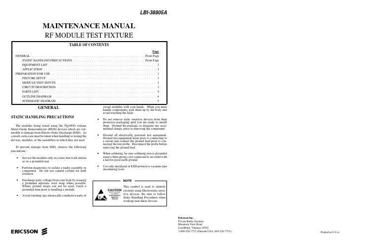
Printed in U.S.A.MAINTENANCE MANUALRF MODULE TEST FIXTUREGENERALSTATIC HANDLING PRECAUTIONSThe modules being tested using the TQ-0650 contain Metal Oxide Semiconductor (MOS) devices which are vul-nerable to damage from Electro-Static Discharge (ESD). As a result, extra care must be taken when handling or testing the devices, modules, or the assemblies in which they are used.To prevent damage from ESD, observe the following precautions:•Service the modules only at a static free work station or on a grounded mat.•Perform diagnostics to isolate a faulty assembly or component. Do not use canned coolant for fault isolation.•Discharge static voltage from your body by wearing a grounded antistatic wrist strap where possible.Where ground straps can not be used, touch a grounded item prior to handling a module.•Avoid touching any electrically conductive parts ofcircuit modules with your hands. When you must handle components, pick them up by the body and avoid touching the leads.•Do not remove static sensitive devices from their protective packaging until you are ready to install them. Ground the package, to dissipate any accu-mulated charge, prior to removing the component.•Ground all electrically powered test equipment.Ground test equipment leads prior to connecting to a circuit and connect the ground lead prior to con-necting the test probe. Disconnect the probe before removing the ground lead.•When soldering, be sure soldering iron is grounded using a three prong cord connected to an outlet with a known good earth ground.•Use only metalized or ESD protective vacuum-type desoldering tools.ericssonzEricsson Inc.Private Radio Systems Mountain View RoadLynchburg, Virginia 245021-800-528-7711 (Outside USA, 804-528-7711)LBI-38805AEQUIPMENT LISTThe following equipment is included in the Test Fixture TQ-0650, package:•RF Module Test Fixture (344A4153P1)•Wall Mount Power Supply (16.8 Vac, 770 mA) (19A705998P7)•DB25-DB25 PC Interface Cable (344A4136P1)•PC Programming Software (344A4148P1)RFTEST.EXE - executable for loadingSynthesizer ModulesRFTEST.OVL - default parameters•Instruction Manual, LBI-38805 APPLICATIONThis test fixture allows the technician to perform out of system testing on the following MASTR III RF modules:•Transmit Synthesizer, 19D902780•Receive Synthesizer, 19D902781•Rx Front End RF Module, 19D902782•IF Module, 19D902783•Power Amplifier, 19D902797PREPARATION FOR USEFIXTURE SETUP1.Plug in the Wall Mount Transformer to the AC powersource and connect the output cable to the POWER INconnector, J10, on the Text Fixture.2.When testing the Synthesizer Module, connect the PCInterface Cable between the connector labeled COM-PUTER (J11) and the Parallel Printer Port (LPT1 orLPT2) on a PC.3.To use programming software, insert the disk in the Adrive and type:A:RFTEST <Return>MODULE TEST SETUPSUse the appropriate module setup for the module under test.Refer to the applicable module maintenance manual for detailson alignment, tuning and troubleshooting.1. Load the Receive Synthesizer Module with the cor-rect frequency.2.Press "PUSH TO TUNE" and adjust the tuningcapacitor on the module to produce 6 Vdc at TP 3(TEST) or until the frequency at J2 is at the correctfrequency ±50 kHz.3. Reload the Receive Synthesizer Module with thecorrect frequency.4. Check that the red "MODULE FAULT" LED is notlit.5. Verify that the output frequency and level are correctat J2.6. Verify that the reference frequency and level arecorrect at J3.Copyright © April 1992, Ericsson GE Mobile Communications Inc.Figure 1 - Test Fixture Front PanelTransmit Synthesizer1.Set/adjust the module for the correct frequency.2.Load the Transmit Synthesizer Module with thecorrect frequency.3.Check that the red "MODULE FAULT" LED is notlit.4.Verify that the output frequency and level are correctat J2.5.Apply the modulating frequency at (MOD+,MOD-)and adjust module for the required deviationReceive SynthesizerLBI-3880511.Set the Signal Generator (or load the Receive Syn-thesizer Module) to the appropriate frequency, this frequency should correspond to the desired receive frequency, Fo ±21.4 MHz.2.Center the Spectrum Analyzer/Tracking Generator on the desired center frequency with about a 20 MHz span and set the reference level to about -30 dBm,the tracking generator output level output should be set to 0 dBm.3.Sequentially adjust the tuning slugs of L1 throughL5 to the heights specified in the Maintenance Man-ual for the desired center frequency.4.Sequentially adjust the tuning slugs of L1 through L5 to get the optimum frequency response.5.Check that the red "MODULE FAULT" LED is not lit.1.Set the Signal Generator to the correct IF and apply Standard Modulation at a level of -60 dBm.2.Adjust VR1 on the module to produce 1 Vrms at pin 7(V/S HI) on J14.3.Check that the red "MODULE FAULT" LED is not lit.RxRF Module (method 1)1.Set the Signal Generator 1 with 0 dBm output level (or load the Receive Synthesizer Module) to the appropri-ate local oscillator frequency.2.Set the Signal Generator 2 with 0 dBm output level to the corresponding receiver input frequency.3.Sequentially set L1 through L5 of the module to the heights in Table 2 of the Maintenance Manual for the desired input frequency.4Sequentially adjust L1 through L5 of the module togive the maximum output level on the RF Level Meter,then lock the tuning screws.5.Check that the red "MODULE FAULT" LED is not lit.LBI-388052To use Transmit Synthesizer as signal source:1.Load the Transmit Synthesizer Module with the cor-rect frequency.To use Signal Generator as signal source:1.Set Signal Generator to the correct frequency with anoutput level of +10 dBm.2.Set test fixture switch to "TX-ON".3.Adjust "POWER SET" for maximum.4.Adjust VR217 on the Power Amplifier board to pro-duce the maximum desired output power.5.Check that the red "PA ALARM" LED is not lit.6.Disconnect J104 from the power meter and check thatthe red "PA ALARM" LED is lit.MASTR III - BACKPLANE (RF CONNECTOR)CIRCUIT DESCRIPTIONThe RF Test Fixture (TQ0650) provides all of the regu-lated supplies required to power the RF Modules. A wallmount transformer steps down the AC line voltage to 22 Vacand connects to J10. This voltage is full-wave rectified bydiodes D1 through D4 and filtered by C27 and C29. Thefiltered output then drives a series of regulators to provide+13.8VF (actually 15 Vdc), +12 Vdc and +5 Vdc. Diodes D5and D6 rectify the AC from J10 at a negative potential to drivethe negative voltage regulator, U18 which provides -12 Vdc.The DB-25 Connector (J11) interfaces with an IBM PCCompatible Computer. U13 provides buffering and protec-tion for the computer’s parallel printer port and drives theappropriate data lines for the Synthesizer modules throughJ12.V olume/Squelch High is provided at TP6. R15 and C17de-emphasises the audio and U15 provides 6 dB of gain andbuffering to provide de-emphasised audio at TP7. U16 am-plifies the de-emphasised audio to provide about 1/2 W ofaudio drive for the speaker.An on-board frequency reference (U14) delivers suffi-cient drive for the Transmit Synthesizer "REF IN" input at afrequency of 12.8 MHz.The control voltage for the RF Power Amplifier is set byR27 and buffered with U17B to provide about 4 - 8 volts ofDC for power control. A comparator, U17A drives the "PAALARM" LED and is set to illuminate the LED when the PA"Power Sense" Output drops below 2.5 volts.A Low Pass Filter comprising L1, L2, C1 and C2 can beused to filter the IF Output from the RxRF Module to provideaccurate measurement for Front End tuning.LBI-388053PARTS LISTOUTLINE DIAGRAMPRINTED WIRING BOARD APRINTED WIRING BOARD BRF MODULE TEST FIXTURE344A4153P1ISSUE 1*COMPONENTS ADDED, DELETED OR CHANGED BY PRODUCTION CHANGESLBI-388054SCHEMATIC DIAGRAM LBI-38805PRINTED WIRING BOARD A(19C852239, Sh. 1, Rev. 0)5SCHEMATIC DIAGRAM LBI-38805PRINTED WIRING BOARD B(19C852239, Sh. 2, Rev. 0)6LBI-38805 This page intentionally left blank7。
rft中文操作指南(上)

RFT中文操作指南(上)练习 1.1:设置 Functional TestIBM 提供 Java 运行时环境(JRE),可以安装并启用它来测试 Java 应用程序。
对于本教程,您将使用该 JRE。
如果您想测试自己的 Java 或 HTML 应用程序,就必须运行启用程序并配置您的环境和应用程序。
关于这些设置任务的更多信息,请参阅欢迎页面的“第一步”页面上的“Functional Test 入门”向导。
目前您不需要采取任何措施来使用预配置的 JRE 就可以继续操作。
设置日志记录选项Functional Test 提供了几个日志记录选项。
我们将使用 HTML 日志。
1.要验证这是您设置的选项,请单击窗口 > 首选项。
2.在“首选项”对话框的左侧窗格中,展开Functional Test,然后展开回放并单击日志记录。
3.验证日志类型字段右边的使用缺省值复选框已被选中,并且html出现(变灰)在字段中。
4.单击确定。
此设置会在您回放脚本后自动打开 HTML 日志。
创建 Functional Test 项目在开始记录之前,您必须先创建 Functional Test 项目。
1.在 Functional Test 菜单中单击文件 > 新建 > Functional Test 项目。
2.在项目名称下输入FTtutorial,不要加任何空格。
3.在项目位置下输入C:\FTproject。
Functional Test 会创建这个目录。
4.如果有源控制选项可用,则不要选择将项目添加到源控制中。
5.如果有关联项目选项可用,则不要选择将 Functional Test 项目与当前 Rational 项目相关联。
6.单击完成。
现在,在 Functional Test 透视图的左侧窗格“Functiona l Test 项目”视图中可以看到FTtutorial 项目。
现在您可以开始进入练习 1.2:记录脚本。
RFT简明操作指南

1 Rational Functional Tester概述Rational Functional Tester(以下简称RFT)是一个面向对象的、自动测试工具,它使您能够测试各种应用程序。
通过录制一个应用程序的测试您可以很快产生测试脚本,您还可以测试这个应用程序之中的任何对象,包括这个对象的属性和数据。
RFT可以给您提供一个编写脚本语言的机会和两种开发环境:Eclipse 框架中的Java或Microsoft Visual Studio开发系统中的。
RFT的基础是针对于Java、.NET的对象技术和基于Web 应用程序的录制、回放功能。
当您记录脚本时,RFT会为被测的应用程序自动创建测试对象地图。
对象地图中包含了对每个对象的识别属性。
当您在对象地图中更新记录信息时,任何使用了该对象地图的脚本会共享更新的信息,减少了维护的成本及整个脚本开发的复杂度。
对象地图还为您提供快速的方法向脚本中添加对象。
它列出应用程序中涉及到的测试对象,不论它们当前是否可视。
您可以通过依据现有地图或按需添加对象来创建新的测试对象地图。
在记录过程中您可以将验证点插入到脚本中以确定在被测应用程序建立过程中对象的状态。
验证点获取对象信息(根据验证点的类型,可以是对象属性验证点或五种数据验证点之一-- 菜单层次、表格、文本、树形层次,或列表)并在基本数据文件中存储。
文件中的信息成为随后的建立过程中对象的期望状态。
在执行完测试之后,您可以使用验证点比较器(Verification Point Comparator)进行分析,并且如果对象的行为变化了就更新基线(期望的对象状态)。
在测试对象地图中,您可以观察到与列表与地图相关的脚本,且可以使用该列表来选择要添加测试对象的多个脚本。
2. 界面(工具栏)工具栏中包含这些图标:Open the New Wizard -- 显示适当的对话框来创建许多项中的一个或录制Functional Test 脚本。
RF 设备调试手册说明书
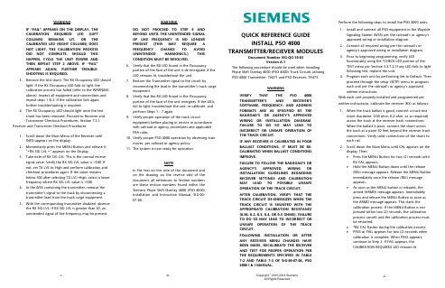
WARNINGIF “FAIL” APPEARS ON THE DISPLAY, THECALIBRATION REQUIRED LED (LEFTCOLUMN) REMAINS LIT, OR THECALIBRATED LED (RIGHT COLUMN) DOESNOT LIGHT, THE CALIBRATION PROCESSDID NOT COMPLETE. SHOULD THISHAPPEN, CYCLE THE UNIT POWER ANDTHEN REPEAT STEP 2 ABOVE. IF “FAIL”APPEARS AGAIN, FURTHER TROUBLE-SHOOTING IS REQUIRED.3.Remove the test shunt. The RX Occupancy LED shouldlight. If the RX Occupancy LED fails to light, thecalibration process has failed (refer to the WARNINGabove). Inspect all equipment and connections andrepeat steps 1 & 2. If the calibration fails again,further troubleshooting is required.4.The RX Occupancy LED should light once the testshunt has been removed. Proceed to Receiver andTransceiver Checkout Procedures, Section 7.5.1. Receiver and Transceiver Checkout Procedures1.Scroll down the Main Menu of the Receiver untilINFO appears on the display.2.Momentarily press the MENU Button and release it.“+RX SIG LVL =” appears on the Display.3.Take note of RX SIG LVL. This is the normal receivesignal value. Verify the RX SIG LVL value is >300. Ifnot, set TX LVL to High and perform calibration andcheckout procedures again. If the value remainsbelow 300 after selecting TX LVL=High, select a lowerfrequency where RX SIG LVL value is >300.4.In the WSS containing the transmitter, remove thetransmitter’s signal to the track by disconnecting atransmitter lead from the track surge equipment.5.With the corresponding transmitter disabled, observethe RX SIG LVL. If RX SIG LVL is greater than 20, anunintended signal of like frequency may be present.WARNINGDO NOT PROCEED TO STEP 6 ANDBEYOND UNTIL THE UNINTENDED SIGNALOF LIKE FREQUENCY IS NO LONGERPRESENT (THIS MAY REQUIRE AFREQUENCY CHANGE TO AVOIDUNINTENDED HARMONICS.) THISCONDITION MUST BE RESOLVED.6.Verify that the RX LED found in the Occupancyportion of the face of the unit is de-energized. If theLED remains lit, troubleshoot the unit.7.Restore the Transmitter signal to the circuit byreconnecting the lead in the transmitter’s track surgeequipment.8.Verify that the RX LED found in the Occupancyportion of the face of the unit energizes. If the LEDsfail to light, troubleshoot the unit, re-calibrate, andperform Steps 1 - 7 again.9.Verify proper operation of the track circuitequipment before placing in service in accordancewith railroad or agency procedures and applicableFRA rules.10.Verify proper PSO 4000 operation by observing trainmoves, per railroad or agency policy.11.The system is now ready for operation.NOTEIn the text on this side of the document andon the drawing on the reverse side of thedocument, all references to Section numbersare those section numbers found within theSiemens Phase Shift Overlay 4000 (PSO 4000)Installation and Instruction Manual, SIG-00-07-06.QUICK REFERENCE GUIDEINSTALL PSO 4000TRANSMITTER/RECIEVER MODULESDocument Number SIG-QG-10-03Version A.1The following procedure should be used when installingPhase Shift Overlay 4000 (PSO 4000) Track Circuits utilizingPSO 4000 Transmitter, 7A471 and PSO Receiver, 7A473.WARNINGVERIFY THAT THE PSO 4000TRANSMITTER’S AND RECEIVER’SSOFTWARE, FREQUENCY, AND ADDRESSFORMATS ARE AS SPECIFIED BY THERAILROAD’S OR AGENCY’S APPROVEDWIRING OR INSTALLATION DIAGRAM.FAILURE TO DO SO MAY LEAD TOINCORRECT OR UNSAFE OPERATION OFTHE TRACK CIRCUIT.IF ANY RECEIVER IS CALIBRATED IN POORBALLAST CONDITIONS, IT MUST BE RE-CALIBRATED WHEN BALLAST CONDITIONSIMPROVE.FAILURE TO FOLLOW THE RAILROAD’S ORAGENCY’S APPROVED WIRING ORINSTALLATION GUIDELINES REGARDINGRECEIVER SETTINGS AND CALIBRATIONMAY LEAD TO POSSIBLE UNSAFEOPERATION OF THE TRACK CIRCUIT.AFTER CALIBRATION, VERIFY THAT THETRACK CIRCUIT DE-ENERGIZES WHEN THETRACK CIRCUIT IS SHUNTED WITH THEAPPROPRIATE CALIBRATION RESISTANCE(0.06, 0.2, 0.3, 0.4, OR 0.5 OHMS). FAILURETO DO SO MAY LEAD TO INCORRECT ORUNSAFE OPERATION OF THE TRACKCIRCUIT.FOLLOWING INSTALLATION OR AFTERANY RECEIVER MENU CHANGES HAVEBEEN MADE, RECALIBRATE THE RECEIVERAND TEST FOR PROPER OPERATION PERTHE REQUIREMENTS SPECIFIED IN TABLE7-2 AND TABLE 7-3 OF SIG-00-07-06, PSO4000 I & I MANUAL.Perform the following steps to install the PSO 4000 units:1.Install and connect all PSO equipment in the WaysideSignaling Station (WSS) per the railroad’s or agency’sapproved wiring or installation diagram.2.Connect all required wiring per the railroad’s oragency’s approved wiring or installation diagram.3.Prior to beginning programming, verify LEDfunctionality using the *CHECK LED portion of theTEST menu per Section 5.2.7.2. If any LED fails to lightfollowing test, replace the unit.4.Program each unit by performing Set to Default. Thenproceed through the setup (SETP) menu to programeach unit per the railroad’s or agency’s approvedwritten instructions.With each unit properly installed and programmed perwritten instructions, calibrate the receiver (RX) as follows:1.When the track ballast is good, connect a track testshunt (hardwire, 0.06-ohm, 0.2-ohm, or as required)across the track at the receiver track connections.When the ballast is poor, connect the shunt acrossthe track at a point 30 feet beyond the receiver trackconnections. Verify solid connections of the shunt toeach rail.2.Scroll down the Main Menu until CAL appears on thedisplay. Then:•Press the MENU Button for two (2) seconds untilRX CAL appears.•Hold the MENU Button down until the release(REL) message appears. Release the MENU Buttonimmediately once the release (REL) messageappears.•As soon as the MENU button is released, thearmed (ARMD) message appears. Immediatelypress and release the MENU Button as soon asthe ARMD message appears. This starts thecalibration process. If the MENU Button is notpressed within two (2) seconds, the calibrationprocess cancels and the calibration process mustbe restarted.•*RX CAL flashes during the calibration process.•PASS or FAIL appears for two (2) seconds whencalibration is complete. When PASS appears,continue to Step 3. If FAIL appears, theCALIBRATION REQUIRED LED remains lit-2--8--7- Copyright © 2010-2014 SiemensAll Rights ReservedPSO 4000 TRANSMITTER, 7A471PSO 4000 RECEIVER, 7A473 Array-3- -4- -5- -6-。
RF测试仪说明书

Display Measurement functions : CRT displays either polar trace or Channel I and Channel 2 rectilinear traces . Reference position : independent reference lines for Channel 1 and Channel 2 and polar center can be set to any position for calibration . Video filter : typically 100 Hz (10 kHz without filter) . Graticule size : rectilinear 10 cm by 8 cm ; polar 8 cm in diameter . Smith chart overlays : 2, 1, 0 .2 and 0 .1 full scale (furnished) . CRT photography: Tektronix C-5B Oscilloscope Camera is recommend (UV illumination will not excite P39 CRT phosphor for graticule exposure) . Resolution : 10, 2 .5, 1, 0 .25 dB magnitude per major division . 90, 45, 10, 2 .5 degrees phase per major division, Accuracy : ±2% ±0 .05 division for rectilinear trace . Within 2 .5 mm for polar trace .
- 1、下载文档前请自行甄别文档内容的完整性,平台不提供额外的编辑、内容补充、找答案等附加服务。
- 2、"仅部分预览"的文档,不可在线预览部分如存在完整性等问题,可反馈申请退款(可完整预览的文档不适用该条件!)。
- 3、如文档侵犯您的权益,请联系客服反馈,我们会尽快为您处理(人工客服工作时间:9:00-18:30)。
一、配置
1、点击配置图标,输入密码:LCT;或按“Alt+Ctrl+Shift+L”键进入配置界面
2、基本配置如下图
分为:仪器控制、手机控制、手机平台、测试条件等四部分
因目前手机控制部分还没有做到兼容MTK、ADI、IFX这些平台,故测试时需要选择“手动操作”,这时的开机、拨号动作需要手动或者通过Repair工具来做;
3、功能选择
如下图
本页可配置
a)测试类型选择,如:GMSK Test、GPRS Test、EDGE Test等,三选一,不可选择
多个;
b)测试项选择:如:功率、PVT、频差、相差等;
GMSK和GPRS共用左边部分,EDGE 用右边部分
4、测试参数
如下图
本页可配置:
a)调制方式,如:GMSK调制、GPRS调制、EDGE调制等,需要与“功能选择”
页保持一致,CodeScheme和MulitSlot等(GPRS、EDGE用,不过目前EDGE
还不支持);
b)信道、功率等级配置,可手动输入,也可点击“全信道”和“全功率等级”
设置;
二、保存测试结果
a) 测试完成后,请点击如下图所示红色线框内的位置
b)然后弹出如下图所示的保存文件对话框,输入文件名即可;
c)等填充完数据后,再点击Excel中的保存按钮即可;如下图中的红色线框内所示。