西门子产品手册
西门子S7-200 SMART系统手册说明书
SIMATICS7S7-200 SMART 系统手册Siemens AGDivision Digital Factory Postfach 48 4890026 NÜRNBERG A5E03822234-AFⓅ 02/2019 本公司保留更改的权利Copyright © Siemens AG 2019. 保留所有权利法律资讯警告提示系统为了您的人身安全以及避免财产损失,必须注意本手册中的提示。
人身安全的提示用一个警告三角表示,仅与财产损失有关的提示不带警告三角。
警告提示根据危险等级由高到低如下表示。
危险表示如果不采取相应的小心措施,将会导致死亡或者严重的人身伤害。
警告表示如果不采取相应的小心措施,可能导致死亡或者严重的人身伤害。
小心表示如果不采取相应的小心措施,可能导致轻微的人身伤害。
注意表示如果不采取相应的小心措施,可能导致财产损失。
当出现多个危险等级的情况下,每次总是使用最高等级的警告提示。
如果在某个警告提示中带有警告可能导致人身伤害的警告三角,则可能在该警告提示中另外还附带有可能导致财产损失的警告。
合格的专业人员本文件所属的产品/系统只允许由符合各项工作要求的合格人员进行操作。
其操作必须遵照各自附带的文件说明,特别是其中的安全及警告提示。
由于具备相关培训及经验,合格人员可以察觉本产品/系统的风险,并避免可能的危险。
按规定使用 Siemens 产品请注意下列说明:警告 Siemens产品只允许用于目录和相关技术文件中规定的使用情况。
如果要使用其他公司的产品和组件,必须得到 Siemens推荐和允许。
正确的运输、储存、组装、装配、安装、调试、操作和维护是产品安全、正常运行的前提。
必须保证允许的环境条件。
必须注意相关文件中的提示。
商标所有带有标记符号 ® 的都是 Siemens AG的注册商标。
本印刷品中的其他符号可能是一些其他商标。
若第三方出于自身目的使用这些商标,将侵害其所有者的权利。
西门子操作手册

1安装2电气系统原理与性能 (1)3调试 (2)4操作注意事项 (3)5警告与安全 (3)安全表示可能危害人身安全的警示。
表示可能引起设备事故的注意事项。
警口本产品在安装前必须详细阅读本产品说明书,及相关产品说明书,了解说明书的内容后方可操作设备,否则会有设备及人身事故隐患。
只有合格的人员才可从事相应的工作。
合格人员是指熟悉设备安装,调试及保养的并且有相应资格从事其工作人员。
设备安装及接线过程不可通电。
设备必须按国际标准可靠接地,以保证运行安全可靠。
注意事项设备安装前,不得露天放置,地面应干燥,如设备受潮应做干燥处理。
用户连接电源线及电机时必须注意导线与接线端子之间要紧固。
热继电器应按说明书中的整定值或对应电机的额定电流值设定,不得随意调整,否则起不到保护电机的作用。
1 安装1.1设备组成本机由烘燥箱体,循环风机,排风机,电加热系统及其他控制系统组成1.2 设备供电电源本设备电源采用:AC380V 3 © 50HZ设备装机容量约为:20KW1.3电气设备安装机上电器安装请参见电气安装图1.4电气设备接线警告:电气设备外壳必须按国际标准可靠接地。
电气设备接线参照互连接线图2 电气系统原理与性能2.1变频器该设备选用的是西门子的MMV44系列变频器,这种变频器均由微处理器控制,并采用具有现代先进技术水平的绝缘栅双极型晶体管(IGBT)作为功率输出器件。
因此具有很高的运行可靠性和功能的多样性。
具有优良的速度稳定性和动态响应特性。
具有快速电流限制功能,具有较完善的保护和故障诊断功能。
2.2S7-200 可编程序控制器PLC选用S7-200可编程序控制器。
S7-200是德国西门子公司生产的模块化中小型PLC系统,客观满足中等性能要求的应用,大范围的各种功能模块,可以非常好地满足和适应自动化控制任务,由于简单实用的分散式结构和多界面网络能力,使得应用十分灵活,当控制任务增加时,可自由扩展,由于大范围的集成功能使得它功能非常强劲。
西门子 SITRANS P DS III 系列压力变送器 产品手册
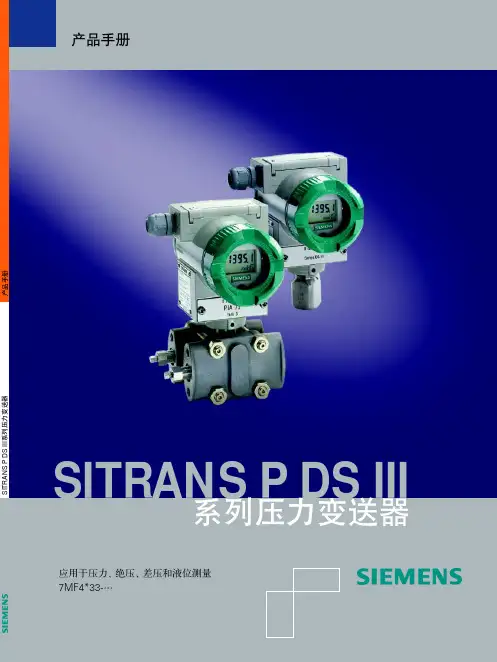
SITRANS P DS III
!"#$
!
SITRANS P!"#$ DS III
!"# 7MF4*33!"#$
Sห้องสมุดไป่ตู้MATIC®,SIPART®,SIREC®,SITRANS® 为西门子注册商标。 所有其他产品名称和系统名称的注册商标所有权必须得到遵守。
未经授权,严禁复制、传播和使用本手册内容。版权所有,违者责任自负。 更新的技术数据内容手册中无注明。
1.2
2
系统说明 ................................................................................................................................................. 2-1 2.1 2.2
7MF4□33 系列 SITRANS P - DS III 压力/差压变送器
DS III 系列变送器,差压系列包括差压、流量、液位和绝压测量,压力系列包括压力、绝压测量。 产品手册
目录
目录
1 技术说明 ................................................................................................................................................. 1-1 1.1 应用范围 ........................................................................................................................................1-1 1.1.1 压力 .................................................................................................................................1-2 1.1.2 差压和流量 ......................................................................................................................1-2 1.1.3 液位 .................................................................................................................................1-2 1.1.4 绝压 .................................................................................................................................1-2 设计和工作原理 .............................................................................................................................1-2 1.2.1 设计 .................................................................................................................................1-3 1.2.2 工作方式..........................................................................................................................1-5 1.2.2.1 电路原理 .........................................................................................................1-5 1.2.2.2 压力测量 .........................................................................................................1-6 1.2.2.3 差压和流量测量 ..............................................................................................1-6 1.2.2.4 液位测量 .........................................................................................................1-7 1.2.2.5 差压系列中的绝压测量 ...................................................................................1-7 1.2.2.6 压力系列中的绝压测量 ...................................................................................1-8 系统组成 ........................................................................................................................................2-1 SIMATIC PDM...............................................................................................................................2-2
西门子产品宣传手册PPT

公司荣誉
企业辉煌成就
您的内容打在这里或者通过复制您的文本后在此框中选择 粘贴并选择只保留文字。
最佳先进科技企业荣誉称号 最佳先进科技企业荣誉称号 最佳先进科技企业荣誉称号 最佳先进科技企业荣誉称号
公司荣誉
公司自建立以来,十分注重自身素质的提高。近年来公司在市场准入以及资质认证方面都取得了突破 性的进展。我公司最近取得的资质证书包括:
Your Logo
2020
公司介绍
适用于 创业计划/策划方案/商业规划/工作汇报/商业路演
目录
CONTENTS
1 公司简介 2 公司团队 3 企业荣誉 4 产品介绍
01
公司简介
公司介绍
旗下分支机构
在此录入图表的描述说明, 在此录入图表的描述说明。
企业简介
右键点击图片选择设置图片格式可直接 替换图片。您可以点击文字框输入您的描述 说明,或者通过复制粘贴,在此录入您的描 述说明。在此录入上述图表的综合描述说明, 在此录入上述图表的综合描述说明,在此录 入上述图表的综合描述说明。
组织架构
合作伙伴
董事长 总经理
法务部
市 品 采 财综 场 质 购 务合 部 部 部 部部 制
造 中 心
研发部门 研 究 室
市场营销部 广销 售 告售 后 部部 部
03
企业荣誉
公司荣誉
✓ 某某企业荣誉证书 ✓ 某某企业先进企业荣誉证书 ✓ 某某企业创新事业积极进取荣誉证书
您的内容打在这里,或者通过复制您的文本后,在此框中选择粘贴,并选择 只保留文字。您的内容打在这里,或者通过复制您的文本后。
拥有员工数量
在此录入图表的描述说明, 在此录入图表的描述说明。
产品总销售额
西门子-CP 114 – CP 115 差压变送器 产品手册说明书
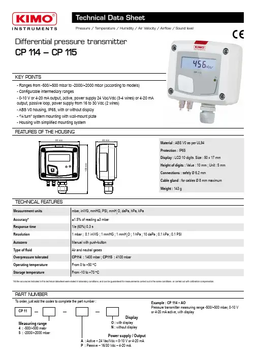
Differential pressure transmitterCP 114 – CP 115KEY POINTSMaterial : ABS V0 as per UL94Protection : IP65Display : LCD 10 digits. Size : 50 x 17 mmHeight of digits : Value : 10 mm ; Unit : 5 mm Connections : safety Ø 6.2 mmCable gland : for cables Ø 8 mm maximum Weight : 143 g- Ranges from -500/+500 mbar to -2000/+2000 mbar (according to models)- Configurable intermediary ranges- 0-10 V or 4-20 mA output, active, power supply 24 Vac/Vdc (3-4 wires) or 4-20 mA output, passive loop, power supply from 16 to 30 Vdc (2 wires)- ABS V0 housing, IP65, with or without display - “¼ turn” system mounting with wall-mount plate - Housing with simplified mounting systemFEA TURES OF THE HOUSING90 mm109 m m46 mmTECHNICAL FEA TURESMeasurement units mbar, inWG, mmHG, PSI, mmH 2O, daPa, hPa, kPa Accuracy*±1.5% of reading ±3 mbar Response time 1/e (63%) 0.3 sResolution 1 mbar ; 0.1 inWG ; 1 mmHG ; 1 mmH 2O ; 1 hPa ; 10 daPa ; 0.1 kPa ; 0.1 PSI Autozero Manual with push-button Type of fluidAir and neutral gasesOverpressure tolerated CP114 : 1400 mbar ; CP115 : 4100 mbar Operating temperature From 0 to +50 °C Storage temperatureFrom -10 to +70 °CMeasuring range4 : -500/+500 mabr5 : -2000/+2000 mbarPART NUMBERCP 11To order, just add the codes to complete the part number :Power supply / OutputA : Active – 24 Vac/Vdc – 0-10 V or 4-20 mA P : Passive – 16/30 Vdc – 4-20 mADisplayO : with display N : without displayExample : CP 114 – AOPressure transmitter measuring range -500/+500 mbar, 0-10 V or 4-20 mA active, with display*All the accuracies indicated in this technical datasheet were stated in laboratory conditions, and can be guaranteed for measurements carried out in the same conditions, or carried out with calibration compensation.TECHNICAL SPECIFICA TIONSCONNECTIQUESPressure connectionsOutput / Supply- active sensor 0-10 V or 4-20 mA (alim. 24 Vac/Vdc ± 10%), 3-4 wires - passive loop 4-20 mA (power supply 16/30 Vdc), 2 wires - maximum load : 500 Ohms (4-20 mA)- minimum load : 1 K Ohms (0-10 V)Consumption2 VA (0-10 V) or max. 22 mA (4-20 mA)Electromagnetical compatibility EN61326Electrical connection Screw terminal block for cables Ø0.05 to 2.5 mm 2 Communication to PC Kimo USB-mini Din cable EnvironmentAir and neutral gasesInside the front housingDIP SwitchsOutput terminalblockPower supply terminalblockLCC-S connectionFixed back housingRemovable front faceCable glandAutozeroELECTRICAL CONNECTIONS – as per NFC15-100 standardThis connection must be made by a qualified technician . To make the connection, the transmitter must not be energized.For CP114/115 – AO models and CP114/115 – ANmodels with 0-10 V or 4-20 mA output – active, 4 wires:A-+0-10 V output76LN Power supply 24 Vac class IIor N L12+3VP +5IP4GND -7+6-Power supply 24 Vdc-VRegulator display orPLC/BMS passive typeor-+4 wiresTo make a 3-wire connection, before powering up the transmitter, please connect the output ground to the input ground. See drawing below.4 wires3 wires+4-20 mA outputRegulator display orPLC/BMS active type-12+3VP +5IP4GND -7+6-3 wiresPower supply24 Vdc+5IP4GND -7L 6N +Power supply24 Vac class IILN A-+0-10 V outputor VRegulator display or PLC/BMS passive type-+Sortie 4-20 mARegulator display or PLC/BMSactive type orSETTINGS AND USE OF THE TRANSMITTERTo perform an autozero, unplug the 2 pressure connections tubes and press the “Autozero” key.When an autozero has been performed, “On” green light turns off then turns on, and on transmitters equipped with a display, “autoZ” is displayed.➢ Autozero➢ ConfigurationTo configure the transmitter, it must not be energized. Then, you can make the settings required, with the DIP switches (as shown on thedrawing below). When the transmitter is configured, you can power it up.To configure the transmitter, unscrew the 4screws from the housing then open it. DIPswitches allowing the different settings arethen accessible.To set a measuring range, put the 1, 2 and 3 on-off switches as indicated in the table below.➢ Measuring range settings – left DIP switchExample :● From 0 to 750 mmH2O, measuring range is 750 mmH2O.● From -500 mbar to +500 mbar, measuring range is 1000 mbar.● Measuring ranges of the CP114transmitter on the ±500 mbar range according to the measurement unit.● Measuring ranges of the CP115transmitter on the ±2000 mbar range according to the measurement unit.Type oftransmitterCP114CP115CP114CP115CP114CP115CP114CP115CP114CP115 mbar100500200750300100040015005002000inWG40.0200.080.0300.0120.0400.0160.0600.0200.00800.0 kPa10.050.020.075.030.0100.040.0150.050.0200.0 PSI 2.010.0 4.015.0 6.020.08.030.010.040.0 mmHg8040016060024080032012004001600mmH2O1000500020007500300010 000400015 000500020000 daPa 1.0 5.0 2.07.5 3.010.0 4.015.0 5.020.0 hPa100500200750300100040015005002000 12341234123412341234Combination 1Combination 2Combination 3Combination 4Combination 5Measuringranges settingStandard range orcentral 0 settingLeft DIP switch12341234Right DIP switchOutput settingUnits settingOn-off switch➢ Standard range / central zero setting – left DIP switchTo set the type of measuring range, put the on-off switch 4 as indicated beside :Configurations Full scale Central zeroCombinationsExample 0-100 mbar : Full scale / 0Central zero(0 / 100 mbar)(-50 mbar / 0 / +50 mbar)For CP114/115 – PO models and CP114/115 – PN models with 4-20 mA output – passive :2 wires IT57+6-Power supply16-30 VdcVdcA-+IT57+6-Vdc-2 wires+A2 wires............Display/regulator/PLCpassive typeDisplay/regulator/PLCactive type +-16-30 VdcorF T a n g – t r a n s m i t t e r _C P 114-115 – 08/03/13 – R C S (24) P ér i g u e u x 349 282 095 N o n -c o n t r a c t u a l d o c u m e n t – W e r e s e r v e t h e r i g h t t o m o d i f y t h e c h a r a c t e r i s t i c s o f o u r p r o d u c t s w i t h o u t p r i o r n o t i c e .MAINTENANCEPlease avoid any aggressive solvent. Please protect the transmitter and its probes from any cleaning product containing formalin, that may be used for cleaning rooms or ducts.OPTIONS AND ACCESSORIES●KIAL-100A : Power supply class 2 , 230 Vac input, 24 Vac output●LCC-S : configuration software with USB cable●Connection tube ●Connection fittings ●Through-connections●Straight connections ●Spherical coupling nut➢Output setting – right DIP switch (CP114/115 – AO and CP114/115 – AN models)To set the type of analogue output, please put the on-off switch of the output as shown beside.➢Units setting – right DIP switchTo set a measurement unit, put the on-off switches 2, 3 and 4 of the units as shown in the table below.Please follow carefully the combinations beside with the DIP switch. If the combination is wrongly done, the following message will appear on the display of the transmitter “CONF ERROR”. In that case, you will have to unplug the transmitter, place the DIP switches correctly, and then power the transmitter up.ConfigurationsmbarinWGkPaPSImmHGmmH 2OdaPahPaCombinationsConfigurations4-20 mA0-10 VCombinations1234123412341234123412341234123412341234MOUNTINGTo mount the transmitter, mount the ABS plate on the wall (drilling : Ø6 mm, screws and pins are supplied).Insert the transmitter on the fixing plate (see A on the drawing beside). Rotate the housing in clockwise direction until you hear a “click” which confirms that the transmitter is correctly installed.Once the transmitter is installed and powered up, please make an autozero to guarantee the correct working of the transmitter in any position.An easy and friendly configuration with the software !You can configure your own intermediary ranges.Caution : the minimum difference between the high range and the low range is 20.For example, it is possible to set the instrument from -20 to 0 mbar, from 0 to +20 mbar, or from -10 to +10 mbar...• To access the configuration via software :- Set the DIP switches as shown beside. Nota : the on-off switch 1 of the right DIP switch can be inany position (selection of the analogue output 0-10 V or 4-20 mA)- Connect the cable of the LCC-S to the connection of the transmitter.• Please refer to the user manual of the LCC 100 to make the configuration.CONFIGURA TION VIA LCC-S SOFTW ARE (option)1234Left DIP switch 1234Right DIP switchThe configuration of the parameters can be done either with the DIP switch or via software (you can not combine both solutions).7.5mm8mm4.5mm40mm50m m68m m75mm37.5mm23.75m m14mmAA。
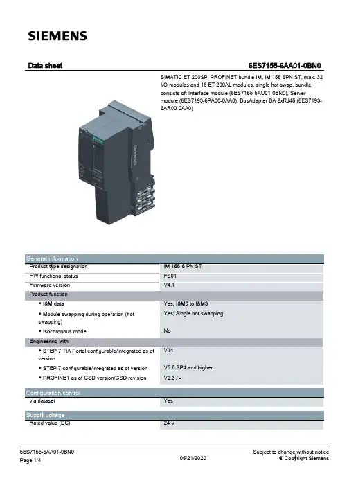
西门子Simatic ET 200SP产品说明书
Input current Current consumption (rated value) Current consumption, max. Inrush current, max. I²t
Power Infeed power to the backplane bus
0 °C 60 °C 0 °C 50 °C 5 000 m; Restrictions for installation altitudes > 2 000 m, see manual
Yes; + 16 ET 200AL modules
50 mm 117 mm 74 mm
190 g; IM 155-6 PN BA with 2x RJ45 ports and server module 05/13/2020
Power loss Power loss, typ.
Address area Address space per module ● Address space per module, max. Address space per station ● Address space per station, max.
IM 155-6 PN ST FS01 V4.1
Yes; I&M0 to I&M3 Yes; Single hot swapping
No
V14
V5.5 SP4 and higher V2.3 / -
Configuration control
via dataset
Yes
Supply voltage
Rated value (DC)
西门子自控产品样本说明书
2100RTN…STS61… VEN…AVN15-12SSA…STA…VPD…AVN15A16Product Range OverviewSmall Valves, Actuators + Accessoriesfor radiator, floor heating and chilled ceiling applicationsSelf-contained thermostatic actuators RTN… without auxiliary power•CEN-certified and tested to DIN EN215 part 1•Absolute noiseless actuator technology• Long service life•Manual setpoint adjustment, min. and max. limitationFavorably priced thermal actuators STA…, STS61… for demanding requirements•Absolute noiseless actuator technology• Long service lifeElectromotoric actuators SSA… for the most demanding requirements•Automatic detection of valve stroke• Long service life• Low noise•Plug-in connecting cableRF-controlled actuator SSA955 for radiator valves•For integration into the Siemens Synco 900 systemPreadjustable radiator valves VDN…, VEN…, VUN…•CEN-certified and tested to DIN EN215 part 1•Insert can be replaced while plant is under pressurePressure compensated radiator valves VPD…, VPE… (MCV) for perfect hydraulicbalancing• Solves noise problems•No line balancing valves required•No hydraulic balancing required because of automatic pressure compensation•Creates comfort and saves energyVarious mounting accessories•Simple and fast mounting•High operation safety.CE1N2100enBuilding TechnologiesEquipment combinations: Thermostatic and electronic actuators, valves and fittings2/63/6Accessories For mounting• thermostatic actuators RTN… • electromotoric actuators SSA… • RF-controlled actuator SSA955 • thermal actuators STA… • thermal actuators STS61…on radiator valves of other manufacturer according to table:Notes1) Oventrop has been using M30 x 1.5since 2001, requiring no adapter 2) Not to be used with RTN...3) TA (Heimeier) has been using M30 x1.5 since 2003, requiring no adapterConnection (M30 x 1.5) on valves of other manufacture, without adapter • Heimeier • Junkers• Honeywell Braukmann • MNG• Cazzaniga• Oventrop M30 x 1.5 (as of 2001) • TA-Type TBV-C • Beulco newThe sealing insert is suited for use with all radiator valves of the ranges VPD… and VPE….Adapter (AV…)Differential pressure overflow valves VS9…Sealing insert AV100-VP14/6Type reference (alphabetical)Type reference DescriptionG [in]DesignData sheetADN10 3/8ADN15 1/2ADN20 3/4straight AEN10 3/8 AEN15 1/2AEN20Lockshield valve 3/4angle N2107ATN1 Partner clip ATN2 Removal protection ATN3 Manual knob ATN4 Manual knob AVN1 Valve insertAVN10-12 3/8 Tube ∅ 12 mmAVN15-12 1/2 Tube ∅ 12 mmAVN15-14 1/2 Tube ∅ 14 mm AVN15-15 1/2 Tube ∅ 15 mmAVN15-16 Fittings for copper and steel pipes 1/2 Tube ∅ 16 mm AVN15P12 1/2 Tube ∅ 12 x 1.1 mmAVN15P14 Fittings for Pex plastic tubing 1/2 Tube ∅ 14 x 2 mm AVN15A14 1/2 Tube ∅ 14 x 2 mmAVN15A16 Fittings for Alupex tubing 1/2 Tube ∅ 16 x 2 mm AV51…AV61Adapter for valves of other manufacture N2100 RTN51… Thermostatic actuatorRAL 9016white glossy appearanceRTN71 Thermostatic actuator with remote sensor RTN81 Thermostatic actuator with remote adjusterN2111SSA31… Electromotoric actuator AC 230 V SSA81… Electromotoric actuator AC 24 V SSA61… Electromotoric actuator AC / DC 24 V N4893 SSA955 RF-controlled actuator SSA955 Battery-powered (LR6 / AA) N2700 STA21… Thermal actuator AC 230 V STA71… Thermal actuator AC / DC 24 V N4877 STA72E… Thermal actuator AC / DC 24 V N4875 STS61…Thermal actuatorAC 24 VN4880 VDN110 3/8VDN115 1/2VDN120 3/4straight, DIN N2105 VDN210 3/8 VDN215 1/2VDN220Valve3/4straight, NF N2106 VEN110 3/8VEN115 1/2VEN120 3/4angle, DIN N2105 VEN210 3/8VEN215 1/2VEN220 3/4angle, NF VUN210 3/8 VUN215 Valve1/2 reverse angle, NFN21065/6VDN10M 3/8VDN15M 1/2VDN20M 3/4straight VEN10M 3/8 VEN15M 1/2VEN20M Manual valve 3/4 angle N2104VPD110A-45 VPD110A-90 VPD110A-145 3/8VPD115A-45 VPD115A-90 VPD115A-145 1/2VPD110B-60 VPD110B-120 VPD110B-200 3/8VPD115B-60 VPD115B-120 VPD115B-200 1/2straight, DINVPE110A-45 VPE110A-90 VPE110A-145 3/8VPE115A-45 VPE115A-90 VPE115A-145 1/2VPE110B-60 VPE110B-120 VPE110B-200 3/8VPE115B-60 VPE115B-120 VPE115B-200 Mini-Combi-Valve (MCV)1/2angle, DINN2185VPD210A-45 VPD210A-90 VPD210A-145 3/8VPD215A-45 VPD215A-90 VPD215A-145 1/2VPD210B-60 VPD210B-120 VPD210B-200 3/8VPD215B-60 VPD215B-120 VPD215B-200 1/2straight, NFVPE210A-45 VPE210A-90 VPE210A-145 3/8VPE215A-45 VPE215A-90 VPE215A-145 1/2VPE210B-60 VPE210B-120 VPE210B-200 3/8VPE215B-60 VPE215B-120 VPE215B-200 Mini-Combi-Valve (MCV)1/2angle, NFN21856/6VS920 3/4VS932 Differential pressure overflow valve1 1/4VS920F 3/4 VS932FDifferential pressure overflow valve for district heating house substations1 1/4angle N2181Technical notes NO valves• fully open when de-energized (normally open). • Valve stem extended.Radiator valves like VDN…, VEN…, VUN…, VPD… or VPE… are usually NO valves.NC valves• Closed when de-energized (normally closed). • Valve stem extended.Small valves like V…P47… are usually NC valves.NO function • Actuator stem is retracted when de-energized. • Valve is open.NC function• Actuator stem is extended when de-energized. • Valve is closed.The thermostatic RTN… actuators control the heat demand. They control the water flow by opening and closing the radiator valves.• With increased heat demand the actuator stem retracts and steadily opens the radia-tor valve.• With decreasing heat demand the actuator stem extends and steadily closes the radiator valve.STA…Radiator valves (NO valves) actuator de-energized • VDN…, VEN…, VUN… • VPD…, VPE…closed (NC function)Use STA72E actuators for DESIGO RX…The STS61… thermal actuator is driven by a DC 0...10 V positioning signal. The actua-tor can be operated in two directions of actions (Y or Y ) and can therefore be used with radiator NO valves as well as with small valves NC.OperationBreakdownDirection of action DC 0…10 V Actuator stem Valve behavior Actuator de-energizedY increasing Stem retracts NO opens NO radiator valve or MCV closedY increasing Stem extends NC opens NC small valves openThe electromotoric the actuator is driven by DC 0…10 V positioning signal or by a 3-position signal. The description of operation in this document applies to the valve versions which are fully open when de-energized (NO). • Voltage at Y1: Stem retracts Valve opens • Voltage at Y2:Stem extends Valve closes • No voltage at Y1 and Y2:Actuator maintains its current position• The valve opens / closes in proportion to the control signal at Y. • At DC 0 V, the valve is fully closed (A Æ AB), stem extended• When power supply is removed, the actuator maintains its current position.NO, NC valvesValve and actuator combinationsRTN…STA…, STP…AttentionSTS61…SSA31…, SSA81…3-Position control signalDC 0...10 V©2006 - 2008 Siemens Switzerland Ltd Subject to alteration。
西门子SIMATIC S7-1200 CPU 1212C 产品说明书
General information Product type designation Engineering with ● Programming package
Supply voltage Rated value (DC) ● 24 V DC permissible range, lower limit (DC) permissible range, upper limit (DC) Load voltage L+ ● Rated value (DC) ● permissible range, lower limit (DC) ● permissible range, upper limit (DC)
CPU processing times for bit operations, typ. for word operations, typ. for floating point arithmetic, typ.
CPU-blocks Number of blocks (total)
OB ● Number, max.
Encoder supply 24 V encoder supply ● 24 V
Power loss Power loss, typ.
Memory Work memory ● integrated ● expandable Load memory ● integrated ● Plug-in (SIMATIC Memory Card), max. Backup ● present ● without battery
6 4; 100 kHz Pulse Train Output No; to be provided externally L+ (-48 V)
西门子 3WN6 万能式断路器 框架式断路器 (ACB) 产品手册
3WN6 万能式断路器
新型的 3WN6 系列万能式断路器适用于额定电流从630~3200A ,运行电压至AC690V 的大型建筑物、工矿企业、电站和水厂等场所,还适用于钴井机或船舶等场合。
3WN6 的优点:
• 紧凑的外形使其可用于体积更小的开关柜• 固定式和抽屉式• 热耗散减少• 满负载运行至 55°C • 所需的控制功率减少• 多种功能特征
• 标准型中配置有多种可视信号和电气信号• 模块化结构
• 适合于各种用途的过电流保护单元
应用
3WN6 系列断路器可应用于:• 在三相系统中作为进线和出线装置
•用于通断和保护电动机、发电机、变压器和电容器组
• 作为大型设备的主开关
用途广泛的新型过电流脱扣器
新型的 3WN6 断路器以拥有新一代的过电流脱扣器为特征。
所有的过电流脱扣器可用作时间分段控制,并且具有状态显示和故障原因显示。
脱扣信号独立存储而不需外部电源,信号的查询也不需附加的信号装置。
对于脱扣器机电参数配置的测试也包含在脱扣器中。
根据用户需要,还可以提供扩展的报警功能,电流表甚至通讯模块。
功能可用于能量管理,或诊断数据输,以及准确地预测维修周期。
s
框架式断路器 (ACB)。
西门子操作手册
目录1 安装 (1)2 电气系统原理与性能 (1)3 调试 (2)4 操作注意事项 (3)5 警告与安全 (3)安全表示可能危害人身安全的警示。
表示可能引起设备事故的注意事项。
警告本产品在安装前必须详细阅读本产品说明书,及相关产品说明书,了解说明书的内容后方可操作设备,否则会有设备及人身事故隐患。
只有合格的人员才可从事相应的工作。
合格人员是指熟悉设备安装,调试及保养的并且有相应资格从事其工作人员。
设备安装及接线过程不可通电。
设备必须按国际标准可靠接地,以保证运行安全可靠。
注意事项设备安装前,不得露天放置,地面应干燥,如设备受潮应做干燥处理。
用户连接电源线及电机时必须注意导线与接线端子之间要紧固。
热继电器应按说明书中的整定值或对应电机的额定电流值设定,不得随意调整,否则起不到保护电机的作用。
1 安装1.1 设备组成本机由烘燥箱体,循环风机,排风机,电加热系统及其他控制系统组成。
1.2 设备供电电源本设备电源采用: AC380V 3φ 50HZ设备装机容量约为:20KW1.3 电气设备安装机上电器安装请参见电气安装图1.4 电气设备接线警告:电气设备外壳必须按国际标准可靠接地。
电气设备接线参照互连接线图2电气系统原理与性能2.1 变频器该设备选用的是西门子的MMV440系列变频器,这种变频器均由微处理器控制,并采用具有现代先进技术水平的绝缘栅双极型晶体管(IGBT)作为功率输出器件。
因此具有很高的运行可靠性和功能的多样性。
具有优良的速度稳定性和动态响应特性。
具有快速电流限制功能,具有较完善的保护和故障诊断功能。
2.2S7-200可编程序控制器PLC选用S7-200可编程序控制器。
S7-200是德国西门子公司生产的模块化中小型PLC系统,客观满足中等性能要求的应用,大范围的各种功能模块,可以非常好地满足和适应自动化控制任务,由于简单实用的分散式结构和多界面网络能力,使得应用十分灵活,当控制任务增加时,可自由扩展,由于大范围的集成功能使得它功能非常强劲。