联轴器的安装、操作和维护保养说明
十字轴式万向联轴器的安装与维护

十字轴式万向联轴器的安装与维护一、十字万向联轴器安装时,首先应按图纸要求,检测法兰盘栓孔的分布误差、止口及端面联接尺寸的误差和万向联轴器的同轴度误差,还要注意分布置方位和原始相位,联轴器两端原则上都可作主动轴,但注意花键配合处尽量远离振源或冲击源为宜。
螺栓和螺母等紧固件应符合机械性能等级要求,紧固螺母时南在螺纹处可稍注入些粘合剂,在带负荷运转一个班后,再检查螺栓是否松动,并以标准预防紧力矩再次拧紧,如此重复两个班以防松动。
二、万向联轴器轴承和花键副要进行定期润滑,一般采用2号工业锂基脂,但在高温情况下宜用3号或4号钙基脂也可用4号合成锂基脂,前三个月内每月注油一次,工作条件稳定后,每间隔三个月注油一次,高温条件下每周注油一次。
万向联轴器应定期进行维护保养,一般在运行半年后进行维修,其具体时间视使用条件而定,当运行时发现有异常声响、振动、发生漏油等不正常情况,应立即停机检查,及时处理。
维修时应仔细检查零部件,十字轴和轴承的滚动面是否有剥落、点蚀、磨损及压痕,压痕大于0.25mm应予更换,垫片磨损量超过0.35mm也应更换。
轴承和十字轴不能在清洗其它零件的同一油盘内清洗,洗清后应用压缩空气吹干,清洗时不允许用汽油和钢丝刷。
三、组装时,按拆卸时的相反顺序进行,应注意花键轴和花键套两相位相同;装配十字轴总成时应调整好垫片以保证十字轴中心线与叉头中心线的同轴公差。
其偏移量小于0.05-0.1mm,规格越小取小值,同时使每一轴端与垫片间的间隙保持在0.06-0.12mm以内,以防过大的轴间窜动。
四、为了增加万向联轴器的使用寿命,每次拆卸时将十字轴调整180度以使十字轴轴颈交替使用。
大型机器设备调整两轴对中较困难,应选择使用耐久和更换易损件方便的联轴器。
金属弹性元性挠性联轴器一般比非金属弹性元件挠性联轴器的使用寿命长。
需密封润滑和使用不耐久的联轴器,必然增加维护工作量。
对于长期连续运转和经济效益较高的场合,例如我国冶金企业的轧机传动系统高速端,目前普遍采用的是齿式联轴器,齿式联轴器虽然理论上传递转矩大,但必须在润滑和密封良好的条件下才能耐久工作。
联轴器安装基本要求

联轴器安装基本要求联轴器安装基本要求在减速机的安装过程中为了保证减速机的有效性,一定要正确的安装减速机,禁止锤击、正确的添加润滑油等等,减速机的联轴器安装一般是采取热装的形式。
1、热装联轴器(1)做好联轴器的热装准备,需要使用汽油或者煤油清洗轴颈和联轴器的配合处; (2)查看部件是否有粗糙、损伤问题,如果有损伤则需要采取措施消除,(3)测量轴颈和联轴器内径及键槽尺寸,如果部件尺寸不符,则需要进行修配,保证联轴器可以正常的热装。
(4)联轴器热装时,需将温度加热至250℃左右,在升温时温度不能升的过快,否则会影响联轴器温度均匀性。
当加热到指定温度后,测量加热后的膨胀数值,以测量联轴器膨胀后的内径,然后将加热膨胀的内径数值最大量棍放入联轴器内径孔,进行热套工作,就完成了减速机联轴器的热装工作。
2、热装时需要注意的具体事项(1)核对联轴器是否与另外一个相联结的联轴器成对,将相对应的联轴器安装在减速机上。
(2)检查联轴器配合面的完好性,查看其表面是否存在毛刺、擦伤等缺陷。
(3)加热过程中如果用样杆测量孔径数值时,应该停止加热操作。
(4)热装完成后,应使用冷水对轴颈使其冷却,保障减速机的整体功能。
一、联轴器安装操作工序设备试车设备清洗出库检验 2 1联轴器装配联轴器找正3645二、安装过程控制要求1.准备序号工作内容检查项目技术要求操作要领检测器具1.1 施工交底执行体系文件1.2 设备检查和验收联轴器尺寸检查执行《设备检查和验收》游标卡尺、千分尺轴直径尺寸、键槽的尺寸、键的尺寸执行《设备检查和验收》游标卡尺、千分尺1.3 联轴器内孔表面清洗、修理内孔表面的光洁度表面光洁、无毛刺、无变形用砂纸、钢锉、破布、清洗油等进行处理1.4 轴表面清洗、修理轴表面表面光洁、无毛刺、无变形用砂纸、钢锉、破布、清洗油等进行处理1.5 键的清洗、修理键到角用砂纸、钢锉、破布、清洗油等进行处理序号工作内容检查项目技术要求操作要领检测器具2.1 联轴器装配冷装配合公差轴径≤孔径利用轴端的攻丝孔和长杆丝杠,或另做的马鞍架,采用千斤顶将联轴器压入,联轴器装配前,应在联轴器内孔和转轴上抹上润滑油。
常用联轴器安装与使用
常用联轴器安装与使用联轴器是传动装置中常用的一种元件,用于连接两个轴,并传递转矩和旋转运动。
常见的联轴器类型有齿式联轴器、弹性联轴器、万向联轴器等。
下面将介绍常见联轴器的安装与使用方法。
1.齿式联轴器的安装与使用:齿式联轴器适用于正反转运动、较高转速和大转矩传递的场合。
其安装步骤如下:(1)安装轴承、轴封和油封,并检查轴的直径和轴孔直径是否符合要求。
(2)清洗联轴器和轴孔,并涂上适当的润滑油。
(3)将联轴器两个部分置于联轴器的两个轴上,并检查各部分之间的插入是否正确。
(4)旋紧联轴器上的螺丝或螺纹销,并使用扭矩扳手进行适当的拧紧。
(5)启动设备,观察联轴器的运行情况,如有异常应及时停止检查。
2.弹性联轴器的安装与使用:弹性联轴器适用于传递较小转矩和较高转速的场合,并能吸收轴间的角偏差和轴向错位。
其安装步骤如下:(1)将联轴器两个部分分别套在两个轴上,然后将两个轴对准联轴器的中心线。
(2)使用特制工具或锤子小心地将联轴器两端的套筒推入联轴器的相应孔中。
(3)检查联轴器的拧紧螺栓,并按照规定的扭矩值进行拧紧。
(4)启动设备,并观察联轴器的运行情况,如有异常应及时停止检查。
3.万向联轴器的安装与使用:万向联轴器适用于需要传递不同角度和方向旋转运动的场合。
其安装步骤如下:(1)检查联轴器的轴孔和轴的直径,确保其符合要求。
(2)将联轴器两个部分按照正确的角度安装在两个轴上,并使用通心销或螺栓进行固定。
(3)启动设备,并观察联轴器的运行情况,如有异常应及时停止检查。
在使用联轴器时,还需注意以下几点:(1)定期检查联轴器的磨损程度,如有磨损需要及时更换。
(2)定期加注润滑油,保持联轴器的良好润滑状态。
(3)避免超负荷使用联轴器,防止其损坏或产生故障。
(4)注意防尘和防锈措施,确保联轴器的正常运行。
联轴器设备安全操作规定
联轴器设备安全操作规定为确保联轴器设备的安全运行,保障员工身体健康和企业的安全生产,制定本操作规定。
一、设备安装1.安装联轴器设备时,必须严格按照相关设备安装要求进行操作。
2.安装联轴器设备时,必须确保设备稳定、坚固,不得出现松动和变形现象。
3.安装联轴器设备时,必须注意设备的垂直度和水平度,确保安装位置准确无误。
二、设备维护1.定期对联轴器设备进行检查,如发现问题及时通知设备维护人员进行维护和修理。
2.在使用过程中,发现联轴器设备有异常声音、震动、过热等现象时,应及时停机检查原因,并进行维修。
3.定期润滑润滑部位,并注意检查润滑系统的工作情况。
三、设备操作1.调整设备时,必须切断设备电源,并确认已安全停止,才可进行操作。
2.在设备运行时,禁止对设备进行任何非调整及操作动作。
3.在设备机件运转时,禁止手、头部、衣物等靠近运动部位。
4.不得在设备操作时离开岗位,出现设备故障时应及时通知维修人员。
四、事故处理1.在联轴器设备使用过程中,如出现设备故障,应立即停止设备使用,避免事故发生。
2.在设备操作过程中,如出现人员伤害等情况,立即停止设备并进行相关应急处理和事故报告。
3.发生设备损坏或事故,相关责任人应及时进行事故调查和对设备进行维护和修复。
五、安全培训1.企业必须定期进行联轴器设备安全操作规定培训,确保员工掌握安全操作知识。
2.新工人上岗前,企业必须进行联轴器设备安全操作规定培训,并经过考核合格后方可上岗。
以上操作规定为联轴器设备安全操作的最基本要求,在使用联轴器设备时,还需注意其他使用安全、电气安全、周边环境安全等要点。
企业对联轴器设备的安全运行,需从安全操作培训、设备保养维修和安全监测等方面全面保障,确保设备安全运行,保障员工身体健康。
型弹性柱销联轴器安全操作及保养规程
型弹性柱销联轴器安全操作及保养规程前言型弹性柱销联轴器广泛应用于机械传动中,具有安装简便、使用灵活、传动效率高等特点。
但是如果操作不当或者缺少保养,会给设备安全带来隐患。
为了确保设备的安全性和性能,制定操作及保养规程,对运行中的机械设备进行维护和管理,既能延长设备的使用寿命,同时也能提高工作效率。
安全操作规程1.在使用前认真检查型弹性柱销联轴器的连接件是否松动以及变形等情况,对于问题开裂或者变形非常严重的联轴器,必须立即更换。
2.在拆卸联轴器时,需先切断机器电源,切勿在拆卸联轴器时启动电机,以免发生意外。
3.严禁将联轴器承载力超过其额定承载力,否则会因为超负荷而导致联轴器破坏。
4.当设备运行时,切勿随意冲击联轴器,以免造成不必要的破坏。
5.在使用中,切勿将联轴器涂上油或油脂等润滑油,以防止其出现胶化或变形等问题。
6.在使用后,应将联轴器表面和各部位清洗干净,以便检查联轴器的损坏和磨损情况。
保养规程1.在未使用之前,应将型弹性柱销联轴器存放在干燥、通风、无酸碱气体和不受阳光照射的地方,以防止储后、变形等情况的发生。
2.运行时,应对联轴器进行常态气压检查,并进行必要的调整保养。
3.联轴器在使用一段时间后,应检查其表面是否起皮等情况,在检查后应及时对其表面进行处理或更换。
4.定期对联轴器进行检测,检查联轴器机身是否受损,表面是否有裂纹或破损,零部件是否松动等问题,并进行必要的调整、修复或更换。
5.长期离线,需对联轴器内、外表面进行防锈防尘处理,以保证下次使用时联轴器性能不受影响。
6.联轴器在长时间运转后,应注意检查其轴承是否异常,如果存在异响等情况,需立即停机进行检修,为避免不必要的事故。
结语制定型弹性柱销联轴器安全操作及保养规程,为机械传动设备的使用和维护提供了基本的标准和认识,符合规程的使用、保养能够有效地提高机械设备的使用效率,并延长设备的使用寿命。
希望在今后的生产实践中认真贯彻规程,更好地维护和管理我们的机械设备。
约翰克雷恩TSCS-T型柔性盘式联轴器安装、操作与维护说明书

TSCSInstallation, Operation & Maintenance Instructions1These instructions are provided to familiarize the user with John Crane's Metastream TSCS coupling and its designated use. These instructions must be followed whenever work is carried out on the coupling and should be kept available for future reference.ATTENTION These instructions are for the fitting, operationand maintenance of the coupling as used inrotating equipment and will help to avoid dangerand increase reliability. The information requiredmay change with other types of equipment orinstallation arrangements. These instructionsmust be read in conjunction with the instructionmanuals for both the driver and driven machinery.If the coupling is to be used for an application other than that originally intended or outside the recommended performance limits, John Crane must be contacted before its installation and use.Any warranty may be affected by improper handling, installation or use of this coupling. Contact John Crane for information as to exclusive product warranty and limitations of liability.If questions or problems arise, contact your local John Crane sales/ service engineer or the original equipment manufacturer as appropriate. ATTENTION John Crane couplings are precision products and mustbe handled appropriately. Take particular care to avoiddamage to spigots, mating faces, hub bores, keyways andmembranes. Do not excessively compress the couplingmembranes during assembly. Refer to Table 2 forcompression limits (min gap ‘X’).These instructions are written for standard catalog products, generally designed in accordance with the drawing shown.1– Transmission unit2– Standard hub - external location (sizes 0014-1400) 2A– Disc hub (large bore) (option on sizes 0014-0360) 2B– Long hub (option on sizes 0120-1400)3– Hub bolt 4– Guard ring5–S pacer6– Disc pack7– D rive bolt assembly (drive bolt, locknut, sleeve [washer] and overload collar)FIGURE 1TSCSInstallation, Operation & Maintenance InstructionsThese instructions are provided to familiarize the user with John Crane's Metastream TSCS coupling and its designated use. These instructions must be followed whenever work is carried out on the coupling and should be kept available for future reference.ATTENTION These instructions are for the fitting, operationand maintenance of the coupling as used inrotating equipment and will help to avoid dangerand increase reliability. The information requiredmay change with other types of equipment orinstallation arrangements. These instructionsmust be read in conjunction with the instructionmanuals for both the driver and driven machinery.If the coupling is to be used for an application other than that originally intended or outside the recommended performance limits, John Crane must be contacted before its installation and use.Any warranty may be affected by improper handling, installation or use of this coupling. Contact John Crane for information as to exclusive product warranty and limitations of liability.If questions or problems arise, contact your local John Crane sales/ service engineer or the original equipment manufacturer as appropriate. ATTENTION John Crane couplings are precision products and mustbe handled appropriately. Take particular care to avoiddamage to spigots, mating faces, hub bores, keyways andmembranes. Do not excessively compress the couplingmembranes during assembly. Refer to Table 2 forcompression limits (min gap ‘X’).These instructions are written for standard catalog products, generally designed in accordance with the drawing shown.FIGURE 11– Transmission unit2– Standard hub - external location (sizes 0014-1400) 2A– Disc hub (large bore) (option on sizes 0014-0360) 2B– Long hub (option on sizes 0120-1400)3– Hub bolt 4– Guard ring5– S pacer6– Disc pack7– D rive bolt assembly (drive bolt, locknut, sleeve [washer] and overload collar)2 34 5672B2AThe following designations are used in the installation instructions to highlight instructions of particular importance.IMPORTANT is used for items of particular concern when using the coupling.ATTENTION where there is an obligation or prohibition concerning the avoidance of risk.where there is an obligation or prohibition concerning harm to people or damage to the equipment.The usual extent of supply comprises:• A factory-assembled transmission unit (1) comprising:–2-off guard rings (4)–1-off spacer (5)–2-off disc packs (6)–12-off drive bolt assemblies (7) *consisting of drive bolt and nut, overload collar and washer*• Driver hub (2, 2a, 2b)• Driven hub (2, 2a, 2b)• 2 sets of hub bolts (3) to secure the transmission unit between the two hub flanges• A set of compression bolts to compress the transmission unit for assembly between the hubsNOTE: Only supplied with 0360 size, or for all sizes when both sides have a disc hubs–For TDCS-0014 and TSCS-0025 to 0215, with at least one standard hub, compress using standard hub bolts (half on each side).–For TSCS-0350 to 1400 sizes, compress using compression slots in the hub. If the length of the spacer allows it, it may be possible to use the standard hub bolts to compressIMPORTANT If a general arrangement drawing is supplied with the coupling, then all data indicated on that drawing takes precedence over information included in these instructions.If the coupling is not to be used immediately, it should be stored indoors or in a waterproof container away from direct heat in its original packing. All documentation supplied with the coupling should be retained for future reference.If the coupling has an extended hub which is designated by**** - **** - **E* - **** on a transmission unit**** - **** - **C* - **** or**** - **** - **D* - **** on a complete couplingplease refer to IOM supplement IOM 021 for additional spares and installation information.When requesting spares, always quote the full designation of the coupling (e.g., TSCS-0120-0177-1500).The following spares can be purchased from John Crane:• Set of hub bolts (3) *please specify standard,long and/or disc hubs*• Hubs, bored to your requirement or unbored (2, 2a, 2b)• Complete transmission unit, balanced or unbalanced (1)• ‘A-kit’ disc fixings including:–Drive bolt assembly (7)• ‘B-kit’ disc pack:–disc pack (6)• ‘C-Kit’ disc pack and fixings:–Disc pack (6)–Drive bolt assembly (7)• ‘O-Kit’ Guard ring assembly:–Disc pack (6)–Drive bolt assembly (7)–Guard ring (4)Remove the coupling from the packaging and carefully inspect for signs of damage. Pay particular attention to the hub bores and the spigot/recess location features, which should be free from burrs and other damage.Installation of hubsPrior to installing the coupling, ensure that themachinery is made safe. Hubs must be adequatelysupported during installation to avoid accidentaldamage should they slip.Installation gapsThere is a “minimum” and “preferred” installation gap that is required behind the disc hub (see Table 1).• The “minimum” installation gap (see Figure 2) is mandatory andis required to allow the transmission unit to be fitted and removed without moving driving or driven machinery. However, the small gapParallel bore with keyed drive1. Ensure the hub bore and mating shaft are clean.2. The hub is usually installed with the hub face and shaft end flush.3. Measure the shaft diameter and hub bore to confirm the correct fit.4. For clearance fits, install the key(s) into the shaft keyway and, witha little lubrication on the shaft, slide the hub onto the shaft. The keyshould be a tight sliding fit in the keyway with a small clearance at the top of the key. Secure the hub to the shaft in the correct axialposition with one or more grub screws.5. John Crane recommends a light interference fit for most applicationsand it may be necessary to apply heat to assist fitting of such hubs.A warm oil bath will usually be adequate. DO NOT spot heat orexceed 175°C (347°F) as this may cause distortion. A thermal heat stick can be used to estimate the temperature before quickly sliding the hub onto the shaft. A suitable stop will ensure the correct axial position is located.FIGURE 24Installation, Operation & Maintenance InstructionsIMPORTANT DBSE should be measured between the inner face of the hubs and should not be taken as the length of thetransmission unit at its outer periphery. DBSE may notbe equal to the precise distance between shaft ends.In particular, the faces of taper bored hubs may not beflush with the shaft end (refer to Figure 6).4. Align the shaft center lines both horizontally and vertically, ideallyusing the shafts. However, if access prohibits this, then align using the hub bosses or flanges. John Crane recommends the reverse peripherymethod for accurate alignment. This can be done using dial gauges orwith a laser shaft alignment kit. Further details on recommended laseralignment vendors are available from John Crane on request.5. Recheck the DBSE after the shafts have been aligned.6. Axial shims (together with a shim carrier in some cases) may besupplied on applications where it is difficult to accurately set apredetermined shaft end separation (DBSE). This is often the casewhere one or both of the hubs are taper bored. Where this feature is supplied, the thickness of shims (plus carrier if applicable) are added to the free length of the transmission unit so that the combined length is equal to the measured distance between the hub flange faces,making any allowance for known shaft movements.NOTE: It is best to measure the transmission unit when it is in a gagged condition.IMPORTANT The misalignment tolerances quoted in literature and on drawings allow for dynamic conditions and variations. For the best service from the coupling, John Crane recommends that installed misalignment is no morethan 10% of the maximum allowable misalignment, with allowance being made for any anticipated movements that will occur during operation (e.g., thermal movements on hot pumps).1. Check spigot and recess locations on the hubs and transmission unit for damage. The transmission unit must be adequately supported during installation to avoid accidental damage should it slip.2. Compress the transmission unit while sliding it between the hubs. –For the TDCS-0014 and TSCS-0025 to 0215, compress using hub bolts (3). –For the TSCS-0360 (standard and disc hub) or for all sizes if disc hubs are present on both sides, separate compression bolts willalways be supplied.–For TSCS-0350 to 1400, compress using compression slots in the hub flanges. If the length of the spacer allows it, it may be possible to use the hub bolts to assist with compression. To allow for compression using hub bolts (3), the spacer flanges (5) are drilled to allow the bolts to be threaded into the guard ring (4) as shown in Figure 7. For DBFF’s less than the preferred minimum, spacer flanges are slotted. Tightening evenly, compressing the transmission unit until clearance between the hub spigots and transmission unit length isachieved, allowing installation. Do not over compress the transmission unit as this can damage the metal disc elements. The minimum gap ‘X’ (see Figure 7) should not be less than the values shown in Table 2, unless indicated otherwise on the general arrangement drawing.IMPORTANT Always remove the compression bolts as soon as thetransmission unit is in position.3. Align the hub/transmission unit flanges if they have been match marked.4. Initially fit hub bolts loosely by hand. Tighten these evenly to locate the transmission unit, ensuring the spigots enter their recessessquarely. Using a torque wrench, tighten in a "diametrically opposite" sequence to the torque values shown in Table 2 (tightening torque relates to lubricated bolts).5. Measure dimension 'A' (see Figure 1) on the transmission unit. Check against the nominal value given in Table 2 with a tolerance of +/-0.006 inch. If outside these limits, redo the axial alignment.6. Rotate the machinery two or three times slowly to ensure it moves freely.FIGURE 6FIGURE 7TSCSInstallation, Operation & Maintenance InstructionsThe transmission unit must be adequately supportedduring installation to avoid accidental damage should it slip.2. Compress the transmission unit while sliding it between the hubs.–For the TDCS-0014 and TSCS-0025 to 0215, compress using hub bolts (3).–For the TSCS-0360 (standard and disc hub) or for all sizes if dischubs are present on both sides, separate compression bolts will always be supplied. –For TSCS-0350 to 1400, compress using compression slots in the hub flanges. If the length of the spacer allows it, it may be possible to use the hub bolts to assist with compression. To allow for compression using hub bolts (3), the spacer flanges (5) are drilled to allow the bolts to be threaded into the guard ring (4) as shownin Figure 7. For DBFF’s less than the preferred minimum, spacer flanges are slotted. Tightening evenly, compressing the transmission unit until clearance between the hub spigots and transmission unit length is achieved, allowing installation. Do not over compress the transmission unit as this can damage the metal disc elements. The minimum gap ‘X’ (see Figure 7) should not be less than the values shown in Table 2,unless indicated otherwise on the general arrangement drawing.IMPORTANT Always remove the compression bolts as soon as the transmission unit is in position.3. Align the hub/transmission unit flanges if they have been match marked. 4. Initially fit hub bolts loosely by hand. Tighten these evenly to locate the transmission unit, ensuring the spigots enter their recesses squarely. Using a torque wrench, tighten in a "diametrically opposite" sequence to the torque values shown in Table 2 (tightening torque relates to lubricated bolts).5. Measure dimension 'A' (see Figure 1) on the transmission unit. Checkagainst the nominal value given in Table 2 with a tolerance of+/-0.006 inch. If outside these limits, redo the axial alignment.6. Rotate the machinery two or three times slowly to ensure it moves freely.Installation, Operation & Maintenance InstructionsOperation, Inspection and MaintenanceBefore starting the machinery, ensure that allnecessary safety procedures are being observedand coupling guards are fitted.Routine examination should include a periodic check on the tightness of fasteners and visual inspection of transmission unit components for signs of fatigue or wear.If the coupled machinery is disturbed at any time, shaft alignment should be rechecked. Alignment checking is recommended if a deterioration of installation alignment during service is suspected.Maintenance work must only be carried out by suitablyqualified personnel when the equipment is stationaryand has been made safe.John Crane Metastream flexible power transmission couplings are designed and selected to give an unlimited service if used within the parameters for which they are specified. Failures are rare and can generally be attributed to excessive misalignment, severe overload or a combination of both. In all cases of coupling failure, it is advisable that the cause of failure is first identified and corrected.Failure of the coupling will generally be failure of a membrane assembly.Transmission Unit RefurbishmentIt is possible to repair the coupling by fitting replacement membrane unit assemblies or replacing the entire transmission unit.To replace the transmission unit, remove the hub bolts and then withdraw the transmission unit using the compression bolts feature in the spacer, as appropriate.The transmission unit must be adequatelysupported during removal to avoid accidentaldamage should it slip.ATTENTION When repairing John Crane Metastream™ flexiblemembrane couplings, only John Crane-approved partsshould be used.NOTE: For balanced TSC spacer couplings, the transmission unit is usually supplied as a factory-assembled unit which should not be dismantled. However, when used at low or medium speeds, the transmission unit can be reconditioned, but will require rebalancing.Guard ring assembly units (O-kits), as well as B and C-kits, should bereplaced in pairs; failure of one will usually result in damage to the other.7A, B and C-kit Replacement1. Remove the guard ring assembly unit (O-kit) as per instruction 1 above.2. Remove the remaining drive nuts (8N) in order to remove the guard ringfrom the disc pack assembly.3. Assemble the relevant spares kit into the configuration as shownin Figure 8 so that the membranes and fixings are connected to theguard ring and the washers are in the correct orientation. Apply thread-locking compound (e.g., Loctite 242 or equivalent) on bolt threads whenassembling the nuts (8N) and torque to the values shown in Table 3.4. Follow instructions 3 to 5 from Guard Ring Assembly Unit (O-kit)replacement above to complete the replacement.This section refers to couplings that bear the CE and ATEX required markings:All couplings that comply with CE and ATEX legislation will be marked as shown. This will be etched on the spacer element of the transmission unit if enough room is available.A) Ambient temperature is standard (40ºC max)Where John Crane's Metastream metal membrane couplings are required for use in higher ambient temperatures, John Crane UK Ltd certifies that the equipment complies with the temperature classification range listed below in Table 1, and in all other respects complies with the type certificates.B) Ambient temperature is (-55°C < Ta < 150ºC) OR ambient temperature is unspecified, the equipment is not suitablefor mining applications, Group I, Category 2.C) Ambient temperature is (-55°C < Ta < 90ºC)When the ambient temp. is specified, ‘T3’ is replaced by the following ‘T’ mark (**) according to Table 1.NOTE:‘XX’ is the year of manufacture and will change. For example, for year 2016; XX = 16.CE and EX marks must meet requirements of Annex II in Reg. (EC) No. 765/2008 and Annex II in Dir. 84/47/EEC respectively.Operation in aggressive atmospheresThe following components contain non-metallic materials. Confirm compatibility or provide suitable protection if the coupling is to operate in an aggressive atmosphere.• The hub electrical insulation (if supplied option) – reinforced thermosetting plastic• Limited end float bearings (if supplied option) – PTFE based plasticTemperature classification of John Crane's Metastream couplingsJohn Crane's Metastream metal membrane couplings, supplied in conformance with Directive 2014/34/EU, have to meet the classifications specified in Table 1 when used in accordance with instructions and information supplied.T, L and H series couplings, using the disk type flexible elements, are covered by type examination certificate Sira 02ATEX9403.M series couplings, using the diaphragm type flexible elements, are covered by type examination certificate S ira 02ATEX9404.S. Pennington(Engineering Manager - Couplings)S. PenningtonIf the products featured will be used in a potentially dangerous and/or hazardous process, your John Crane representative should be consulted prior to their selection and use. In the interest of continuous development, John Crane Companies reserve the right to alter designs and specifications without prior notice. It is dangerous to smoke while handling products made from PTFE. Old and new PTFE products must not be incinerated. ISO 9001 and ISO14001 Certified, details available on request.©2020 John Crane JC402 Revised 03/20 IOM 016-A ENUnited States of AmericaTel: 1-847-967-2400 Fax: 1-847-967-3915United Kingdom Tel: 44-1753-224000 Fax: 44-1753-224224Brazil Tel: 55-11-3371-2500 Fax: 55-11-3371-2599United Arab Emirates Tel: 971-481-27800 Fax: 971-488-62830Singapore Tel: 65-6518-1800 Fax: 65-6518-1803。
如何安装链条联轴器
如何安装链条联轴器?记住这5个步骤
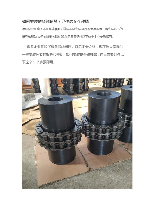
很多企业采购了链条联轴器回去以后不会安装,现在给大家提供一些安装环节的指导和帮助,如何安装链条联轴器,你只需要记住以下这个5个步骤即可.
很多企业采购了链条联轴器回去以后不会安装,现在给大家提供一些安装环节的指导和帮助,如何安装链条联轴器,你只需要记住以下这个5个步骤即可。
链条联轴器的5个安装步骤:
1、用量具测量轴和孔的尺寸,轴和孔是过盈配合,一般轴要比孔大15-20丝。
2、轴和孔要用砂纸打磨光亮,不能有铁锈,轴的键槽朝上并安装好键,涂上黄油等待安装。
3、用火焰或専用加热器对联轴器进行均匀加热至200度(根据安装情况,温度可以适当增加),加热完毕,用専用夹具夹持(小心烫伤)安装于轴上,蕞好一次到位,用铜棒或软物衬垫进行敲击到位。
4、电动机和风机联轴器之间需留3-5毫米间隙,链条联轴器然后校正两联轴器上下、左右水平及间隙。
5、电机试完转向后,将销子穿好,防护罩盖好,就可以运行了
以上就是安装链条联轴器的5个步骤,其实安装链条联轴器并不麻烦,只需要把其中第3步的加热环节把控好,还有在安装过程中不能使用锤子直接敲击联轴器,需要用铜棒或其他东西垫一下。
双膜片联轴器安全操作及保养规程

双膜片联轴器安全操作及保养规程引言双膜片联轴器是一种广泛应用于机械传动系统中的传动装置。
它能够连接两个轴,传递轴向和径向力,并具有一定的轴向、角位移补偿能力。
在使用双膜片联轴器时,需要注意一定的安全操作和保养规程,以确保设备的正常运行和延长设备寿命。
本文将介绍双膜片联轴器的安全操作和保养规程,以帮助用户正确使用和保养设备。
安全操作规程1. 选择合适的联轴器型号在选择双膜片联轴器型号时,需要考虑传动的功率、转速、轴向和角位移等因素,并根据需要选择合适的联轴器型号、材质和尺寸。
如果不确定选择何种型号,建议向生产厂家咨询。
2. 安装前检查在安装前,应先检查联轴器的轴承、联轴器叶片、保护罩等部件是否完好无损,有无划痕或磨损。
如发现不良情况,应及时更换或维修。
在安装联轴器时,需要将轴承和联轴器叶片对中,保证轴线在同一轴线上;并将联轴器叶片装在连接轴的轴向端面上,以保证联轴器的刚性和可靠性。
如发现叶片装错或装反,请立即更换。
4. 防止过载在使用双膜片联轴器时,需要防止过载。
当传动过程中出现过载时,应及时停机并检查原因,排除故障后再重新启动。
5. 防止铁磁性物质进入在使用过程中,应防止铁磁性物质进入联轴器内部,避免产生卡死情况。
如发现联轴器内部有异物,请立即停机检查。
6. 正确停机在联轴器工作时,应先将被连接的设备停止运转,然后再关闭联轴器的电源或切断输电线路。
保养规程1. 周期性检查需要周期性对联轴器进行检查,包括联轴器的叶片、轴承、保护罩等部件是否完整无损,以及联轴器的刚性、准确性等参数是否有所下降。
联轴器在工作过程中需要进行润滑,以保证轴承工作的正常。
润滑油的选择和使用应符合联轴器的要求,并按照规定周期进行更换。
3. 防止硬物冲击在使用联轴器过程中,应注意防止硬物撞击联轴器,避免影响联轴器的使用寿命和安全。
4. 正确存储如有需要暂时停止使用联轴器,需要进行正确的存储,将联轴器储存于防尘、防潮、避光、避振动的地方,避免损坏。
- 1、下载文档前请自行甄别文档内容的完整性,平台不提供额外的编辑、内容补充、找答案等附加服务。
- 2、"仅部分预览"的文档,不可在线预览部分如存在完整性等问题,可反馈申请退款(可完整预览的文档不适用该条件!)。
- 3、如文档侵犯您的权益,请联系客服反馈,我们会尽快为您处理(人工客服工作时间:9:00-18:30)。
以下的标记是在使用此安装说明书时特别需要注意的地方 重要 使用于在使用连轴器时特别需要注意的条款 注意 使用于有责任和义务避免风险的时候
数据单件号 I-TSKS ENG 0405 (PN 78257) 共7页 第2页
使用于有可能对人或仪器有伤害的时候
一个已装配的传动组包括两个防护圈(5),一个中间段(6), 两套膜片组(7)以及螺栓及配件(8) 传动轮箍 从动轮箍 两组螺栓(3)以连接传动组与轮箍法兰。
锥形轮箍孔与健驱动 1. 将轮箍安装到无键的轴上。轻轻的将轮箍打到轴上,请用个软面的锤
子以避免金属接触。 2. 用深度测量仪测量轴头到轮箍面的距离。 3. 固定一个钟面量表在轮箍内部的法兰上并调零 4. 如有必要移除轮箍,将键紧密地安装到键槽中, 键顶端留有小的间
隙。 5. 重新安装轮箍并将轴拖到仪表所指示的正确轴向位置。为达成要求的
在安装过程中必须注意充分的支撑传动组以确保避免滑落导致意外的损伤。
2. 可能需要压缩传动组来将它划动到轮箍间。轮箍法兰上提供杠杆 槽中以便安装。此外,中间段的法兰钻有孔以允许轮箍螺栓(注 释 3 )的璇入防护圈 。均匀的扭紧螺栓以压缩传动组,直至实 现轮箍栓和传动组长度之间的空间,从而使安装容易。 (见图 5 ) 。除非另设计图说明,X 的最小值应该不小于表 1 中的值。
Metastream is a registered trademark of John Crane
METASTREAMTM TSKS 连轴器 联轴器的安装、操作和维护保养说明
数据单件号 I-TSKS ENG 0405 (PN 78257) 共7页 第3页
安装说明
将连轴器从包装中拿出并仔细观察受损的迹象。特别注意轮箍的孔和安装特征部分应该避免任何毛 刺和损伤。
重要 如果连轴器有设计图提供的话, 一切以设计图上信息为优先, 包括此说明
储存
如果不是即刻需要用到此连轴器, 请保持原有包装并远离直接接触热源
保留所有与连轴器一起提供的单据以便日后需要。
备件
当需要任何备件的时候, 请提供整体的连轴器号
以下备件可以从约翰克兰购买
轮箍螺栓组(4)(请告知标准或加大轮箍) 轮箍 (按要求钻孔或不加工) 整体的传动组,平衡或未平衡(I) 膜片组包括传动组装好的螺栓和保护圈 (5,7,8)
轮箍面定位孔要按照较大的安装,每 mm 定位直径最大不能超过 0.00008mm, 或者 0.012TIR。
接头 如果机器有在轴上自带法兰, 可以将法兰加工成适合与传动组连接的构造。或者用同连轴器定作 的法兰。 参考 GA 图来做安装定位。
轴对中
按照以下方式对其传动和被动机轴中线: 1. 将机器移动到位 2. 在开始对中前检查机器 3 足情况 3. 将一个机器稳固定位, 按照图纸将轴间距设定好 重要 DBSE(轴间距)需要在轮箍内面测量而不是测量传动组的长度,因为传动组安装在外围
Metastream is a registered trademark of John Crane
METASTREAMTM TSKS 连轴器 联轴器的安装、操作和维护保养说明
传动组的安装说明
1. 检查轮箍止口和定位孔和传动组没有损伤
数据单件号 I-TSKS ENG 0405 (PN 78257) 共7页 第5页
在注油前将轴向锤或水压螺母安全的安装在部件之间
5. 在部件间注油直到达到要求的安装压力,或者到油从接触面溢出。
Metastream is a registered trademark of John Crane
METASTREAMTM TSKS 连轴器 联轴器的安装、操作和维护保养说明
6. 依靠安装工具,将轮箍移到正确的轴向位置,在这个过程中注油。 7. 释放油压。 8. 移除安装工具和注油仪器 9. 如有需要,在轴头安装锁定垫圈和螺母
个轮箍都是锥形的时候。如果有提供垫片的时候,垫片的厚度要加入在传动组中的, 这样长 度的和才等于轮箍面之间的距离。
重要
对中的公差在文件和图纸中有提供, 允许动态和其他变化。为了连轴器最好的状态下工 作,约翰克兰推荐允许不超过 10%的不对中,其中要包括运行中可能出现的情况。(如 热 的泵中的热量的变化)
键槽以及膜片的损伤。不要在安装时过多挤压连轴器膜片。安装时压力请查阅表 1。(X) 此说明是对应标准连轴器的,一般的设计与上图一致。
Metastream is a registered trademark of John Crane
METASTREAMTM TSKS 连轴器 联轴器的安装、操作和维护保养说明
如果连轴器需要被安装在与预期不同的应用上,或者超过了推荐的运行极限,请务必在安装使用前 与约翰克兰联系。
不适当的操作, 安装或者使用连轴器都有可能影响到保修。请联系约翰克兰询问特定产品保修及 局限性的信息
如有任何问题请于约翰克兰服务工程师联系, 如果需要,请联系原始设备制造商。
注意 约翰克兰的连轴器是精明的产品,必须正确操作。 特别小心避免对拴,配合面,轮箍孔,
用在已润滑的螺纹上锁紧轮毂螺栓的扭力
表1
联轴器大 轮毂螺栓 轮毂螺栓锁 最小距离 联轴器最大轴 尺寸 A (最 尺寸 A (最
小
号
紧扭力 Nm X mm 向位移 +/- mm 小)mm 大)mm
0013
M6
13
7.1
1.0
7.7
7.8
0033
M8
25
7.2
1.25
8.2
8.4
0075
M8
25
7.6
1.5
注意:对于平衡的 TSK 中间段联轴器,传动组通常以是工厂组装单位提供的,不应予以拆除。然 而,当在低或中速系统中使用时, 传动组是可以翻新的,但将需要重新平衡。 替换膜片时应该同时替换两边,因为一边膜片的失效会对另外的膜片组有损害。
置换膜片组 移除驱动螺栓( 8B 条)和螺母( 8N ) ,并从中间段中移除 膜片组装( 6 ) ,不要尝试进一步拆膜片组装。将垫圈( 8S 线)从中间段的孔中推出。
当维修约翰克兰Metastream TM膜片联轴器时,只有约翰克兰核准部件可以做替换使用。
Metastream is a registered trademark of John Crane
METASTREAMTM TSKS 连轴器 联轴器的安装、操作和维护保养说明
传动组维修翻新
数据单件号 I-TSKS ENG 0405 (PN 78257) 共7页 第7页
前言
此说明旨在帮助用户熟悉连轴器的设计用途。 在任何要使用连轴器的时候请务必阅读及实施此说 明,并且保留作将来的参考
注意 此说明是为如何安装,操作和维护保养用在旋转设备中的联轴器所做,同时也避免危险和
增加运行可靠性。 有些信息可能需要改变其他设备的安装。 请仔细阅读此说明的同时也 要注意驱动机和被驱动机的指南。
只有适当的合格人员才能进行维修工作, 并确保设备是安全固定的。
联轴器失效是罕见的,一般都可以归因于过度不对中和/或严重扭力超载。在所有情况下的联轴器 失效,应查明原因并替换联轴器。 联轴器维修可以为替换膜片组或替换整个传动组。 以取代传动组,移除轮箍螺栓然后适当的使用压缩螺栓的功能压缩传动组。 传动组必须有足够的支持,以避免在运输过程中意外滑动导致损坏。
轮箍安装说明
在安装连轴器之前, 确保机器的安全。在安装过程中必须注意充分的支撑轮箍以确保避 免滑落导致意外的损伤。
确保轮箍孔和对应的轴清洁。
直轴与健驱动 轮箍通常是与轮箍面和轴端一起安装的。 测量轴径也轮箍孔以确定正确安装 对于间隙配合, 对轴加一点润滑, 将键先装入轴的键槽内,然后滑动轮箍到轴上。 键应是紧密 配合在键槽中,与键的顶端有小的间隙。用一个或多个顶丝来确保轮箍和轴的轴向位置。 约翰克兰推荐在大部分应用中使用过盈配合,有可能需要加热来达成这种轮箍安装。可以通过热油 的浸泡可以达到要求。不要用点热源或者加热超过 175 摄氏度,这样会造成变形。一个棒状温度计 可以在迅速的安装轮箍到轴上时大致的测量温度。一个适合的挡板可以确保正确的轴向定位。 确保轮箍孔和对应的轴清洁。
M12
86
13.4
5.0
17.4
17.8
转速小于等于 3600rpm 时最大角度偏移=0.5 度;小于等于 7500rpm 时最大角度偏移=0.33 度;
大于 7500rpm 时最大角度偏移=0.25 度
Metastream is a registered trademark of John Crane
在正确的适用范围内,Metastream 动力传输联轴器是为您设计和选择来提供无限的服务。失败 是罕见的,一般都可以归因于过大的不对中度,严重超载,或两者兼有。在所有的联轴器失效的情 况下,尽快确定和纠正失败的原因。 失败的联轴器一般情况下都是由膜片组失败造成的。除了一些特殊的和大的联轴器外, 膜片组是 不能被修复,并应予以更换。
重要 请在传动组到位后,在锁紧轮箍螺栓之前,尽快移除压缩螺栓。
3. 如果轮箍/传动组法兰有同样的记号, 清将其对中。 4. 装入轮箍螺栓并均匀锁紧以定位传动组。 确保止口垂直进入定位孔。 使用润滑油润滑螺纹,
并以表 1 中对应的扭力锁紧轮拴。 5. 测量传动组中 A 的尺寸(见图 1)。 比对检查表 1 中的最小和最大值。 6. 缓慢的转动机器两三次以确保机器自由转动
METASTREAMTM TSKS 连轴器 联轴器的安装、操作和维护保养说明
数据单件号 I-TSKS ENG 0405 (PN 78257) 共7页 第1页
标号 1 2 2A 2B 3
说明 传动组 标准轮箍-外部位置 标准轮箍-内部位置 大轮箍 轮箍螺栓
标号 5 7 8 6
说明 防护圈 膜片组 传动螺栓集合 中间段
替换第二套膜片组来完成整修传动组。