
2、PLC编址方案分析
EM222(8O)×2 EM232(2AO)×1 EM222(8O)×1 EM235(4AI1AO)×2 山东铝业职业学院电气系
硬件组态方案示例
2.4 I/O地址分配与外部接线
2.4.2 S7-200的外部接线
图2-14 交流电源系统的外部接线
图2-15 直流电源系统的外部接线
山东铝业职业学院电气系
知识点2: PLC的地址分配与编址方法
2.4 I/O地址分配与外部接线 2.4.2 S7-200的外部接线
图2-16 感性输出电路的处理
山东铝业职业学院电气系
山东铝业职业学院电气系
知识点2: PLC的地址分配与编址方法
■数字量扩展模块
数字量 I/O : 8DI 、 16DI 、 4DO 、 8DO 、 4/4 、 8/8 、 16/16 、 32/32DI/DO。 输入有24V DC和230V AC两种,输出有24V DC和继电器型。
■模拟量扩展模块与热电偶热电阻扩展模块
3、CPU为扩展模块所能提供的最大电流和每种扩展模 块消耗的电流。
■在一个控制系统中,所有扩展模块消耗的电流不能超过CPU所
能提供的电流
山东铝业职业学院电气系
I/O模块编址举例:
注意:模拟
量扩展模块 是以两个字 的方式来分 配地址空间
山东铝业职业学院电气系
扩展模块电流值的计算:
山东铝业职业学院电气系
EM221(8I)×2 EM231(4AI)×2 EM221(8I)×1 EM223(4I4O)×1
知识点2: PLC的地址分配与编址方法
限制最大I/O配置的因素
1、各CPU的主机I/O和可连接的最多扩展模块数。
■扩展模块的数量不能超过允许的规定
2、映像寄存器的数量
■扩展总点数不能大于输入和输出映像寄存器的总数。
知识点2: PLC的地址分配与编址方法 方案的分析
1、允许扩展模块的数目(7)
2、数字I/O映像点数256,模拟I/O映像点数32/32
3、扩展模块消耗的电流
221 30×1=30mA
222
223
50×1=50mA
40×1=40mA
235
30×2=60mA
总计180mA,CPU提供的电流600mA
山东铝业职业学院电气系
知识点2: PLC的地址分配与编址方法
仿真练习 请将例题在仿真软件上进行仿真
知识点2: PLC的地址分配与编址方法
本机I/O与扩展I/O的地址分配练习,在仿真软件上验证
图2-13 CPU 224XP的本地和I/O地址分配举例 东铝业职业学院电气系
知识点2: PLC的地址分配与编址方法
PLC 技术及应用
主讲 李晓波
山东铝业职业学院电气系
项目一 运料小车PLC控制系统 设计制作 (基本指令与逻辑编程)
山东铝业职业学院电气系
任务4 自动往返运料小车的 PLC控制
山东铝业职业学院电气系
任务4所需知识点:
知识点1:S7-200系列PLC 知识点2:I/O地址分配与编址方法 知识点3:多点控制电路控制方法
模拟量模块的作用:A/D转换与D/A转换。 模拟量I/O:12位4AI、2AO、4AI/1AO;15位4路热电偶、2 路热电阻模块。 模拟量输入模块有多种量程(与模块型号有关),用模块 上的DIP开关设置量程。 山东铝业职业学院电气系
扩展模块编址例题: 例题: 某一控制系统选用CPU224,系统所需要的输入 输出点数各为:数字量输入24点,数字量输出20点、 模拟量输入6点、模拟量输出2点。 扩展点数计算
S7-200的编址

第2章西门子S7-200 PLC的组成原理2.3 S7-200的编址编址:就是对输入/输出模块上的I/O点进行编码,以便程序执行时可以唯一地识别每个I/O点。
一、编址方法1.数字量I/O点的编址是以字长为单位,采用标志域(I或Q)、字节号和位号三部分的组成形式,在字节号和位号之间以点分隔,习惯上称做字节·位编址。
每个I/O点就有了唯一的识别地址,地址的表示如图:Q 1 · 5标志域(数出Q、数入I)字节地址字节号和位号的分隔点字节中位的编号(0_7)数字量输入输出的字节和位编址都是从0开始,每个位都是0~7,共8位。
2.模拟量I/O编址是以字长(16位)为单位。
在读写模拟量信息时,模拟输入输出按字单位读写。
模拟输入只能进行读操作,而模拟输出只能进行写操作,每个模拟输入输出都是一个模拟端口。
一模拟端口的地址由标志域(AI/AQ)、数据长度标志(W)以及字节地址(0~30之间的十进制偶数)组成。
模拟端口的地址从0开始,以2递增(如:AIW0、AIW2、AIW4等),对模拟端口奇数编址是不允许的。
地址的表示如图:AI W 8 标志域(模出AQ、模入AI)数据长度(字)字节地址(0、2、4……)3.扩展模块的编址,由扩展模块I/O端口的类型及其在扩展I/O链中的位置决定。
扩展模块的编址按照由左至右,地址编码依次排序。
扩展模块的数字量I/O点编址以字节·位编址形式,扩展模块的模拟量I/O编址仍以字长(16位)为单位。
二、S7-200PLC的基本配置因为S7-200PLC有5种CPU,其中CPU226XM与CPU226基本相同,所以S7-200共有4种基本配置。
三、S7-200的扩展配置S7-200的扩展配置是由S7-200的基本单元和扩展模块组成。
其扩展模块的数量受两个条件约束:一个是基本单元能带扩展模块的数量;另一个是基本单元的电源承受扩展模块消耗DC5V总线电流的能力。
编址举例(1)由CPU222组成的扩展由CPU222组成的扩展配置可以由CPU222基本单元和最多两个扩展模块组成,CPU222可以向扩展单元提供的DC5V电流为340mA。
PLC地址解析方法
PLC地址解析方法
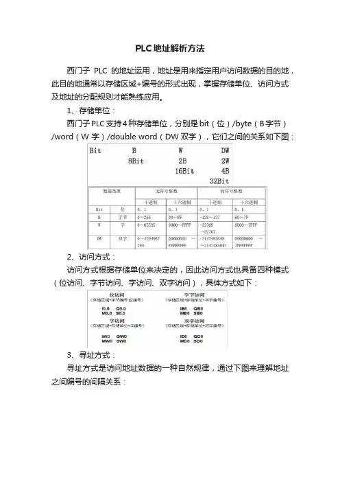
西门子PLC的地址运用,地址是用来指定用户访问数据的目的地,此目的地通常以存储区域+编号的形式出现,掌握存储单位、访问方式及地址的分配规则才能熟练应用。
1、存储单位:
西门子PLC支持4种存储单位,分别是bit(位)/byte(B字节)/word(W 字)/double word(DW双字),它们之间的关系如下图:
2、访问方式:
访问方式根据存储单位来决定的,因此访问方式也具备四种模式(位访问、字节访问、字访问、双字访问),具体方式如下:
3、寻址方式:
寻址方式是访问地址数据的一种自然规律,通过下图来理解地址之间编号的间隔关系:
在存储单位之间高位和低位所描述的也就是位权的高低问题
例如:IB0 内的8 个位的状态是10010000.那么此时可得出在IB0 里面所存储的十进制数为:128+16=144 十六进制数为:90
在使用地址时,需要注意的是字节类型地址的字节编号需要间隔一个单位,而字类型地址的字编号需要间隔两个单位,同理双字类型地址的双字编号需要间隔四个单位。
例如:字类型地址分配
例如:双字类型地址分配。
第3章+S7-200系列PLC硬件资源及编址方式
节、字或双字来存取位存储器区。格式为
位:M[字节地址].[位地址],如M26.7 字节,字,双字:M[长度][起始字节地址],如MB6, MW16,MD20 取值范围M0.0~M31.7共32个字节
18
5.顺序控制继电器(S)存储器区编址
顺序控制继电器位(S)用于组织机器操作或进入等效程 序段的步控制。顺序控制继电器(SCR)提供控制程序的逻 辑分段,可以按位、字或双字来存取S位。 格式:
储器作为间接编址的指针,但不能作为间接编址的存储器区。
格式:
位
字节,字,双字
L[字节地址].[位地址]
L[长度][起始字节地址]
L1.1
LB5,LW4,LD10
30
8.定时器(T)存储器区编址
S7-200 CPU中,定时器是累计时间增量的设备。S7-200定时 器精度(时基增量)有1ms,10ms,100ms三种。有两个相关的 变量: (1)当前值。是一个16位符号整数,存取定时器所累计的时
(BCD码形式存放); 双字DW(Double Word)—四字节数据,占存储 器中的32位。
11
•数据类型及数据范围
S7-200系列PLC的数据类型可以是字符串、布尔型(0或
1)、整数型和实数型(浮点数)。如表所示。
数据类型、长度及数据范围 无符号整数范围 十进制 0~255 0~65 535 0~4 294 967 295 十六进制 0~FF 0~FFFF 0~FFFFFFFF 符号整数范围 十进制 -128~127 -32 768~32 767 -2 147 483 648~ 2 147 483 647 十六进制 80~7F 8000~7FFF 80000000~7FFFFFFF
字节地址 字节3(第4个字节) 存储器标识符
Allen-Bradley PLC-2 控制器编址参考手册说明书

Addressing Reference ManualPLC-2® Family Programmable ControllersAllen-BradleyBecause of the variety of uses for the products described in thispublication, those responsible for the application and use of this control equipment must satisfy themselves that all necessary steps have been taken to assure that each application and use meets all performance and safety requirements, including any applicable laws, regulations, codes and standards.The illustrations, charts, sample programs and layout examples shown in this guide are intended solely for purposes of example. Since there are many variables and requirements associated with any particularinstallation, Allen-Bradley does not not assume responsibility or liability (to include intellectual property liability) for actual use based upon the examples shown in this publication.Allen-Bradley publication SGI–1.1, Safety Guidelines for the Application,Installation, and Maintenance of Solid-State Control (available from your local Allen-Bradley office), describes some important differences between solid-state equipment and electromechanical devices that should be taken into consideration when applying products such as those described in this publication.Reproduction of the contents of this copyrighted publication, in whole or in part, without written permission of Allen-Bradley company, Inc., is prohibited.Throughout this manual we make notes to alert you to possible injury to people or damage to equipment under specific circumstances.Warnings and Cautions: identify a possible trouble spot tell what causes the troublegive the result of improper actiontell the reader how to avoid troubleImportant: We recommend that you frequently back up your application programs on an appropriate storage medium to avoid possible data lossPLC and PLC-2 are registered trademarks of Allen-Bradley Company, Inc.Important User Information11Addressing PLC-2 MemoryThis addressing reference helps you specify the addresses in the memory of PLC-2® family of processors. This reference contains:For This Subject:Refer to:memory maps for various PLC-2 processorspage 2addressing page 10address formats page 11timer and counter wordspage 12For more information about memory configuration and use in PLC-2family of processors, refer to the appropriate processor manual, as listed in Table 1.A.T able 1.APLC-2 Processor ManualsUsing this Addressing ReferenceRelated Publications2Figures 1 thru 7 show how memory is organized in various PLC-2 processors. Use Table 1.B to locate the memory map for a specific processor.T able 1.BMemory Maps in this Addressing ReferenceFor each PLC-2 processor, you can alter the factory configuration of memory. Consult with the PLC® programmer to determine the exact configuration for a particular processor. Also refer to the appropriate processor manual (Table 1.A).For each PLC-2 processor, each word of memory has the PLC data type of unsigned word.Memory Maps33Figure 1Memory Map of the PLC-2/30Word Address (Octal)0000070100170200260300771001071101772002773003774005776007771000117717577377770271200Important: The PLC user can alter the size and configuration of the data table thru programming software. Consult with the PLC programmer to determine the exact configuration of memory for a particular processor.Default Data Table (128words)Data table can be expanded in 2-word increments from word 200 to word 377.Data table can be expanded in 128-wordincrements from word 400 to word 17577 (8K-word memory) or 17777 (16K-word memory).Maximum Size of Data Table (8064 or 8192 words)1 If not configured for output image table, can be used for storage or timer/counter accumulated values.2 Bits in this word are used by the processor for battery-low condition, message generation, and Data Highway.3 If not configured for input image table, can be used for storage or timer/counter preset values.4 In a remote I/O system, bits in words 125 and 126 indicate remote I/O rack fault status./ Indicates that the size of this section is adjustable.Memory size is 8192 or 16384 words4Figure 2Memory Map of PLC-2/20 (1772-LP1)Word Address (Octal)00000701001702002603004705007710010711011712014715017720027730037717777027Important: The PLC user can alter the size and configuration of the data table thru programming software. Consult with the PLC programmer to determine the exact configuration of memory for a particular processor.Default Data Table (128words)Data table can be expanded in 2-word increments from word 200 to word 377.Maximum Size of Data Table (256 words)1 If not configured for output image table, can be used for storage or timer/counter accumulated values.2 Bits in this word are used by the processor for battery-low condition, message generation, and Data Highway.3 If not configured for input image table, can be used for storage or timer/counter preset values.4 In a remote I/O system, bits in words 125 and 126 indicate remote I/O rack fault status./ Indicates that the size of this section is adjustable.Memory size is 8192 words55Figure 3Memory Map of PLC-2/20 (1772-LP2)Word Address (Octal)0000070100170200260300771001071101772002773003774005776007771000117717577177770271200Important: The PLC user can alter the size and configuration of the data table thru programming software. Consult with the PLC programmer to determine the exact configuration of memory for a particular processor.Default Data Table (128words)Data table can be expanded in 2-word increments from word 200 to word 377.Data table can be expanded in 128-word increments from word 400 to word 17577.Maximum Size of Data Table (8064 words)1 If not configured for output image table, can be used for storage or timer/counter accumulated values.2 Bits in this word are used by the processor for battery-low condition, message generation, and Data Highway.3 If not configured for input image table, can be used for storage or timer/counter preset values.4 In a remote I/O system, bits in words 125 and 126 indicate remote I/O rack fault status./ Indicates that the size of this section is adjustable.Memory size is 8192 words6Figure 4Memory Map of PLC-2/15Word Address (Octal)00000701001702002603007710010711011712012713017720027730037735773777027Important: The PLC user can alter the size and configuration of the data table thru programming software. Consult with the PLC programmer to determine the exact configuration of memory for a particular processor.Default Data Table (128words)Maximum Size of Data Table (1920 words)1 Can not be used for accumulated values.2 Not available for storage word. Bits in this word are used by the processor for battery-low condition, messagegeneration,EEPROM transfer, and Data Highway.3 Unused timer/counter words can reduce data-table size and increase user program area.4 Can not be used for preset values.5 Do not user word 127 for block-transfer storage./ Indicates that the size of this section is adjustable.Memory size is 2048 wordsMinimum Size of Data Table is 48 words40077Figure 5Memory Map of PLC-2/05Word Address (Octal)00000701001702002603007710010711011712012713017720027730037755775777027Important: The PLC user can alter the size and configuration of the data table thru programming software. Consult with the PLC programmer to determine the exact configuration of memory for a particular processor.Default Data Table (128words)Maximum Size of Data Table (2944 words)1 Can not be used for accumulated values.2 Not available for storage word. Bits in this word are used by the processor for battery-low condition, messagegeneration,EEPROM transfer, and Data Highway.3 Unused timer/counter words can reduce data-table size and increase user program area.4 Can not be used for preset values.5 Do not user word 127 for block-transfer storage./ Indicates that the size of this section is adjustable.Memory size is 3072 wordsMinimum Size of Data Table is 48 words4008Figure 6Memory Map for PLC-2Word Address (Octal)000007010017020026030077100107110117120127130177200777027Important: The PLC user can alter the size and configuration of the data table thru programming software. Consult with the PLC programmer to determine the exact configuration of memory for a particular processor.Default and Maximum Size of Data Table (128words)1 Can not be used for accumulated values.2 Not available for storage word. Bits in this word are used by the processor for battery-low condition, messagegeneration,and Data Highway.3 Unused timer/counter words can reduce data-table size and increase user program area.4 Can not be used for preset values./ Indicates that the size of this section is adjustable.Memory size of 1772-LN1 is 512 words.Memory size of 1772-LN2, -LN3 is 1028 words.Minimum Size of Data Table is 48 words99Figure 7Memory Map for PLC-2/02, -2/16, -2/17 ProcessorWord Address (Octal)User Program00000701001702002603004705007710010711014715017720037740057717777027Important: The PLC user can alter the size and configuration of the data table thru programming software. Consult with the PLC programmer to determine the exact configuration of memory for a particular processor.Default Data Table (128words)Data table can be expanded in 128-word increments from word 200 to maximum addressMaximum Mini-PLC-2/02 Data Table size is 1920 words.Maximum Mini-PLC-2/16 Data Table size is 3968 words.Maximum Mini-PLC-2/17 Data Table size is 7808 words.1 If not configured for output image table, can be used for storage.2 Not available for storage. Used by the processor for battery-low condition, message generation, EEPROM transfer ,and Data Highway.3 If not configured for output image table, can be used for storage or timer/counter preset values.4 If not configured for input image table, can be used for storage5 If not configured for input image table, can be used for storage or timer/counter preset values./ Indicates that the size of this section is adjustable.Mini-PLC-2/02 memory size is 2048 words. 3777 (Mini-PLC-2/02)Mini-PLC-2/16 memory size is 4096 words.. 7777 (Mini-PLC-2/16)Mini-PLC-2/17 memory size is 7936 words. 17377(Mini-PLC-2/17)Minimum Size of Data Table is 48 words6003577 (Mini-PLC-2/02)7577 (Mini-PLC-2/16)17177 (Mini-PLC-2/7)10All data in PLC-2 memory is stored in 16-bit words. You address this data by word number and (optionally) bit number. You must express word and bit numbers in octal form.Locating Addressing InformationThe remainder of this addressing reference provides addressing formats and data structures for addressing various PLC-2 memory sections. Use Table 1.C to locate information about a specific topic.T able 1.CAddressing Formats and Data StructuresAddressing1111Figure 8General Format for Data T able AddressesNote: Maximum allowed word number varies according to the memory configuration of the processorFigure 9Format for I/O Image T ables AddressesNote:processor Address Formats12Figures 10 thru 13 show the format in which accumulated values, preset values, and control conditions are stored in data-table words for timers and counters. Consult with the PLC programmer to determine specific word addresses for timers and counters. Refer to the appropriate Programming and Operations Manual (Table 1.A) for more information.Figure 10Structure of T imer Accumulated Value W ordFigure 11Structure of T imer Preset V alue W ord171615141312111076543210MostSignificantDigitMiddleDigitLeastSignificantDigit Unused Preset V alue in BCD FormTimer and Counter Words1313Figure 12Structure of Counter Accumulated V alue W ordFigure 13Structure of Counter Preset Value W ord17161514131211107654321Most Significant DigitMiddle DigitLeast Significant DigitUnused Preset V alue in BCD Form11Algeria • Argentina • Australia • Austria • Bahrain • Belgium • Brazil • Bulgaria • Canada • Chile • China, PRC • Colombia • Costa Rica • Croatia • Cyprus • Czech Republic Denmark • Ecuador • Egypt • El Salvador • Finland • France • Germany • Greece • Guatemala • Honduras • Hong Kong • Hungary • Iceland • India • Indonesia • Israel • Italy Jamaica • Japan • Jordan • Korea • Kuwait • Lebanon • Malaysia • Mexico • New Zealand • Norway • Oman • Pakistan • Peru • Philippines • Poland • Portugal • Puerto Rico Qatar • Romania • Russia–CIS • Saudi Arabia • Singapore • Slovakia • Slovenia • South Africa, Republic • Spain • Switzerland • T aiwan • Thailand • The Netherlands • T urkey United Arab Emirates • United Kingdom • United States • Uruguay • V enezuela • Y ugoslaviaAllen-Bradley Headquarters, 1201 South Second Street, Milwaukee, WI 53204 USA, T el: (1) 414 382-2000 Fax: (1) 414 382-4444Allen-Bradley, a Rockwell Automation Business, has been helping its customers improve productivity and quality for 90 years. W e design, manufacture, and support a broad range of control and automation products worldwide. They include logic processors, power and motion control devices, man-machine interfaces, sensors, and a variety of software. Rockwell is one Publication 5000-6.4.6 February 1995Supersedes Publication 5000-6.4.6 March 1992PN 504633103Copyright 1995 Allen-Bradley Company, Inc. Printed in USA。
西门子PLC的地址的分配方式
西门子PLC的地址的分配方式根据不同的PLC配置情况确定I/O地址是PLC编程的前提与基础,程序中的地址必须与实际物理连接点一一对应,才能确保动作的正确执行。
当选择了PLC之后,首先需要确定的是系统中各I/O 点的绝对地址。
在西门子S7系列PLC中I/O绝对地址的分配方式共有固定地址型、自动分配型、用定义型3种。
实际所使用的方式决定于所采用的PLC的CPU型号、编程软件、软件版本、编程人员的选择等因素。
1.固定地址型固定地址分配方式是一种对PLC安装机架上的每一个安装位置(插槽)都规定地址的分配方式。
其特点如下:①PLC的每一个安装位置都按照该系列PLC全部模块中可能存在的最大I/O点数分配地址。
例如:S7-300系列I/O模块中最大开关量输入/输出为32点,因此,每一个安装位置都必须分配32点地址:如果实际安装的模块只有16点输入,那么剩余的I/O地址将不可以再作为物理输入点使用。
②对于输入或输出来说,I/O地址是间断的,而且,在输入与输出中不可以使用相同的二进制字节与位。
例如:S7-300系列I/O模块的第1安装位中安装了32点输入模块,地址数据中的0.0~3.7就被该模块所占用,地址固定为I0.0~13.7;即使第2安装位中安装了32点输出模块,其输出地址也只能是Q4.O~Q7.7,而不可以是QO.O~Q3.7,在实际编程时QO.O~Q3.7就变成了不存在的输出。
同样,如果在第3安装位中接着安装了16点输入模块,其地址将为I8.0~19.7,在实际编程时I4.0~17.7就变成了不存在的输入。
以上分配原则对模拟量模块同样适用。
2.自动分配型自动地址分配方式是一种通过自动检测PLC所安装的实际模块,自动、连续分配地址的分配方式。
其特点如下:①PLC的每一个安装位置的I/O点数量无规定,PLC根据模块自动分配地址。
例如:当每一个安装位置安装了32点模块后,PLC自动分配给该模块0.0~3.7的地址:如果实际安装的模块只有16点输入,那么PLC自动分配给该模块的地址就成为0.0~1.7。
2浅谈PLC应用系统设计的原则及方法
OCCUPATION1722010 4浅谈PLC应用系统设计的原则及方法文/徐小明 马新合PLC控制系统的设计工作应该在一定的设计原则指导下,严格按步骤有序地进行。
一、PLC控制系统设计的步骤第一,深入细致地了解和分析被控对象的控制要求,确定输入、输出设备的类型和数量。
第二,根据输入、输出设备的类型和数量,确定PLC的输入/输出点数,并选择相应点数的PLC机型。
第三,在硬件设计中要合理分配输入/输出点数,控制台、控制柜的设计和选择,操作面板的设计,并绘制PLC控制系统输入、输出端子接线图。
第四,系统软件设计,就是根据控制要求绘制工作循环图或状态流程图,并编写用户程序。
第五,将用户程序输入到PLC内部存储器中,进行程序调试。
第六,调试过程结束,整理技术资料,投入使用。
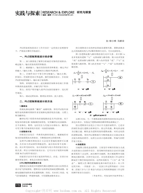
二、PLC控制系统设计的方法1.翻译法将继电器电路图“翻译”成梯形图,即用PLC的外部硬件接线和梯形图软件来实现继电器系统的功能,习惯上称为翻译法。
翻译法用于将简单的控制线路改造为PLC控制,对于较复杂的继电器-接触器控制系统,仅用翻译法反而麻烦,且不易修改、整理,这时往往与其他方法相结合,翻译法可用于整个控制系统中的某一局部控制线路。
2.经验设计法经验设计法是在一些典型电路的基础上,根据被控对象对控制系统的具体要求,不断修改和完善梯形图。
这种PLC梯形图的设计方法没有普遍的规律可以遵循,具有很大的试探性和随意性,最后的结果不是唯一的,设计所用的时间、设计的质量与设计者的经验有很大的关系,所以又叫做经验设计法,它可以用于较简单的梯形图(如手动程序)的设计。
经验设计法具有设计速度快等优点,但是,在设计问题变得复杂时,难免会出现设计漏洞。
3.PLC程序的逻辑设计法逻辑设计法就是应用逻辑代数以逻辑组合的方法和形式设计电气控制系统。
逻辑设计法的理论基础是逻辑函数,而继电接触控制的本质是逻辑线路。
因此,从本质上来说,电气控制线路是一种逻辑电路,可用逻辑函数来表示。
S7-200系列PLC地址分配原则
0.1 0.2 0.3
2L 0.4 0.5 0.6 0.7 1.0 3L 1.1 1.2 1.3 1.4 1.5 1.6 1.7
N L1 AC
1M 0.0 0.1 0.2 0.3 0.4 0.5 0.6 0.7 1.0 1.1 1.2 1.3 1.4 2M 1.5 1.6 1.7 2.0 2.1 2.2
2.
0.4 0.5 0.6 0.7 1.0
第二组由输入端子I1.5~I1.7、I2.0~I2.7共11个输入点组成,各输入端子
的3L接1线.1 与1.第2 一1.3组1类.4似1.,5 公1.6共1端.7为2M。 N L1 AC
地址分配示例
CPU224 4入/4出EM223 8入EM221 4入/1出EM235
CPU
扩展1
扩展2
扩展3
I0.0~I1.5 Q0.0~Q1.1
I2.0~I2.3 Q2.0~Q2.3
I3.0~I3.7
AIW0~AIW6 AQW0
CPU226AC/DC/继电器模块输入、输出单元的接
线图
16点输出
S7-200系列PLC地址分配原则
● 第一是数字量和模拟量分别编址,数字量输入地址冠以字母“I”,数字量 输出地址冠以字母“Q”,输出/输入字节可以重号。模拟量输入地址冠以字母 “AI”,模拟量输出地址冠以字母“AQ”,输出/输入字可以重号。
● 第二是数字量模块的编址是以字节为单位,如:IB0、Q0.1,模拟量模块的 编址是以字为单位(即以双字节为单位)如:AIW0,AQW2。
2L 0.4 0.5 0.6 0.7 1.0
2.第二组由输出端子Q0.4~Q0.7、Q1.0共5个输出点与公共端2L组成
1L 0.0 0.1 0.2 0.3
02 第2章 PLC硬件资源与编址方式
3)字类型:
CPU按照“字” 方式访问一组相邻输出继电器的值。 每个字16位。 例:QW0由QB0和QB1组成,即由Q0.0-Q0.7和Q1.0Q1.7这16位组成。同样,在QW0中,QB0占高8位, QB1占低8位。
4)双字类型:
CPU按照“双字” 方式访问一组相邻输出继电器的 值。每个双字32位。 例:QD4表示输出映像寄存器中编号为4的双字,它 由QB4、QB5、QB6、QB7这4个字节组成。 注意:在QD4中,QB4占高8位, QB5次之… QB7占低8位。 17
ID0
注意: 在ID0中,IB0占高8位, IB1次之…IB3 占低8位。 双字类型数据常按4的倍数递增的方式编址。
14
2. 输出继电器(Q) ● 与PLC的输出端子对应,决定输出端子
所接外部负载的工作状态。 ● 程序中的输出线圈得电,相应的外部负 载通电 ● 输出继电器有常开常闭触点,可用于程 序中
12
3)字类型: CPU按照“字” 方式读取一组相邻输入继电器的 值 例:IW0表示输入映像寄存器中编号为0的字,它 由IB0和IB1组成,即由I0.0-I0.7和I1.0-I1.7这16 MSB 位组成。 LSB
I0.7 I0.6 I0.5 I0.4 I0.3 I0.2 I0.1 I0.0 I1.7 I1.6 I1.5 I1.4 I1.3 I1.2 I1.1 I1.0 IB0 IB1
存储区域标识符
9
2. 字节地址(8 Bit)
IB0
字节地址 字节标识符 存储区域标识符
3. 字地址(16 Bit)
4. 双字地址(32 Bit)
ID0
字节地址
双字标识符 存储区域标识符
IW0
字节地址 字标识符 存储区域标识符
PLC程序设计步骤及编程技巧
01001 01000
01000 01001
7.2.3 时间控制
00000 01000 00001
(a)启动优先型
01000
00000 HR00
HR00 00001
HR00 01000
(c)启动优先断电保持型
00000 00001 01000
01000
(b)停止优先型
00000 00001 HR01
图7-14 电动机正、反转主电路及控制电路
2.I/O分配
从图7-14可见,为满足控制要求,需要有3个按钮:正 转启动按钮、反转启动按钮和停止按钮。此外还需要控制电 动机正、反转的两个交流接触器,一个热继电器作为过载保 护。共需5个I/O点,其中3个输入,2个输出。
输入信号:正转启动按钮 SB1—00000; 反转启动按钮 SB2—00001; 停止按钮 SB3—00002。
图7-19 梯形图设计
7.3.3 送料小车控制
1.控制要求 如图7-20所示,有一辆送料车自动循环运料。
图7-20 送料车自动循环运料
小车处于起始位置时,CK0闭合;系统启动后, 小车在起始位置装料,20s后向右,到CK1位置时, CK1闭合,小车下料15s;小车下料后返回到起始位置, 再用20s的时间装料,其后向右运动到CK2位置,此时 CK2闭合,小车下料15s后返回到起始位置。以后重复 上述过程,直至有停车复位信号为止。
(3)对热继电器的处理
若PLC的输入点较富裕,热继电器的常闭触点可占 用PLC的输入点;若输入点较紧张,热继电器的信号可 不输入PLC中,而直接接在PLC外部的控制电路中。
7.3.2 三相异步电动机 的点动、长动控制
1.控制要求 电动机可以实现长动,也可以实现点动,具有短路、 失压、欠压和过载保护功能。 三相异步电动机的点动、长动继电器接触器控制电 路如图7-17所示。
PLC系统方案设计
PLC系统方案设计PLC系统方案设计随着工业自动化技术的发展,越来越多的企业开始采用PLC控制系统进行生产自动化。
PLC系统方案设计是PLC控制系统建设中至关重要的一步,它是实现可靠、安全、高效工业自动化的重要保障。
本文将详细介绍PLC系统方案设计的相关内容,包括PLC系统基础知识、PLC系统方案设计模板、PLC系统方案设计流程等。
1. PLC系统基础知识PLC系统是指通过电子设备来控制机器、生产线和机房等设备。
PLC系统的核心是PLC,它是一种计算机控制器,通常用于工业生产中的机器和设备自动化控制。
PLC系统最常见的应用包括动力系统控制、自动化生产线及机房管理。
在PLC系统设计前,需要明确自己的自动化需求和预期效果。
2. PLC系统方案设计模板在PLC系统方案设计中,需要根据自己的实际需要来选择相应的模板。
通常,PLC系统方案设计模板会涉及到PLC系统结构设计、PLC程序设计、控制系统硬件配置等方面。
PLC系统方案设计模板可以帮助使用者更好地掌握PLC系统设计的流程和技术要点。
3. PLC系统方案设计流程PLC系统方案设计流程包括PLC选型、可行性研究、方案设计报告撰写、系统实施和系统维护等流程。
下面,将详细介绍PLC系统方案设计流程的每一个步骤。
3.1 PLC选型PLC系统方案设计首先要确定具体选择什么样的PLC。
需要根据自己的自动化需求和预期效果来选择。
一般情况下,PLC 的选择应考虑以下几个因素:PLC控制范围、控制模式、安全控制、通信性能、编程语言等。
3.2 可行性研究可行性研究是PLC系统方案设计中非常关键的一步。
可行性研究旨在确立一个可行的PLC系统方案,为PLC系统方案设计的推广和实施提供依据。
在可行性研究的过程中,通常会进行成本分析、质量分析、市场调研、技术评估等工作,以确定PLC系统方案的可行性和可行性研究报告。
3.3 方案设计报告撰写方案设计报告是PLC系统方案设计中的重要文献,在PLC 系统方案设计的过程中也是一个非常重要的参考。