Cisco路由器静态路由配置实例
静态路由实验报告
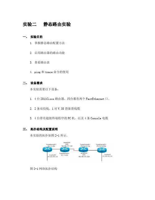
实验二静态路由实验一、实验目的1. 掌握静态路由配置方法2. 启用路由器的路由功能3. 查看路由表4. ping和trace命令的使用二、设备需求本实验需要以下设备:1. 4台2811Cisco路由器,四台都有两个FastEthernet口。
2. 2条双绞线,1对V.35背靠背线缆3. 4台带有超级终端程序的PC机,以及4条Console电缆三、拓扑结构及配置说明本实验的拓扑如图2-1所示。
图2-1网络拓扑结构4台路由器分别命名为R1、R2、R3和R4。
所使用的ip地址分配如图1-1所示。
图中的“/24”表示子网掩码为24位,即255.255.255.0。
实验中,应使用静态路由的设置,实现R1到R4在IP层的连通性,即要求从R1可以ping通R4,反之亦然。
四、实验步骤1. 恢复路由器的初始配置。
(若路由器末被配置过则直接做第三步)2. 给路由器命名router>enable //进入特权模式Router #config terminal //进入配置模式Enter configuration commands, one per line. End with CNTL/Z.Router (config) #Router (config)#hostname r1 //给路由器命名R1 (config)#其它路由器配置类似3. 配置端口IPR1 (config)# interface FastEthernet0/1 //进入FastEthernet0/1端口r1(config-if)#ip address 10.1.1.1 255.255.255.0 //指定端口的IP地址及子网掩码r1(config-if)#no shut //开启端口r1(config-if)#exit //退出端口模式R1 (config)#interface Loopback0 //进入本地回环接口0r1(config-if)#ip address 192.168.100.1 255.255.255.0其它路由器配置类似配完各个路由器的名字及IP后,通过sh run(特权模式下的命令)命令查看路由器的配置把你所看到的结果记录下来。
Cisco(思科)路由器静态路由的配置
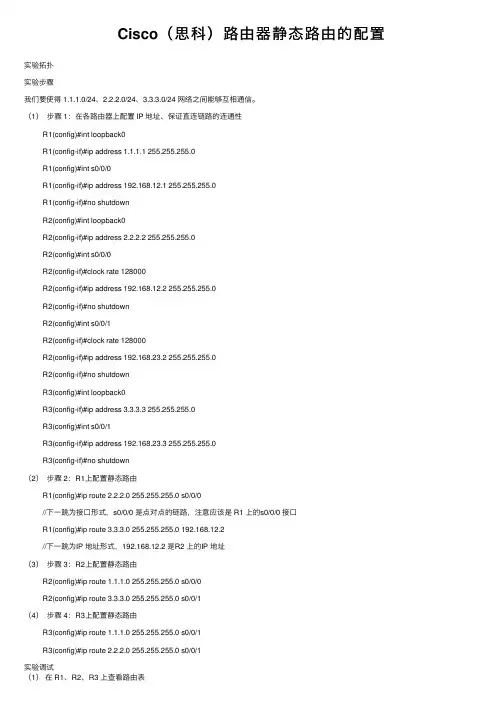
Cisco(思科)路由器静态路由的配置实验拓扑实验步骤我们要使得 1.1.1.0/24、2.2.2.0/24、3.3.3.0/24 ⽹络之间能够互相通信。
(1)步骤 1:在各路由器上配置 IP 地址、保证直连链路的连通性R1(config)#int loopback0R1(config-if)#ip address 1.1.1.1 255.255.255.0R1(config)#int s0/0/0R1(config-if)#ip address 192.168.12.1 255.255.255.0R1(config-if)#no shutdownR2(config)#int loopback0R2(config-if)#ip address 2.2.2.2 255.255.255.0R2(config)#int s0/0/0R2(config-if)#clock rate 128000R2(config-if)#ip address 192.168.12.2 255.255.255.0R2(config-if)#no shutdownR2(config)#int s0/0/1R2(config-if)#clock rate 128000R2(config-if)#ip address 192.168.23.2 255.255.255.0R2(config-if)#no shutdownR3(config)#int loopback0R3(config-if)#ip address 3.3.3.3 255.255.255.0R3(config)#int s0/0/1R3(config-if)#ip address 192.168.23.3 255.255.255.0R3(config-if)#no shutdown(2)步骤 2:R1上配置静态路由R1(config)#ip route 2.2.2.0 255.255.255.0 s0/0/0//下⼀跳为接⼝形式,s0/0/0 是点对点的链路,注意应该是 R1 上的s0/0/0 接⼝R1(config)#ip route 3.3.3.0 255.255.255.0 192.168.12.2//下⼀跳为IP 地址形式,192.168.12.2 是R2 上的IP 地址(3)步骤 3:R2上配置静态路由R2(config)#ip route 1.1.1.0 255.255.255.0 s0/0/0R2(config)#ip route 3.3.3.0 255.255.255.0 s0/0/1(4)步骤 4:R3上配置静态路由R3(config)#ip route 1.1.1.0 255.255.255.0 s0/0/1R3(config)#ip route 2.2.2.0 255.255.255.0 s0/0/1实验调试(1)在 R1、R2、R3 上查看路由表R1#show ip routeCodes: C - connected, S - static, R - RIP, M - mobile, B - BGPD - EIGRP, EX - EIGRP external, O - OSPF, IA - OSPF inter areaN1 - OSPF NSSA external type 1, N2 - OSPF NSSA external type 2E1 - OSPF external type 1, E2 - OSPF external type 2 i - IS-IS, su - IS-IS summary, L1 - IS-IS level-1, L2 - IS-IS level-2 ia - IS-IS inter area, * - candidate default, U - per-user static routeo - ODR, P - periodic downloaded static routeGateway of last resort is not setC 192.168.12.0/24 is directly connected, Serial0/0/01.0.0.0/24 is subnetted, 1 subnetsC 1.1.1.0 is directly connected, Loopback02.0.0.0/24 is subnetted, 1 subnetsS 2.2.2.0 is directly connected, Serial0/0/03.0.0.0/24 is subnetted, 1 subnetsS 3.3.3.0 [1/0] via 192.168.12.2R2#show ip routeCodes: C - connected, S - static, R - RIP, M - mobile, B - BGPD - EIGRP, EX - EIGRP external, O - OSPF, IA - OSPF inter areaN1 - OSPF NSSA external type 1, N2 - OSPF NSSA external type 2E1 - OSPF external type 1, E2 - OSPF external type 2i - IS-IS, su - IS-IS summary, L1 - IS-IS level-1, L2 - IS-IS level-2ia - IS-IS inter area, * - candidate default, U - per-user static routeo - ODR, P - periodic downloaded static routeGateway of last resort is not setC 192.168.12.0/24 is directly connected, Serial0/0/01.0.0.0/24 is subnetted, 1 subnetsS 1.1.1.0 is directly connected, Serial0/0/02.0.0.0/24 is subnetted, 1 subnetsC 2.2.2.0 is directly connected, Loopback03.0.0.0/24 is subnetted, 1 subnetsS 3.3.3.0 is directly connected, Serial0/0/1C 192.168.23.0/24 is directly connected, Serial0/0/1R3#show ip routeCodes: C - connected, S - static, R - RIP, M - mobile, B - BGPD - EIGRP, EX - EIGRP external, O - OSPF, IA - OSPF inter areaN1 - OSPF NSSA external type 1, N2 - OSPF NSSA external type 2E1 - OSPF external type 1, E2 - OSPF external type 2i - IS-IS, su - IS-IS summary, L1 - IS-IS level-1, L2 - IS-IS level-2ia - IS-IS inter area, * - candidate default, U - per-user static routeo - ODR, P - periodic downloaded static routeGateway of last resort is not set1.0.0.0/24 is subnetted, 1 subnetsS 1.1.1.0 is directly connected, Serial0/0/12.0.0.0/24 is subnetted, 1 subnetsS 2.2.2.0 is directly connected, Serial0/0/13.0.0.0/24 is subnetted, 1 subnets C 3.3.3.0 is directly connected, Loopback0C 192.168.23.0/24 is directly connected, Serial0/0/1(2)从各路由器的环回⼝ ping 其他路由器的环回⼝:R1#ping//不带任何参数的 ping命令,允许我们输⼊更多的参数Protocol [ip]:Target IP address: 2.2.2.2 //⽬标IP地址Repeat count [5]: //发送的ping 次数Datagram size [100]: //ping包的⼤⼩Timeout in seconds [2]: //超时时间Extended commands [n]: y //是否进⼀步扩展命令Source address or interface: 1.1.1.1 //源IP地址Type of service [0]:Set DF bit in IP header? [no]:Validate reply data? [no]:Data pattern [0xABCD]:Loose, Strict, Record, Timestamp, Verbose[none]:Sweep range of sizes [n]:Type escape sequence to abort.Sending 5, 100-byte ICMP Echos to 2.2.2.2, timeout is 2 seconds:Packet sent with a source address of 1.1.1.1Success rate is 100 percent (5/5), round-trip min/avg/max = 12/14/16 ms//以上说明从 R1 的 loopback0 可以ping 通R2 上的 loopback0。
静态路由(cisco)
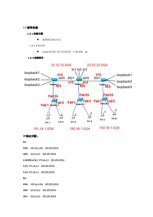
1.5教学实验 1.5.1实验主题●配置静态路由协议1.5.2实验设备●cisco 路由器 超五类双绞线 V.35线缆 pc1.5.3实验拓扑IP 地址分配:R1:F0/0: 191.16.1.254 255.255.255.0 S0/0: 12.12.12.1 255.255.255.0 LOOPBACK1: 171.16.1.1 255.255.255.0 LO2: 171.16.2.1 255.255.255.0 LO3: 171.16.3.1 255.255.255.0 R2:F0/0: 192.16.1.254 255.255.255.0 S0/0: 23.23.23.2 255.255.255.0 S0/1: 12.12.12.2 255.255.255.0s0/0 s0/0 S0/1S0/1 loopback1 lo1 lo2 lo3loopback2 loopback3loopback1 loopback2loopback3DCEDCEDTEDTE12.12.12.0/24 23.23.23.0/24191.16.1.0/24192.16.1.0/24193.16.1.0/24f0/0 f0/0 f0/0 Fa0/24Fa0/24Fa0/24 Fa0/1Fa0/1Fa0/1Fa0/2 Fa0/2 Fa0/2.1.2.1.1.2.2LO1: 172.16.1.1 255.255.255.0LO2: 172.16.2.1 255.255.255.0LO3: 172.16.3.1 255.255.255.0R3:F0/0: 193.16.1.254 255.255.255.0S0/1: 23.23.23.3 255.255.255.0LO1: 173.16.1.1 255.255.255.0LO2: 173.16.2.1 255.255.255.0LO3: 173.16.3.1 255.255.255.0PC1:191.16.1.1 255.255.255.0PC2:191.16.1.2 255.255.255.0PC3:192.16.1.1 255.255.255.0PC4:192.16.1.2 255.255.255.0PC5:193.16.1.1 255.255.255.0PC6:193.16.1.2 255.255.255.0Sw1: 191.16.1.253 255.255.255.0Sw2: 192.16.1.253 255.255.255.0Sw3: 193.16.1.253 255.255.255.01.5.4实验要求●通过静态路由的配置使不同网段能够相互通信。
Cisco路由器静态、动态路由配置
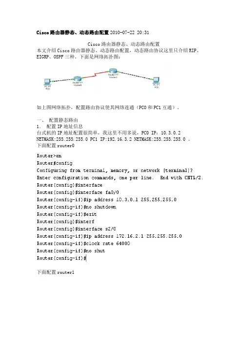
Cisco路由器静态、动态路由配置2010-07-22 20:31Cisco路由器静态、动态路由配置本文介绍Cisco路由器静态、动态路由配置,动态路由协议这里只介绍RIP、EIGRP、OSPF三种。
下面是网络拓扑图:如上图网络拓扑,配置路由协议使其网络连通(PC0和PC1互通)。
一、配置静态路由1.配置IP地址信息台式机的IP地址配置很简单,我这里不用多说,PC0 IP:10.3.0.2 NETMASK:255.255.255.0 PC1 IP:192.16.3.2 NETMASK:255.255.255.0 。
下面配置router0下面配置router1这里我们来试试PC0和PC1互通性PC0 ping PC1如图所示:这里我们看到PC0和PC1并不能相通。
PC1 ping PC0如图所示:这里我们看到PC1和PC0也并不能相通。
2.配置静态路由协议Router(config)#ip route 192.16.3.0 255.255.255.0 172.16.2.2 R1(config)#ip route 10.3.0.0 255.255.255.0 172.16.2.1 下面我们再来试试PC0和PC1互通性PC0 ping PC1如图所示:这里我们看到PC0和PC1能相通,我们配置的静态路由协议起作用了。
PC1 ping PC0如图所示:这里我们看到PC1和PC0能相通,我们配置的静态路由协议也起作用了。
二、 RIP路由协议的配置1. 配置IP地址信息配置IP地址信息见上面配置静态路由中配置IP地址信息,我这里不多说。
这里配置了ip地址以后如静态路由中一样,PC0和PC1不能相通。
2. 配置rip路由协议配置router0Router(config)#router ripRouter(config-router)#version 2Router(config-router)#network 10.3.0.0Router(config-router)#network 172.16.2.0配置router1R1(config)#router ripR1(config-router)#version 2R1(config-router)#network 192.16.3.0R1(config-router)#network 172.16.2.03. 查看rip路由信息查看router0查看router1这里我们可以看到R开头的路由信息即是通过rip协议得到的路由信息。
思科Cisco路由器配置——浮动静态路由配置实验详解
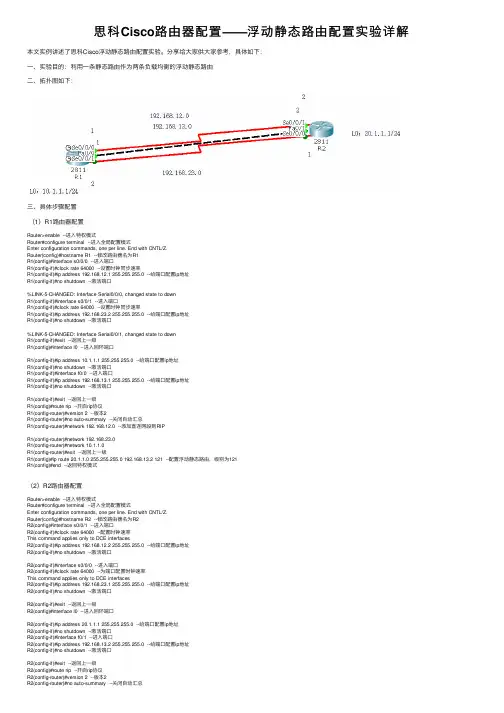
思科Cisco路由器配置——浮动静态路由配置实验详解本⽂实例讲述了思科Cisco浮动静态路由配置实验。
分享给⼤家供⼤家参考,具体如下:⼀、实验⽬的:利⽤⼀条静态路由作为两条负载均衡的浮动静态路由⼆、拓扑图如下:三、具体步骤配置(1)R1路由器配置Router>enable --进⼊特权模式Router#configure terminal --进⼊全局配置模式Enter configuration commands, one per line. End with CNTL/Z.Router(config)#hostname R1 --修改路由器名为R1R1(config)#interface s0/0/0 --进⼊端⼝R1(config-if)#clock rate 64000 --设置时钟同步速率R1(config-if)#ip address 192.168.12.1 255.255.255.0 --给端⼝配置ip地址R1(config-if)#no shutdown --激活端⼝%LINK-5-CHANGED: Interface Serial0/0/0, changed state to downR1(config-if)#interface s0/0/1 --进⼊端⼝R1(config-if)#clock rate 64000 --设置时钟同步速率R1(config-if)#ip address 192.168.23.2 255.255.255.0 --给端⼝配置ip地址R1(config-if)#no shutdown --激活端⼝%LINK-5-CHANGED: Interface Serial0/0/1, changed state to downR1(config-if)#exit --返回上⼀级R1(config)#interface l0 --进⼊回环端⼝R1(config-if)#ip address 10.1.1.1 255.255.255.0 --给端⼝配置ip地址R1(config-if)#no shutdown --激活端⼝R1(config-if)#interface f0/0 --进⼊端⼝R1(config-if)#ip address 192.168.13.1 255.255.255.0 --给端⼝配置ip地址R1(config-if)#no shutdown --激活端⼝R1(config-if)#exit --返回上⼀级R1(config)#route rip --开启rip协议R1(config-router)#version 2 --版本2R1(config-router)#no auto-summary --关闭⾃动汇总R1(config-router)#network 192.168.12.0 --添加直连⽹段到RIPR1(config-router)#network 192.168.23.0R1(config-router)#network 10.1.1.0R1(config-router)#exit --返回上⼀级R1(config)#ip route 20.1.1.0 255.255.255.0 192.168.13.2 121 --配置浮动静态路由,级别为121R1(config)#end --返回特权模式(2)R2路由器配置Router>enable --进⼊特权模式Router#configure terminal --进⼊全局配置模式Enter configuration commands, one per line. End with CNTL/Z.Router(config)#hostname R2 --修改路由器名为R2R2(config)#interface s0/0/1 --进⼊端⼝R2(config-if)#clock rate 64000 --配置时钟速率This command applies only to DCE interfacesR2(config-if)#ip address 192.168.12.2 255.255.255.0 --给端⼝配置ip地址R2(config-if)#no shutdown --激活端⼝R2(config-if)#interface s0/0/0 --进⼊端⼝R2(config-if)#clock rate 64000 --为端⼝配置时钟速率This command applies only to DCE interfacesR2(config-if)#ip address 192.168.23.1 255.255.255.0 --给端⼝配置ip地址R2(config-if)#no shutdown --激活端⼝R2(config-if)#exit --返回上⼀级R2(config)#interface l0 --进⼊回环端⼝R2(config-if)#ip address 20.1.1.1 255.255.255.0 --给端⼝配置ip地址R2(config-if)#no shutdown --激活端⼝R2(config-if)#interface f0/1 --进⼊端⼝R2(config-if)#ip address 192.168.13.2 255.255.255.0 --给端⼝配置ip地址R2(config-if)#no shutdown --激活端⼝R2(config-if)#exit --返回上⼀级R2(config)#route rip --开启rip协议R2(config-router)#version 2 --版本2R2(config-router)#no auto-summary --关闭⾃动汇总R2(config-router)#network 192.168.12.0 --添加直连⽹段到RIPR2(config-router)#network 192.168.23.0R2(config-router)#network 20.1.1.0R2(config-router)#exit --返回上⼀级R2(config)#ip route 10.1.1.0 255.255.255.0 192.168.13.1 121 --配置浮动静态路由,级别为121 R2(config)#end --返回特权模式四、验证1、分别查看R1与R2路由表信息(1)R1路由表信息(2)R2路由表信息2、断开两条负载均衡路径(12.0与23.0⽹段)并查看路由表信息(1)R1路由表信息(2)R2路由表信息解释:当两条负载均衡路径断掉,这条浮动的静态路由就会出现。
思科,静态路由实验详细配置教程
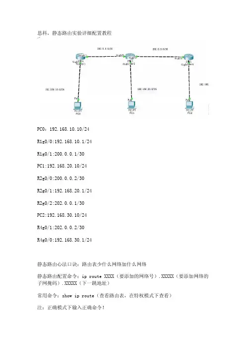
思科,静态路由实验详细配置教程PC0:192.168.10.10/24R1g0/0:192.168.10.1/24R1g0/1:200.0.0.1/30PC1:192.168.20.10/24R2g0/0:200.0.0.2/30R2g0/1:192.168.20.1/24R2g0/2:202.0.0.1/30PC2:192.168.30.10/24R4g0/1:202.0.0.2/30R4g0/0:192.168.30.1/24静态路由心法口诀:路由表少什么网络加什么网络静态路由配置命令:ip route XXXX(要添加的网络号).XXXXX(要添加网络的子网掩码).XXXXX(下一跳地址)常用命令:show ip route(查看路由表,在特权模式下查看)注:正确模式下输入正确命令!配置:R1命令:R1>en //进入特权模式R1#conf t //进入全局配置模式R1(config)#inter g0/0 //进入g0/0接口R1(config-if)#ip add 192.168.10.1 255.255.255.0 //给g0/0接口配置IP地址R1(config-if)#no shutdown //激活g0/0接口R1(config-if)#inter g0/1R1(config-if)#ip add 200.0.0.1 255.255.255.252R1(config-if)#no shutdownR1(config-if)#exit(根据心法口诀可以先在特权模式下先执行show ip route(查看路由表)看看少哪些网段少什么网段加什么网段)R1(config)#ip route 192.168.20.0(要添加网络的网络号) 255.255.255.0 200.0.0.2 (下一跳地址这里是R2路由的g0/0接口) //(配置静态路由,把192.168.20.0网络添加的R1的路由表,可以在特权模式下执行show ip route查看)R1(config)#ip route 202.0.0.0 255.255.255.252 200.0.0.2 //(将202.0.0.0段添加到路由表)R1(config)#ip route 192.168.30.0 255.255.255.0 200.0.0.2 //(将192.168.30.0段添加到路由表)R2命令:R2>enR2#conf tR2(config)#inter g0/0R2(config-if)#ip add 200.0.0.2 255.255.255.252R2(config-if)#no shutdownR2(config-if)#inter g0/1R2(config-if)#ip add 192.168.20.1 255.255.255.0R2(config-if)#no shutdownR2(config-if)#inter g0/2R2(config-if)#ip add 202.0.0.1 255.255.255.252R2(config-if)#no shutdownR2(config-if)#exitR2(config)#ip route 192.168.10.0 255.255.255.0 200.0.0.1 R2(config)#ip route 192.168.30.0 255.255.255.0 202.0.0.2R4命令:R4>enR4#conf tR4(config)#inter g0/1R4(config-if)#ip add 202.0.0.2 255.255.255.252R4(config-if)#no shutdownR4(config-if)#inter g0/0R4(config-if)#ip add 192.168.30.1 255.255.255.0R4(config-if)#no shutdownR4(config-if)#exitR4(config)#ip route 192.168.10.0 255.255.255.0 202.0.0.1 R4(config)#ip route 200.0.0.0 255.255.255.252 202.0.0.1 R4(config)#ip route 192.168.20.0 255.255.255.0 202.0.0.1用pc ping测试,全网互通有兴趣朋友可以了解更多java教程/java/video.shtml。
实验22 静态路由和默认路由配置
实验22 静态和缺省路由配置【背景知识】教材5.1-5.3, 掌握路由表的概念,理解路由表的内容,理解IP路由过程,掌握静态路由和缺省路由的配置。
静态路由为管理员在路由器中手动配置的固定路由,不能对网络的改变作出反应,用于网络规模不大、拓扑结构相对固定的网络。
【实验拓扑】使用Cisco Packet Tracer5.2 构建拓扑结构图8.30。
【实验内容】(1) 选择三台C2811 路由器,分别关闭电源后添加WIC-2T 模块,添加位置为插槽0/接口适配器0(即4个小插槽中位于右下角的那个插槽)。
添加两台计算机分别连接C2811A 和C2811B 路由器的f0/1 接口,计算机IP地址与网关设置如图所示。
注意连线的时候,要用手动连线,不要用自动连线,这样才能根据图1选择正确的接口类型和编号。
(2) 按实验线路连接图完成各个路由器接口的IP地址设置,其中serial 接口采用默认HDLC封装即可(即不用配置封装),注意DCE接口要配置时钟频率。
测试C2811A 与192.168.10.2之间、C2811A与C2811B之间、C2811A与Internet接入路由器之间相互ping 通,测试C2811B 与192.168.30.2 之间相互ping通。
(3) 完成以上配置之后,192.168.30.2 与192.168.10.2 之间无法ping通,思考无法ping通的原因是什么。
(4) 参阅教材5.3中内容,在C2811A上配置到达192.168.30.0/24的静态路由,在C2811A上配置到达Internet的缺省路由。
在C2811B上配置到达192.168.10.0/24 和Internet的缺省路由。
在Internet接入路由器上配置到达192.168.0.0/16 的静态路由。
(5) 在各台路由器上使用show ip route 查看路由表,详细理解路由表的内容。
(6) 192.168.30.2 与192.168.10.2 之间相互ping 通,192.168.30.2 与10.1.1.1 之间相互ping 通。
思科路由器配置命令详解及实例
思科路由器配置命令详解及实例思科路由器配置命令详解及实例一、路由器基本配置1.1 登录路由器为了配置和管理思科路由器,您需要登录到路由器的控制台或通过远程登录方式。
使用以下命令登录路由器,并进行必要的身份验证:```Router> enableRouterconfigure terminalEnter configuration commands, one per line: End with TL/Z:Router(config)hostname [路由器名称]Router(config)enable secret [密码]Router(config)line console 0Router(config-line)password [密码]Router(config-line)logging synchronousRouter(config-line)exitRouter(config)line vty 0 4Router(config-line)password [密码]Router(config-line)logging synchronous```1.2 配置接口接下来,您需要配置路由器的接口,以便与其他网络设备进行通信。
使用以下命令配置接口:```Router(config)interface [接口类型] [接口编号]Router(config-if)ip address [IP地址] [子网掩码]Router(config-if)no shutdownRouter(config-if)exit```二、路由配置2.1 静态路由静态路由是手动配置的路由项,将特定的网络目的地与下一跳路由器关联起来。
以下是配置静态路由的示例命令:```Router(config)ip route [目的网络] [子网掩码] [下一跳地址]```2.2 动态路由动态路由是通过路由协议动态学习并自动更新的路由项。
Cisco路由器静态路由和默认路由的配置
实验四 Cisco路由器静态路由和默认路由的配置(验证性)(2学时)一、实验目的1.进一步熟悉Cisco路由器的配置环境2.掌握Cisco路由器静态路由的配置方法3.掌握Cisco路由器默认路由的配置方法二、实验内容(一)静态路由的配置建立如上所示的拓扑结构,现在需要完成的就是让HostA能和HostB互相ping通。
具体配置如下:router1的配置:Press Enter to StartRouter>Router>enRouter#conf tEnter configuration commands, one per line. End with CNTL/Z.Router(config)#hostname router1router1(config)#interface e0router1(config-if)#ip address 192.168.1.2 255.255.255.0router1(config-if)#no shut%LINK-3-UPDOWN: Interface Ethernet0, changed state to uprouter1(config-if)#interface s0router1(config-if)#ip address 192.168.2.1 255.255.255.0router1(config-if)#clock rate 6400 //clock rate是dce设备给dte设备提供时钟频率的,需要在dce里面设置,而另外的一个路由器里面则不用设置router1(config-if)#no shut%LINK-3-UPDOWN: Interface Serial0, changed state to uprouter1(config-if)#end%LINK-3-UPDOWN: Interface Serial0, changed state to down%LINEPROTO-5-UPDOWN: Line protocol on Interface Serial0, changed state to downrouter1#config tEnter configuration commands, one per line. End with CNTL/Z.router1(config)#ip route 192.168.3.0 255.255.255.0 192.168.2.1 //设定静态路由router1(config)#ip route 192.168.2.0 255.255.255.0 192.168.2.1router1(config)#endrouter1#copy running startupDestination filename [startup-config]?Building configuration...[OK]%LINK-3-UPDOWN: Interface Serial0, changed state to up%LINEPROTO-5-UPDOWN: Line protocol on Interface Serial0, changed state to uprouter2的配置:Press Enter to StartRouter>enRouter#conf tEnter configuration commands, one per line. End with CNTL/Z.Router(config)#interface e0Router(config-if)#endRouter#config tEnter configuration commands, one per line. End with CNTL/Z.Router(config)#hostname router2router2(config)#interface s0router2(config-if)#ip address 192.168.2.2 255.255.255.0router2(config-if)#no shut%LINK-3-UPDOWN: Interface Serial0, changed state to uprouter2(config-if)#interface s0router2(config-if)#interface e0router2(config-if)#ip address 192.168.3.1 255.255.255.0router2(config-if)#no shut%LINK-3-UPDOWN: Interface Ethernet0, changed state to uprouter2(config-if)#endrouter2#config tEnter configuration commands, one per line. End with CNTL/Z.router2(config)#ip route 192.168.1.0 255.255.255.0 192.168.2.2router2(config)#ip route 192.168.2.0 255.255.255.0 192.168.2.2router2(config)#endrouter2#copy running startupDestination filename [startup-config]?Building configuration...[OK]router2#ping 192.168.1.2Type escape sequence to abort.Sending 5, 100-byte ICMP Echos to 192.168.1.2, timeout is 2 seconds:!!!!!Success rate is 100 percent (5/5), round-trip min/avg/max = 1/2/4 msrouter2#ping 192.168.2.1Type escape sequence to abort.Sending 5, 100-byte ICMP Echos to 192.168.2.1, timeout is 2 seconds:!!!!!Success rate is 100 percent (5/5), round-trip min/avg/max = 1/2/4 msrouter2#ping 192.168.2.2Type escape sequence to abort.Sending 5, 100-byte ICMP Echos to 192.168.2.2, timeout is 2 seconds:!!!!!Success rate is 100 percent (5/5), round-trip min/avg/max = 1/2/4 ms //路由器之间试ping 一下,应该可以ping通,接下来配pcpc1的配置如下:Boson BOSS 5.0Copyright 1998-2003 Boson Software, Inc.Use the command help to get startedPress Enter to beginC:>ipconfig /ip 192.168.1.1 255.255.255.0 //此时尚未指定网关C:>ping 192.168.2.1Pinging 192.168.2.1 with 32 bytes of data:Request timed out.Request timed out.Request timed out.Request timed out.Request timed out.Ping statistics for 192.168.2.1:Packets: Sent = 5, Received = 0, Lost = 5 (100% loss), //未指定网关时不能ping通router1的s0Approximate round trip times in milli-seconds:Minimum = 0ms, Maximum = 0ms, Average = 0msC:>ipconfig /dg 192.168.1.2 //指定网关为与本机直连的router1的e0口C:>ping 192.168.1.2Pinging 192.168.1.2 with 32 bytes of data:Reply from 192.168.1.2: bytes=32 time=60ms TTL=241Reply from 192.168.1.2: bytes=32 time=60ms TTL=241Reply from 192.168.1.2: bytes=32 time=60ms TTL=241Reply from 192.168.1.2: bytes=32 time=60ms TTL=241Reply from 192.168.1.2: bytes=32 time=60ms TTL=241Ping statistics for 192.168.1.2: Packets: Sent = 5, Received = 5, Lost = 0 (0% loss), Approximate round trip times in milli-seconds:Minimum = 50ms, Maximum = 60ms, Average = 55msC:>ping 192.168.2.1Pinging 192.168.2.1 with 32 bytes of data:Reply from 192.168.2.1: bytes=32 time=60ms TTL=241Reply from 192.168.2.1: bytes=32 time=60ms TTL=241Reply from 192.168.2.1: bytes=32 time=60ms TTL=241Reply from 192.168.2.1: bytes=32 time=60ms TTL=241Reply from 192.168.2.1: bytes=32 time=60ms TTL=241Ping statistics for 192.168.2.1: Packets: Sent = 5, Received = 5, Lost = 0 (0% loss), //指定网关后可以ping通s0口了Approximate round trip times in milli-seconds:Minimum = 50ms, Maximum = 60ms, Average = 55msC:>ping 192.168.2.2Pinging 192.168.2.2 with 32 bytes of data:Reply from 192.168.2.2: bytes=32 time=60ms TTL=241Reply from 192.168.2.2: bytes=32 time=60ms TTL=241Reply from 192.168.2.2: bytes=32 time=60ms TTL=241Reply from 192.168.2.2: bytes=32 time=60ms TTL=241Reply from 192.168.2.2: bytes=32 time=60ms TTL=241Ping statistics for 192.168.2.2: Packets: Sent = 5, Received = 5, Lost = 0 (0% loss), Approximate round trip times in milli-seconds:Minimum = 50ms, Maximum = 60ms, Average = 55msC:>ping 192.168.3.1Pinging 192.168.3.1 with 32 bytes of data:Reply from 192.168.3.1: bytes=32 time=60ms TTL=241Reply from 192.168.3.1: bytes=32 time=60ms TTL=241Reply from 192.168.3.1: bytes=32 time=60ms TTL=241Reply from 192.168.3.1: bytes=32 time=60ms TTL=241Reply from 192.168.3.1: bytes=32 time=60ms TTL=241Ping statistics for 192.168.3.1: Packets: Sent = 5, Received = 5, Lost = 0 (0% loss), Approximate round trip times in milli-seconds:Minimum = 50ms, Maximum = 60ms, Average = 55ms//可以ping通任意一台设备的IP地址,实验成功C:>pc2 的配置如下:Boson BOSS 5.0Copyright 1998-2003 Boson Software, Inc.Use the command help to get startedPress Enter to beginC:>C:>ipconfig /ip 192.168.3.1 255.255.255.0C:>ipconfig /dg 192.168.3.1 //把IP和网关设好C:>ping 192.168.1.1Pinging 192.168.1.1 with 32 bytes of data:Reply from 192.168.1.1: bytes=32 time=60ms TTL=241Reply from 192.168.1.1: bytes=32 time=60ms TTL=241Reply from 192.168.1.1: bytes=32 time=60ms TTL=241Reply from 192.168.1.1: bytes=32 time=60ms TTL=241Reply from 192.168.1.1: bytes=32 time=60ms TTL=241Ping statistics for 192.168.1.1: Packets: Sent = 5, Received = 5, Lost = 0 (0% loss), Approximate round trip times in milli-seconds:Minimum = 50ms, Maximum = 60ms, Average = 55msC:>ping 192.168.1.2Pinging 192.168.1.2 with 32 bytes of data:Reply from 192.168.1.2: bytes=32 time=60ms TTL=241Reply from 192.168.1.2: bytes=32 time=60ms TTL=241Reply from 192.168.1.2: bytes=32 time=60ms TTL=241Reply from 192.168.1.2: bytes=32 time=60ms TTL=241Reply from 192.168.1.2: bytes=32 time=60ms TTL=241Ping statistics for 192.168.1.2: Packets: Sent = 5, Received = 5, Lost = 0 (0% loss), Approximate round trip times in milli-seconds:Minimum = 50ms, Maximum = 60ms, Average = 55msC:>ping 192.168.2.1Pinging 192.168.2.1 with 32 bytes of data:Reply from 192.168.2.1: bytes=32 time=60ms TTL=241Reply from 192.168.2.1: bytes=32 time=60ms TTL=241Reply from 192.168.2.1: bytes=32 time=60ms TTL=241Reply from 192.168.2.1: bytes=32 time=60ms TTL=241Reply from 192.168.2.1: bytes=32 time=60ms TTL=241Ping statistics for 192.168.2.1: Packets: Sent = 5, Received = 5, Lost = 0 (0% loss), Approximate round trip times in milli-seconds:Minimum = 50ms, Maximum = 60ms, Average = 55msC:>ping 192.168.2.2Pinging 192.168.2.2 with 32 bytes of data:Reply from 192.168.2.2: bytes=32 time=60ms TTL=241Reply from 192.168.2.2: bytes=32 time=60ms TTL=241Reply from 192.168.2.2: bytes=32 time=60ms TTL=241Reply from 192.168.2.2: bytes=32 time=60ms TTL=241Reply from 192.168.2.2: bytes=32 time=60ms TTL=241Ping statistics for 192.168.2.2: Packets: Sent = 5, Received = 5, Lost = 0 (0% loss), Approximate round trip times in milli-seconds:Minimum = 50ms, Maximum = 60ms, Average = 55msC:>ping 192.168.3.1Pinging 192.168.3.1 with 32 bytes of data:Reply from 192.168.3.1: bytes=32 time=60ms TTL=241Reply from 192.168.3.1: bytes=32 time=60ms TTL=241Reply from 192.168.3.1: bytes=32 time=60ms TTL=241Reply from 192.168.3.1: bytes=32 time=60ms TTL=241Reply from 192.168.3.1: bytes=32 time=60ms TTL=241Ping statistics for 192.168.3.1: Packets: Sent = 5, Received = 5, Lost = 0 (0% loss), Approximate round trip times in milli-seconds:Minimum = 50ms, Maximum = 60ms, Average = 55ms //可以ping通任意一台设备的IP地址,实验成功(二)默认路由的配置建立如上所示的拓扑结构。
思科网络实验报告2静态路由的配置
集美大学计算机工程学院实验报告实验名称基本静态路由配置课程名称计算机网络班级日期成绩一、实验目的1、为接口分配适当的地址,并进行记录。
2、根据拓扑图进行网络布线。
3、清除启动配置并将路由器重新加载为默认状态。
4、在路由器上执行基本配置任务。
5、配置并激活串行接口和以太网接口。
6、确定适当的静态路由、总结路由和默认路由。
二、实验场景对一个网络地址进行子网划分以便完成拓扑结构图所示的网络编址。
连接到ISP 路由器的LAN 编址和HQ 与ISP 路由器之间的链路已经完成。
但还需要配置静态路由以便非直连网络中的主机能够彼此通信。
实际拓扑图:三、实验器材(1)直通以太网电缆 3条(2)交叉以太网电缆 1条(3)PC机 3台(4)路由器 3台(5)交换器 2台四、实验内容任务1:对地址空间划分子网步骤1:研究网络要求。
在网络设计中,使用192.168.2.0/24 地址空间。
对该网络进行子网划分,以提供足够的IP 地址来支持60 台主机。
步骤2:创建网络设计时思考以下问题:需要将192.168.2.0/24 网络划分为多少个子网?__4个___这些子网的网络地址分别是什么?子网0:_192.168.2. 0/26__________________________子网1:_192.168.2.64/26__________________________子网2:_192.168.2.128/26_________________________子网3:_192.168.2.192/26_________________________这些网络以点分十进制格式表示的子网掩码是什么?__255.255.255.192________________________以斜杠格式表示的网络子网掩码是什么?_/26____每个子网可支持多少台主机?__62______步骤3:为拓扑图分配子网地址。
1. 将子网1 分配给连接到HQ 的LAN。
- 1、下载文档前请自行甄别文档内容的完整性,平台不提供额外的编辑、内容补充、找答案等附加服务。
- 2、"仅部分预览"的文档,不可在线预览部分如存在完整性等问题,可反馈申请退款(可完整预览的文档不适用该条件!)。
- 3、如文档侵犯您的权益,请联系客服反馈,我们会尽快为您处理(人工客服工作时间:9:00-18:30)。
Cisco路由器静态路由配置实例
初学路由器的配置,下面就用Boson NetSim for CCNP 6.1模拟软件进行配置…这篇文章主要是对路由表进行静态路由配置…
拓扑结构图如下:
下面开始:
1.对Router1进行配置,配置命令如下:
Router>enable进入特权模式
Router#configure terminal 进入配置模式
Enter configuration commands, one per line. End with CNTL/Z. Router(config)#interface ethernet0 进入E0端口模式
Router(config-if)#ip address 192.168.1.1 255.255.255.0 配置IP地址Router(config-if)#no shutdown 激活该端口
%LINK-3-UPDOWN: Interface Ethernet0, changed state to up
Router(config-if)#exit 返回上一级
Router(config)#interface serial0 进入S0 端口模式
Router(config-if)#ip address 192.168.2.1 255.255.255.0
Router(config-if)#no shutdown
%LINK-3-UPDOWN: Interface Serial0, changed state to up
%LINK-3-UPDOWN: Interface Serial0, changed state to down
%LINEPROTO-5-UPDOWN: Line protocol on Interface Serial0, changed state to down
Router(config-if)#clock rate 6400 注意这里是设置时钟..如有不明白,可以打”?”.但是系统给的参数是 64000 .而我们要配置成 6400 ..可能是模拟软件的一个小BUG 吧!现在是在模拟软件中,如果是真实环境,我们要参照说
明书..按照说明书来配置参数….
Router(config-if)#exit
Router(config)#ip route 192.168.3.0 255.255.255.0 192.168.2.2 配置路由表
Router(config)#end 返回特权模式
Router#show ip route查看路由表
Codes: C - connected, S - static, I - IGRP, R - RIP, M - mobile, B - BGP
D - EIGRP, EX - EIGRP external, O - OSPF, IA - OSPF inter area
E1 - OSPF external type 1, E2 - OSPF external type 2, E - EGP
i - IS-IS, L1 - IS-IS level-1, L2 - IS-IS level-2, * - candidate default
U - per-user static route
Gateway of last resort is not set
C 192.168.1.0 is directly connected, Ethernet0
S 192.168.3.0 [1/0] via 192.168.2.2
C 192.168.2.0 is directly connected, Serial0
2. 对Router2进行配置,配置命令如下:
Router>enable
Router#configure terminal
Enter configuration commands, one per line. End with CNTL/Z. Router(config)#interface ethernet0
Router(config-if)#ip address 192.168.3.1 255.255.255.0
Router(config-if)#no shutdown
%LINK-3-UPDOWN: Interface Ethernet0, changed state to up
Router(config-if)#exit
Router(config)#interface serial0
Router(config-if)#ip address 192.168.2.2 255.255.255.0
Router(config-if)#no shutdown
%LINK-3-UPDOWN: Interface Serial0, changed state to up
/////在这儿我们就不用设置时钟了,在相连的两个路由器接口中,只要一个接口配置时钟就可以了
Router(config-if)#exit
Router(config)#ip route 192.168.1.0 255.255.255.0 192.168.2.1
Router(config)#end
Router#show ip route
Codes: C - connected, S - static, I - IGRP, R - RIP, M - mobile, B - BGP
D - EIGRP, EX - EIGRP external, O - OSPF, IA - OSPF inter area
E1 - OSPF external type 1, E2 - OSPF external type 2, E - EGP
i - IS-IS, L1 - IS-IS level-1, L2 - IS-IS level-2, * - candidate default
U - per-user static route
Gateway of last resort is not set
C 192.168.3.0 is directly connected, Ethernet0
C 192.168.2.0 is directly connected, Serial0
S 192.168.1.0 [1/0] via 192.168.2.1
3.对计算机的配置..
IP地址和子网掩码还有网关上面的图上面的..
测试:PC1 ping PC3
C:>ping 192.168.3.2
Pinging 192.168.3.2 with 32 bytes of data:
Reply from 192.168.3.2: bytes=32 time=60ms TTL=241
Reply from 192.168.3.2: bytes=32 time=60ms TTL=241
Reply from 192.168.3.2: bytes=32 time=60ms TTL=241
Reply from 192.168.3.2: bytes=32 time=60ms TTL=241
Reply from 192.168.3.2: bytes=32 time=60ms TTL=241
Ping statistics for 192.168.3.2: Packets: Sent = 5, Received = 5, Lost = 0 (0% loss),
Approximate round trip times in milli-seconds:
Minimum = 50ms, Maximum = 60ms, Average = 55ms 静态路由表的配置完成..初学者…有错误希望大家指出…..。